10. Input Devices
This week we probed an input device’s analog levels and digital signals.
Strain gauge
First, we tested a strain gauge to we plugged on an oscilloscope.
Here we can see very well the deformation of the strain gauge in an analog way.
To measure the strain gauge deformation, Maxime used a Wheatstone bridge made of 4 resistors, a potentiometer for bridge balancing, and an instrumentation amplifier (AD620). The supply of the bridge is +2.5V and -2.5V coming from an initial 12V -> +-5V (IZ1205S) and then two LDOs (TPS72325 and AP7331-25). The reference of the amplifier comes from a potentiometer going through an op-amp buffer. The gain of the amplifier is set with a resistor and an additional potentiometer. Finally, he used a Sallen-key low-pass filter of order 2 to remove most of the signal noise.
You can see on this video how the voltage at the output of the acquisition chain changes with how I deform the beam held in the vice with a strain gauge glued on it.
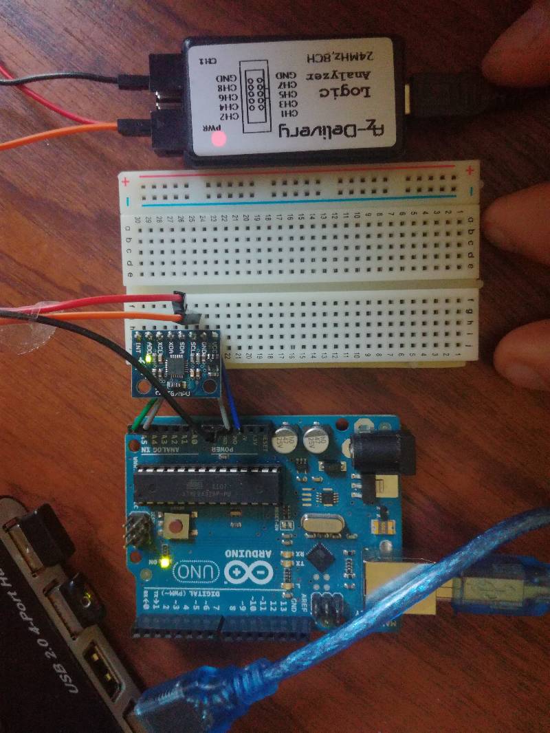
Gyroscope and Accelerometer GY 521
The second sensor we probed is an I2C sensor. This sensor is measures the orientation thanks to the gyroscopes and accelerations in different directions.
It communicates these data over I2C so it’s not a raw measurement.
It’s very easy and straight forward to connect 5V or 3.3V and GND for power and SDA and SCL for the I2C communication.
To get the measurement out, you first need to wake the sensor up by sending it a command over I2C and then it answers with the measurement.
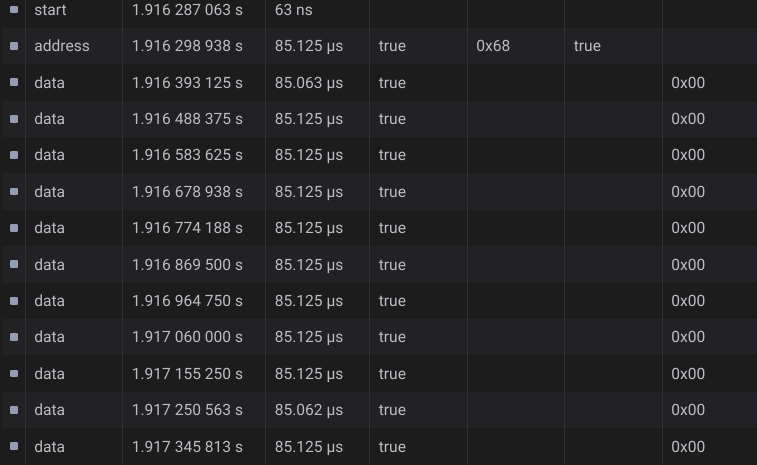
Once its woken up, it sends a stream of data over the I2C bus containing everything you asked for.