7. Introduction to the CNC
Before I dive into the extremely complicated design of my guitar, I spent an afternoon with Christophe so that I could get an understanding of how the CNC works and what I can/cannot do with it.
The CNC itself
The CNC is a computer-controlled machine that generally means is motorized and can move in multiple directions, according to the files that are fed into the program. In this particular case, when I refer to the CNC, I will refer to the CNC machine that we have at our Fablab: a HIGH-Z S-1000 that is controlled with the Kinetic-NC software.
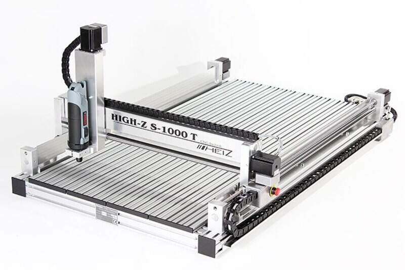
Using the correct milling bits, it is able to cut through wood, aluminum and some other materials in 2.5D (i.e. 2D with different heights and depths).
Equipment
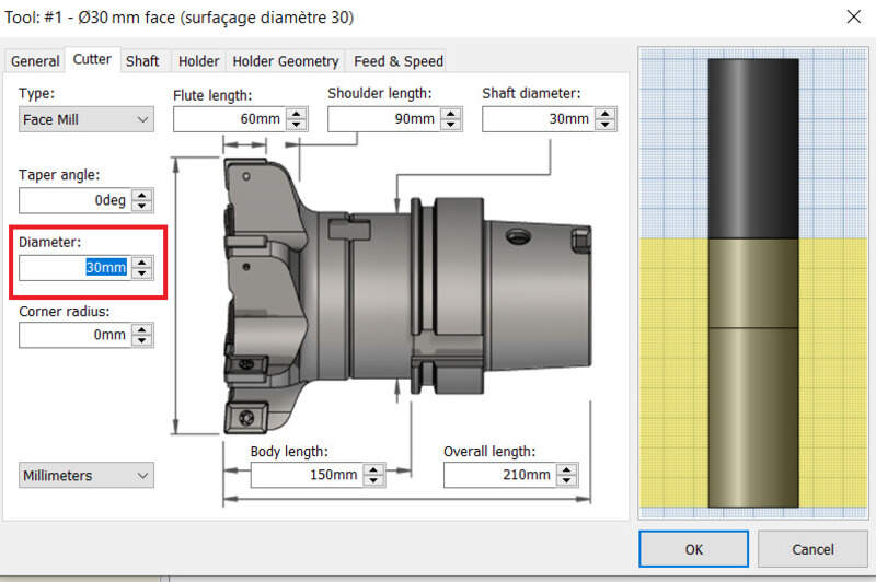
We lack a bit of mills at the Fablab so we were limited to using only 6mm and 3mm flat mills (201043 from Hoffman Group). Mills are usually defined by a few parameters: - The material they are made of - Their diameter - The number of flutes (i.e. the number of sharp edges at the bottom of the mill) - The surfacing speed (in m/min) - The feed per tooth (mm) - The cutting, shoulder and total length
Most of these parameters depend on the material we want to cut and not all mills are adapted to every material. It is therefore extremely important to use the reference catalog.
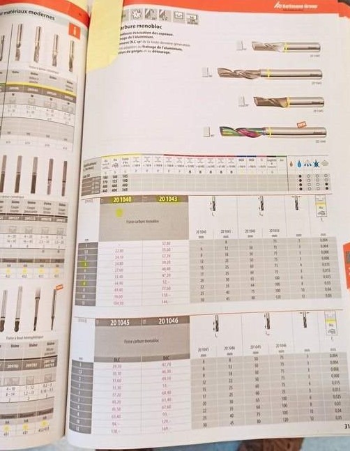
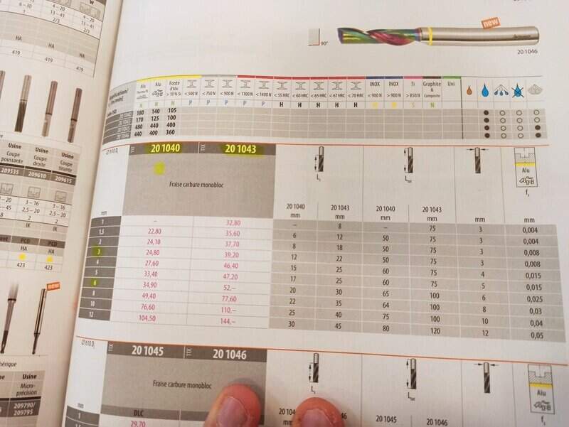
Note that wood is almost never indicated so we take the aluminum parameters. Some mills require coolant but we do not have any at the lab and when working on wood, it must not be used otherwise the wood will be soaked.
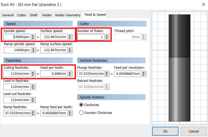
We can see that in the case of our 201043 mill with 3mm diameter, we can use a surfacing speed of 170m/min and 0,008mm of feed per tooth. The cutting length is 22mm and the total length 75mm.
The surfacing speed and the diameter will have an impact of the rotation speed (spindle speed), luckily, the CAM software computes this for us. However, our CNC has only present spindle speed settings (9000, 14000, 20000rpm mainly) so we must choose the closest one and adapt the surfacing speed to it.
The Kinetic-NC software is pretty easy to use and has two mains menus: jog and program. The first one allows to move the CNC around manually and zero the machine. The latter is used to load a CAM process and run. We can also slightly adjust the parameters once the program is running (0-150% spindle speed and feed per tooth).
Safety
A CNC machine can be a dangerous tool. The one at our lab cannot run whenever its doors are open and is automatically stopped whenever a door is opened. Moreover, one must always stay close to it when running in case something goes wrong. Cutting causes a lot of friction and heat and one must be extremely vigilant about it.
Also, it is always better to double-check your CAM process in the CAM software and in Kinetic-NC. An “air pass” is usually recommended at least for the first job on the part to make sure the stock is correctly placed and the zero is correctly set.
A CNC working can be quite loud so ear protections are recommend, especially if you spend your whole weekend in the lab  . Eye protection can be useful especially if the CNC is open, in which case a dust mask can also be proven useful.
Dust collection
Because CNCing something will create a lot of waste material, it is important to remove them in-between two jobs. I used a cyclone vacuum to remove most of the waste material but it ended up a bit blocked at the end… I then used a classical vacuum cleaner.
Making a CAM design
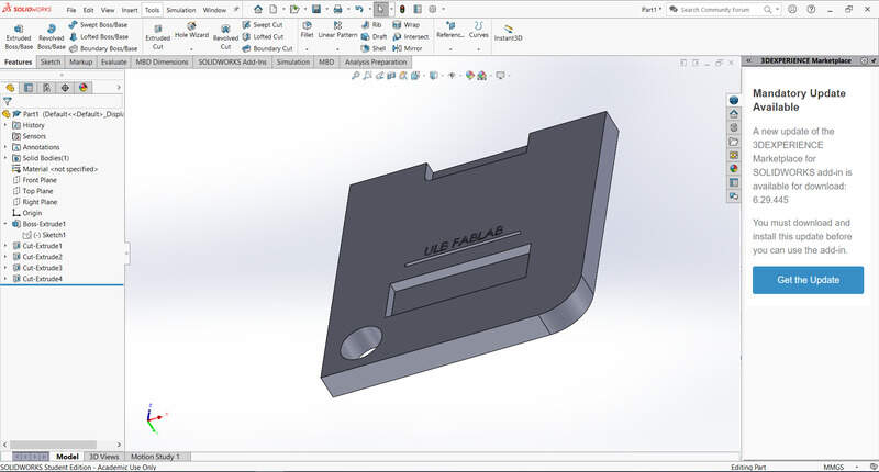
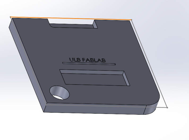
To test the CNC possibilities, I designed a small piece in SolidWorks that features sharp and round edges, engraving and enclosed and open holes (through all and blind).
That was the easy part. Now time to make the CAM job. Since I use SolidWorks, I had to install a CAM addon (newer SolidWorks version should have it installed but I didn’t for whatever reason). I went with the Autodesk HSMWorks software (free for edu students… How to access it after then ?).
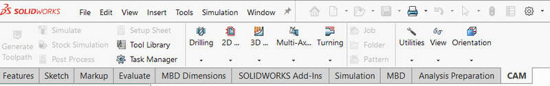
Once installed (and the computer rebooted), a CAM menu appeared on the top ribbon.
Setting up the job
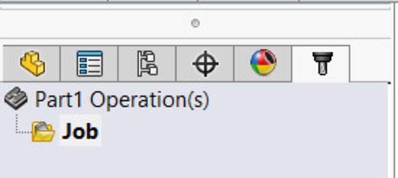
The first step is to create a new job.
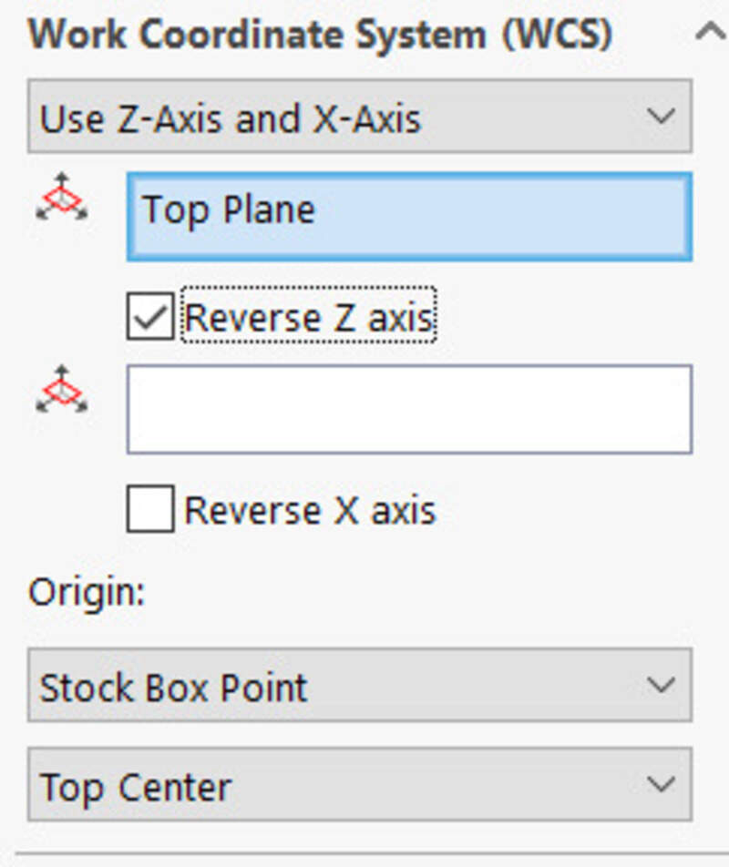
Inside the job settings, I need to set the coordinates system (selecting edges that will be my X and Y axis and a zero-position for the machine). On our CNC, the X axis is the longer one so I place the X axis along the longest edge.
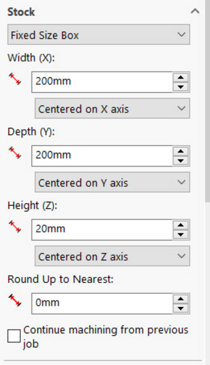
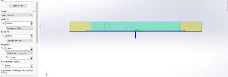
Then, I set the dimension of my stock, in this virtual test, I set my stock to be a fixed size box of 300x300x22mm.
I could then set my zero-position of the machine to be the either a selected point on my model or another point such as the top left corner of my stock.
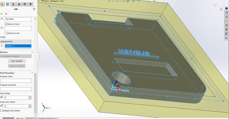
One need to be very careful about the orientation of the axis, in particular the Z one.
Surfacing the part
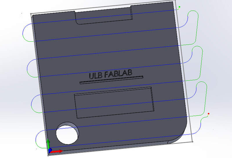
The first step is to surface the part. This will create an even surface for the part relative to the machine axis and will ensure that the finish surface is smooth and “new”. To avoid surfacing the whole surface of the CNC or the whole stock, I can create a new sketch that will be my surfacing boundaries (Later I found that I could actually surface the model contour, see below).
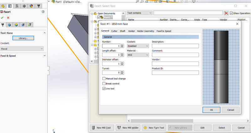
Tool library
I then had to choose the tool that I was going to use for this job. Usually, this step is done once for all projects and the mills are stored in a tool library but for this first time I had to do it now.
I could then set several settings for my surfacing: the contour to surface but also the height (top and bottom), the stepover between each pass and the maximum depth of a pass (usually set to maximum half the diameter of the mill, in this case I used 2.5mm for a 6mm mill). Here is the result of the surfacing job.
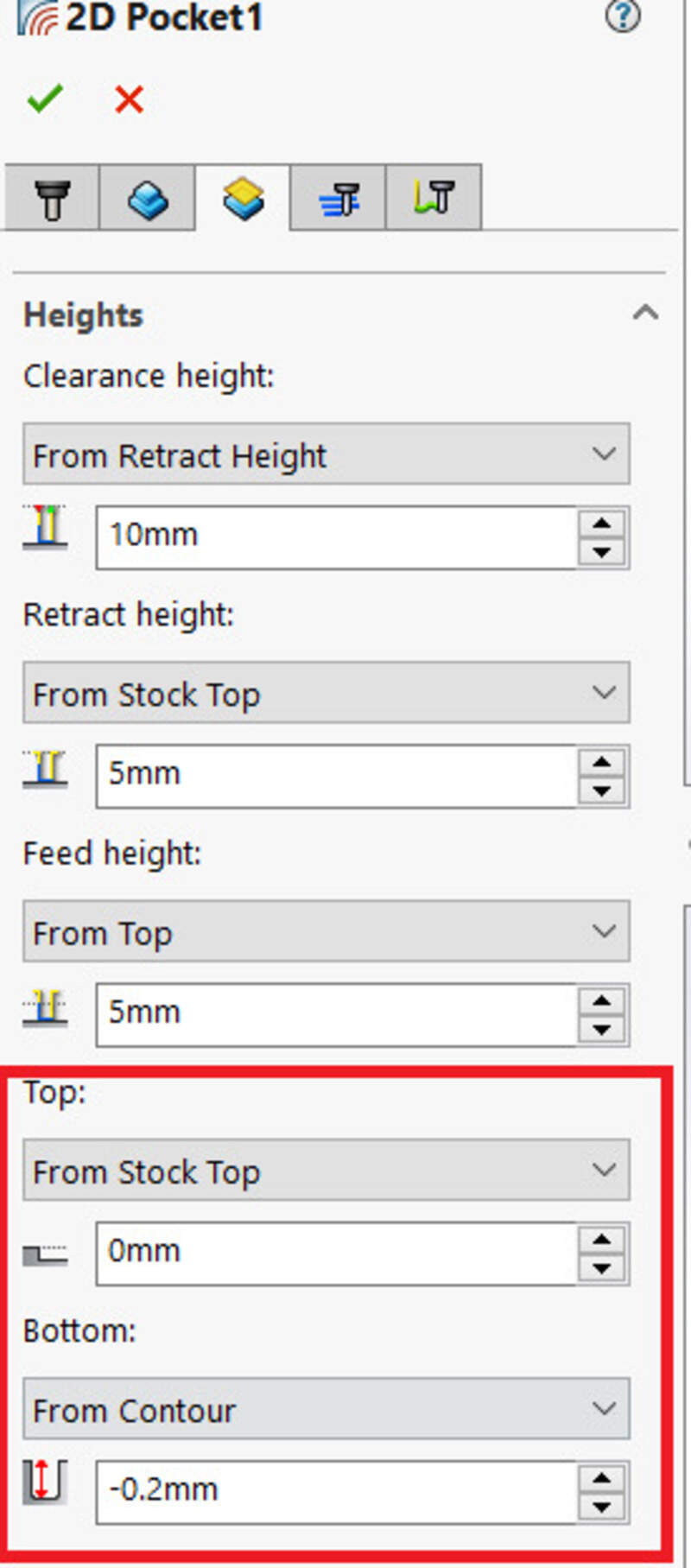
2D Pocket
A 2D pocket is a job that allows to cut inside the part to make a hole (a pocket). One must select the contour and either the bottom height or the contour surface to set the depth. It is extremely important to set the “multiple depths” settings to on to preserve the mill.
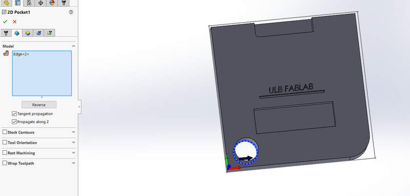
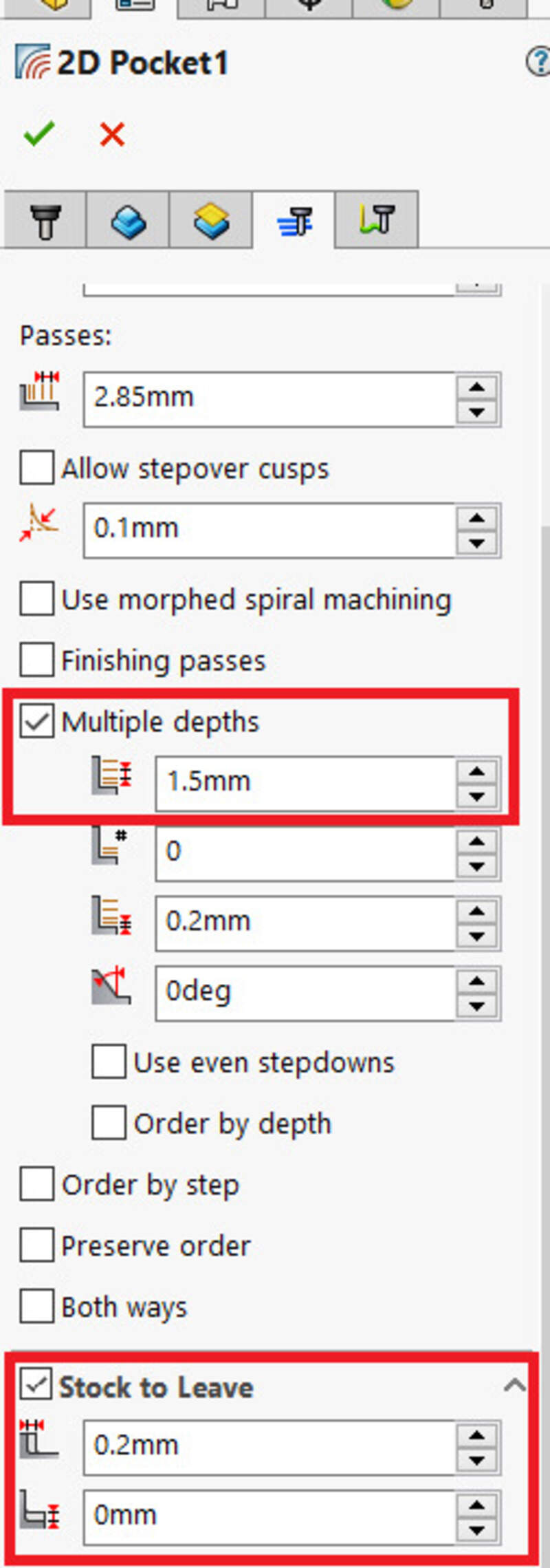
One can set a “stock to leave” if using a big mill to then finish the job with a softer touch and a smaller mill (using the 2D contour job). If only one pass (which I did for my guitar as I had not much time, then set it to off !).
2D Adaptive and other
Adaptive clearing means that the program will try to compute the path to reduce the load on the mill. However, this usually result in a longer toolpath but the material undergoes less force and pressure so the finish is usually better. There is no multiple depth settings there.
A lot of the options are also available. In particular, the 2D engraving too but also the 3D jobs that allow to make slopes with the parallel, 3D pocket, 3D adaptive, scallop jobs, … I used some of them to make my guitar.
Simulating
The final step before exporting the CAM is to simulate it. This allows to see the time it will take and help detect any issues. I highly recommend to do it.
Runnout
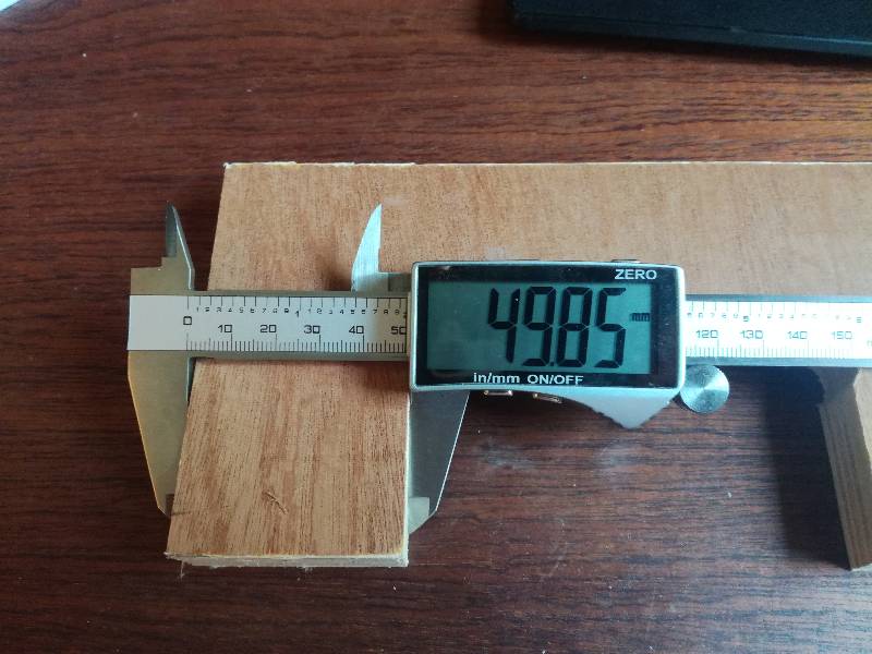
After that we calculated the runout of the machine.
The runout is the milling bit misalignment in regards to its axis making larger cuts than it should.
We made a piece with sides of length 50mm and an internal opening of 100mm.
Then we milled it and measured the deviation. In both cases, it was 0.12 mm which is the runout of our machine.