6. 3D Printing & Scanning
- Study Plan
- Research / Group Assignment
- Individual Assignment
Study Plan
Assignment definition
Group assignment
- test the design rules for your 3D printer(s)
Individual assignment
- design and 3D print an object (small, few cm3, limited by printer time) that could not be made subtractively
- 3D scan an object (and optionally print it)
| This week I wanted to | Result |
|---|---|
| Learn more about 3D printing by reading Stratasys education material | Ongoing, I did not have time to go through it all. |
| Learn how to 3D print my design | I learned how to use PrusaSlicer and tweak some features to get to a better result and adapt to the material and printer available |
| Discover the design constraints how our 3D printers | We printed a piece combining plenty of design constraints for PLA and PETG as well and a second one for clearance |
| Design and print a piece that could not be made subtractively | I designed and 3D printed a ball bearing |
| Build my 3D printer : an Ender 3 Pro and test it | Done, it’s working ! |
| 3D print the chandelier I had drawn in week 3 | I had to modify the dimensions to fit |
| 3D Scan an object using a commercial product | Failed, our 3D Sense is no longer working nor supported. |
| 3D Scan an object using opensource tools | Not succesful, but I am not far from the finish line: I acquired the images, searched for the camera specs and added these useful metadata with jExifToolGUI and then processed the images using Meshroom. I found a way to make it run without a GPU, as my laptop does not have one. Unfortunately, the resulting mesh is very flawed as I could check on Blender. |
Research
Stratasys: Manufacturing Constraints
3D printing if often presented as the go to solution but it is often limited in practice by practical problems.
Some of them are :
- Geometry changes: angles, distances, …
- Mechanical Properties
- Spatial resolution of the print
- Time
- Cost (of material/ printer)
- Materials available
But the freedom that it provides is also very impressive: * Geometry * Infill * Flexibility * …
The important thing is thus to know when to use 3D printing and when to use a different technique.
That’s why I’ll start by printing the different pieces that Neil showed during the course:
The other thing to know is that the flexibility regarding geometry and materials can cause issues and that bad parameters of the printer lead to many different type of failures

In the presentation of Stratasys, I found this nice 3D printed actionable flower and even if I don’t have flexible materials available, I wonder if I could do it using flexure mechanisms and an actuator.
I found this nice 3D packing software that looks like it could come handy so I’ll try it out. https://github.com/fogleman/pack3d
Technologies
Each technology has its advantages and disadvantages which can be taken advantage of.
Stereolithography : SLA
A light source (laser) cures a light curable material (photopolymers) and then moves on to the next slice by ascending the already cured part or lowering the printing stage.
Advantages:
- A wide range of material
- Very good accuracy, surface finishes and details
- Machines with large build volume enable large parts
Fused Deposition Modeling : FDM
A nozzle is heated to the melting temperature of the plastic used to 3D print. The plastic filament is then extruded through the nozzle and cooled down after exiting the nozzle to solidify it.
This is the most common 3D printer and is the one we have in our lab. Both the Ender 3 that I built and the Prusa of our FabLab are FDM printer.
Advantages:
- Very cheap
- Adaptable to most fusable component (Ideal for material with a low melting temperature)
3D Printing
We documented the calibration in detail our group assignment here.
Introduction to 3D printing
We were given a short presentation of how PrusaSlicer works and how it is compatible with other 3D printers such as Ender 3 which is the one we’ll build.
The printers we have at the labs are Prusa MK3 and Prusa MK3S
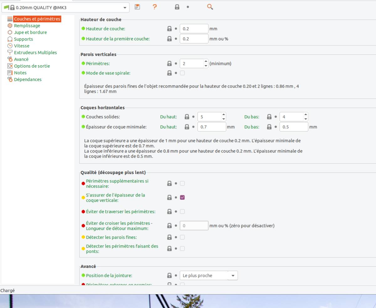
For time and material reasons, we were advised to look around 10-15% and always to stay below 35% infill and play instead with infill patterns. Plenty of options can be set up in PrusaSlicer and I’ll continue to discover them over the next weeks, the most important features are : * Material selected and specifically the temperature of the nozzle required. * Adding a border to facilitate the adherence of the piece to the board * Supports to avoid deformation of the piece that can be automatically added everywhere or only on the bed
The presentation can be found here
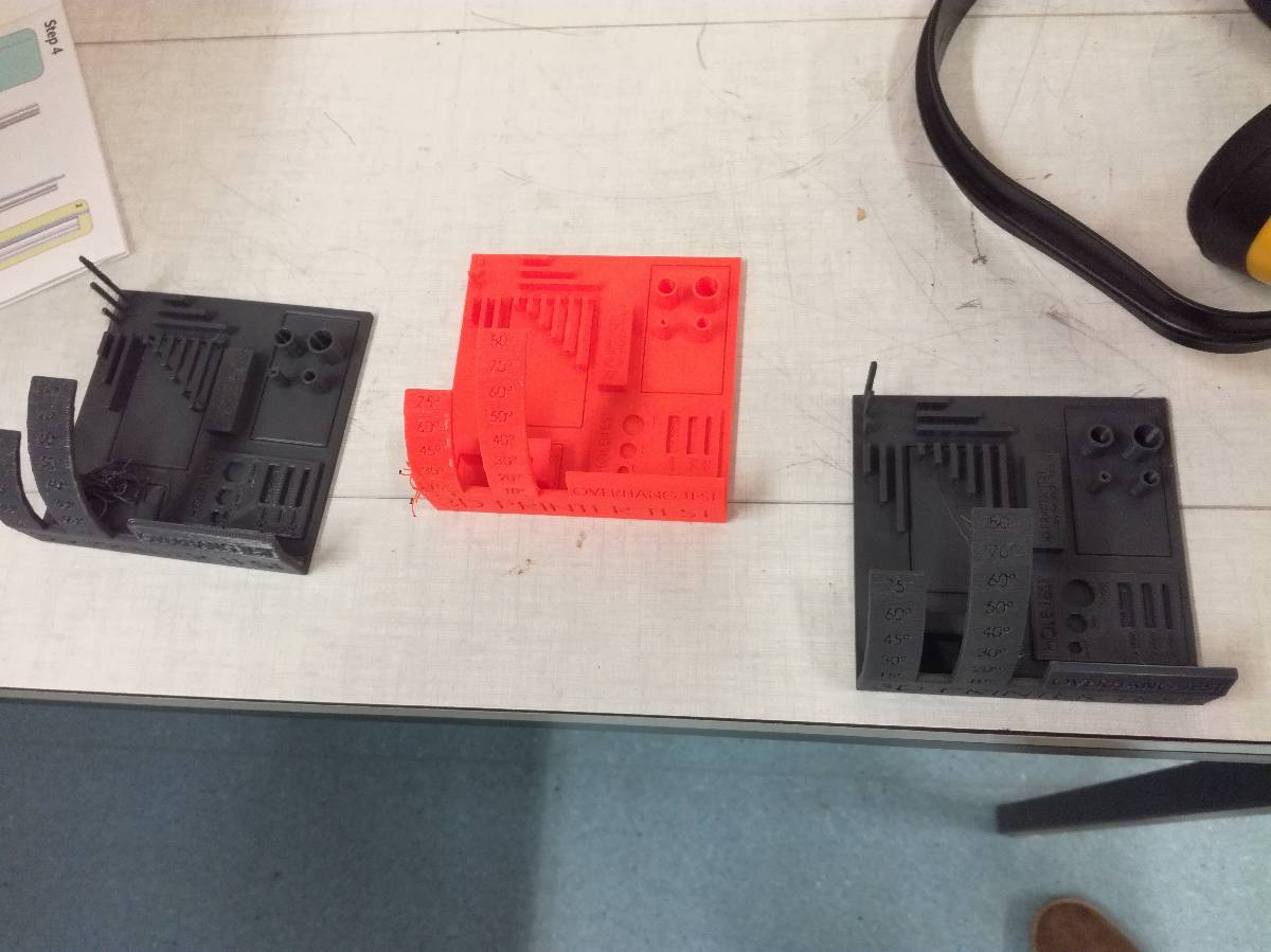
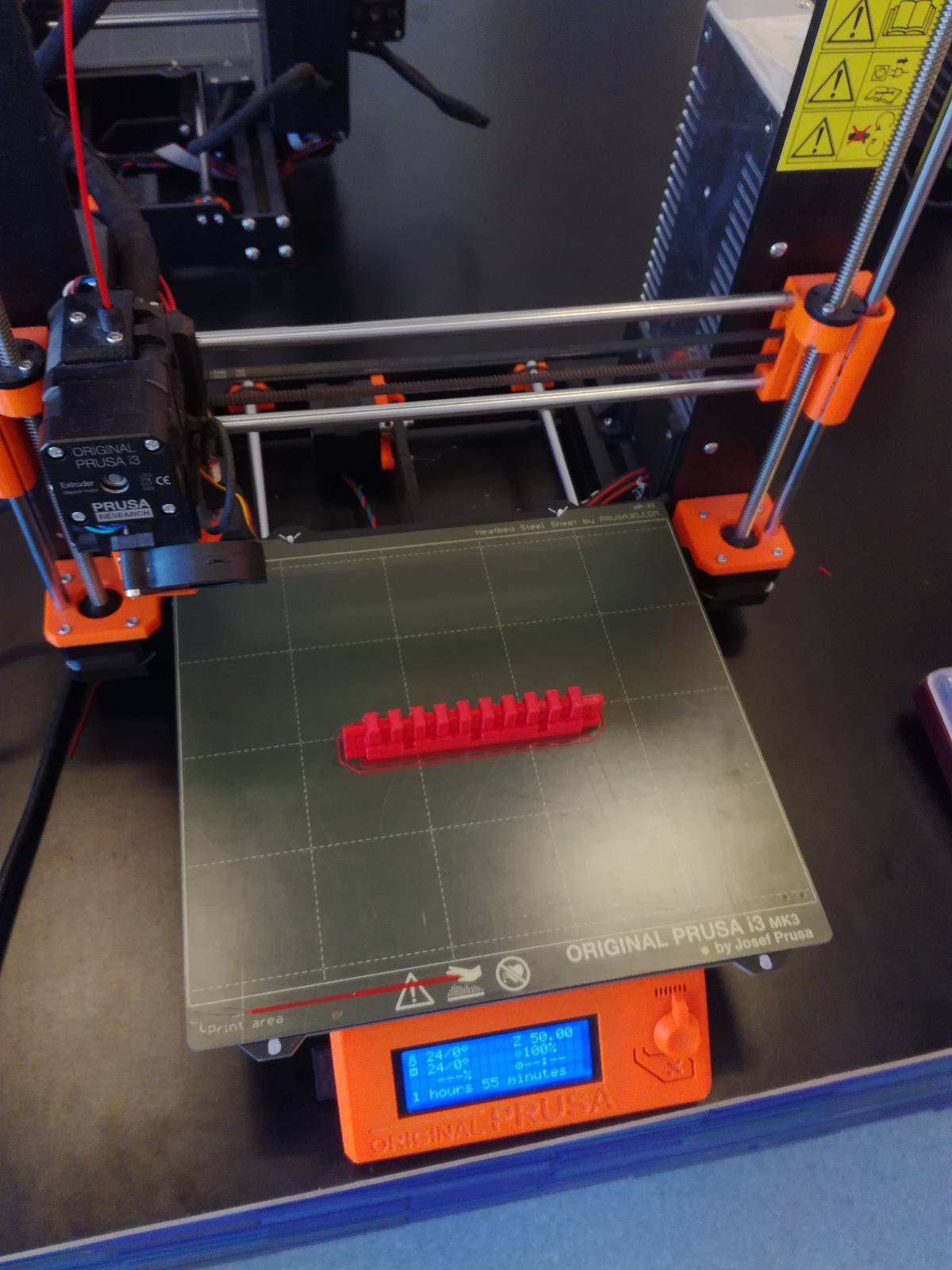
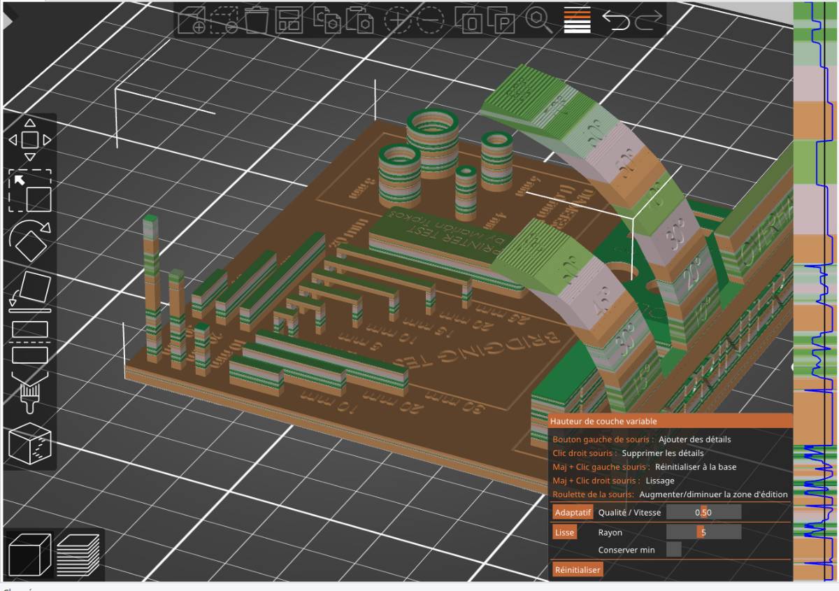
Then we printed different pieces to check the design rules of our printer.
Calibration and design rules
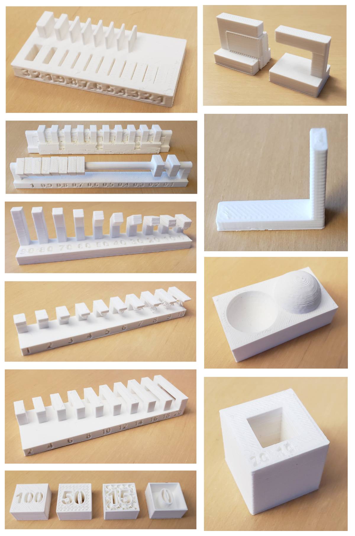
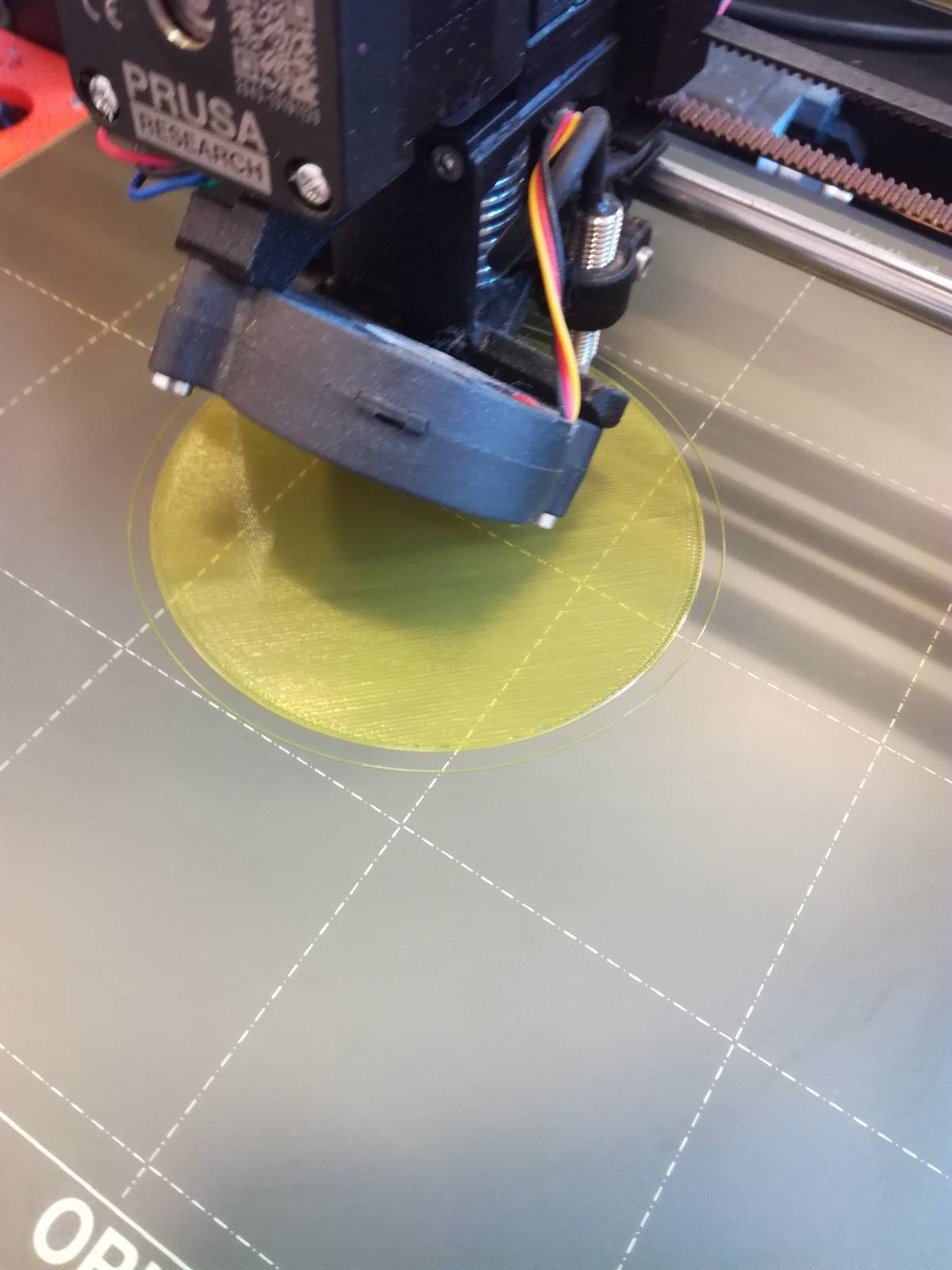
We started by printing a design rules file that we found online, containing most design constraints in one piece. This will be very practical as we’ll be able to keep it at home and check it to verify what is acceptable or not for our 3D printer.
The clearance test was missing in that piece so we printed the one provided by Neil.
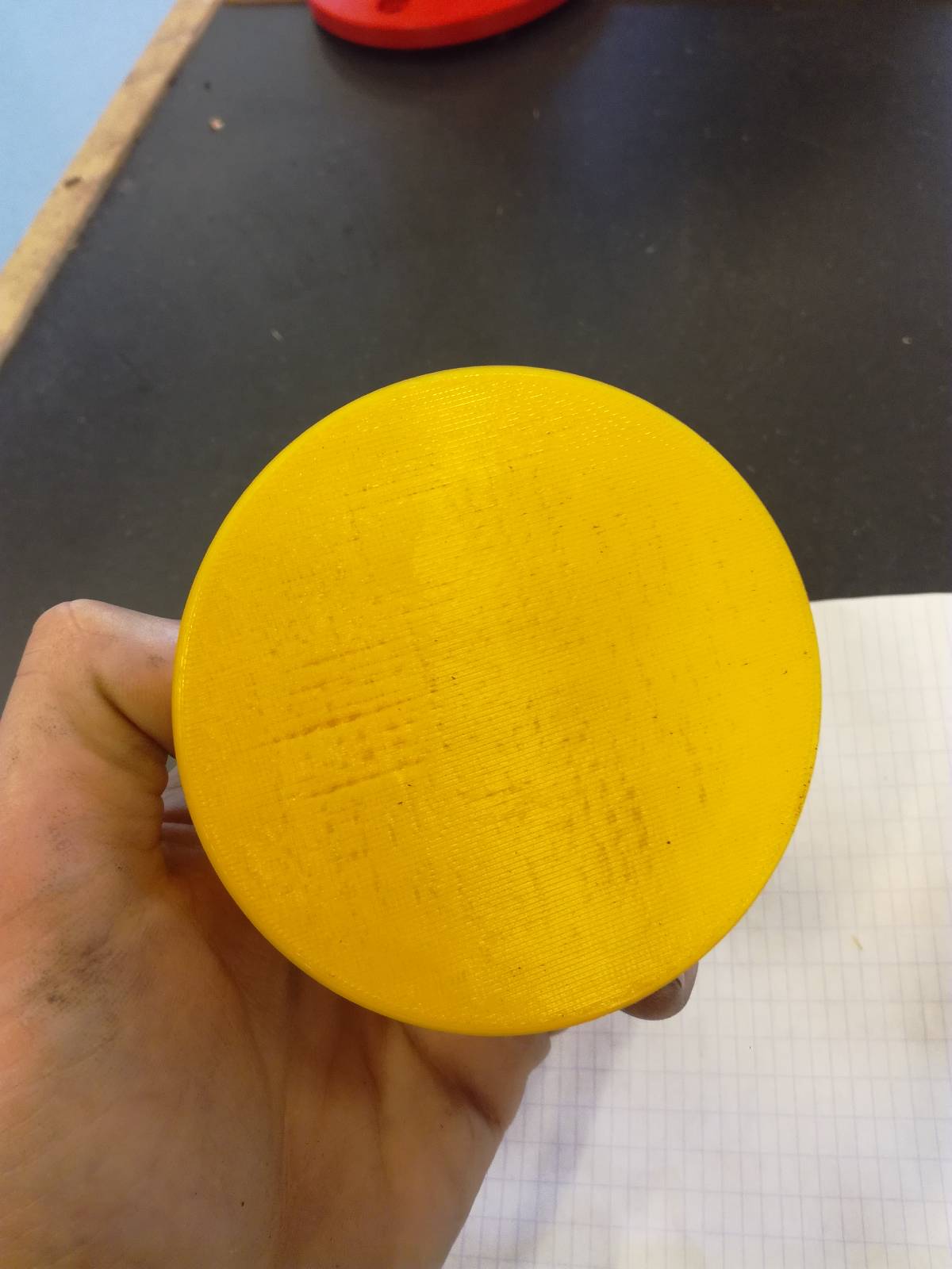
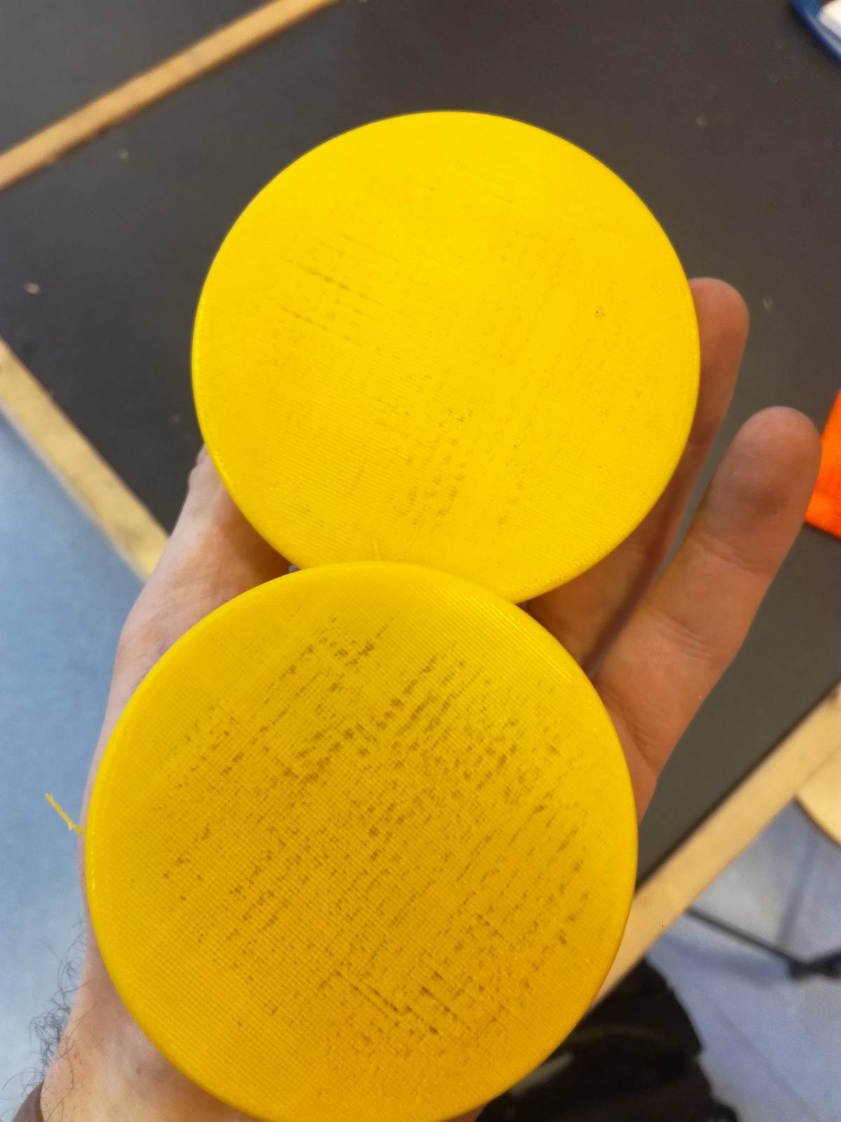
The PETG burned a little for some unclear reason.
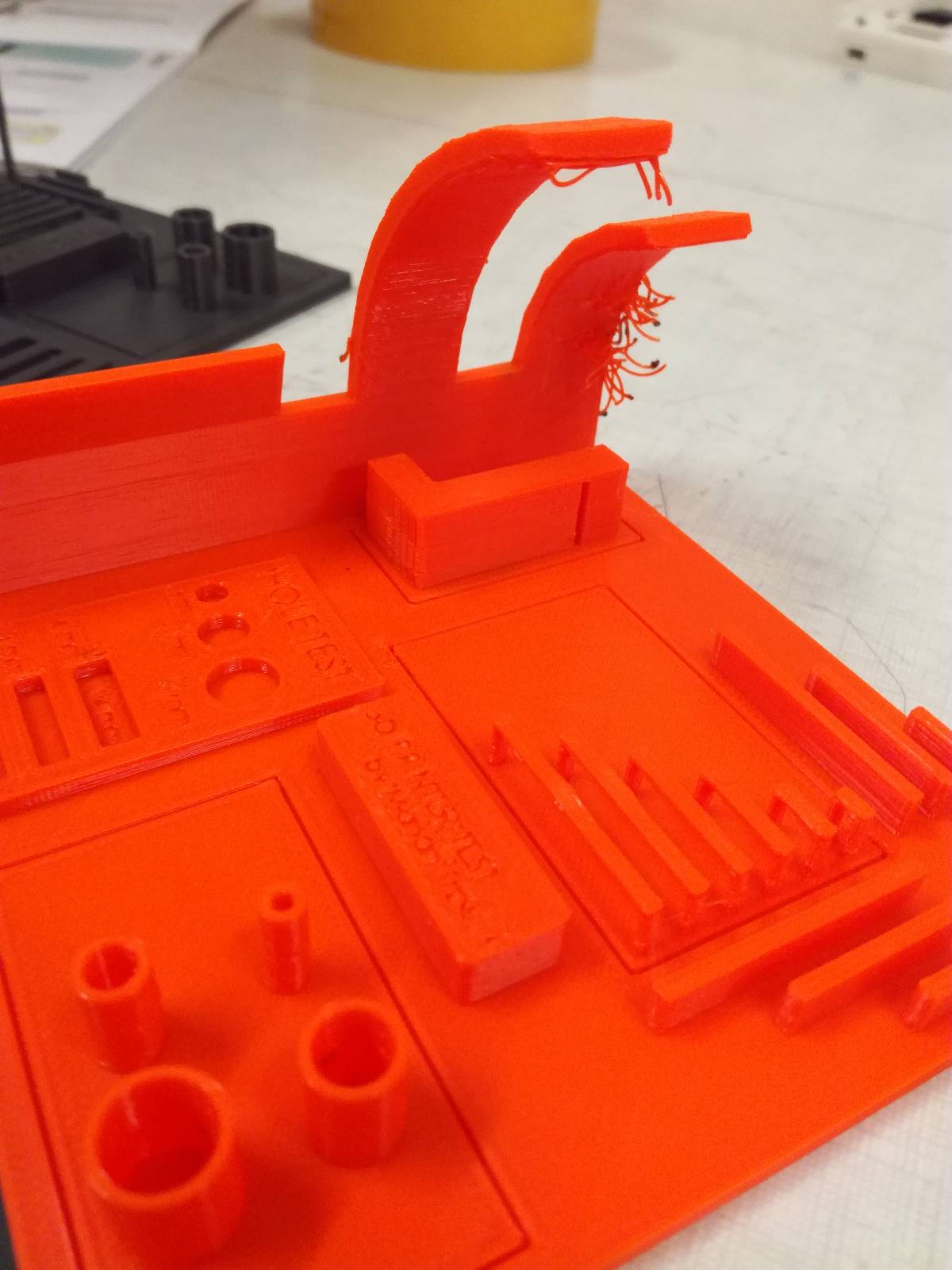
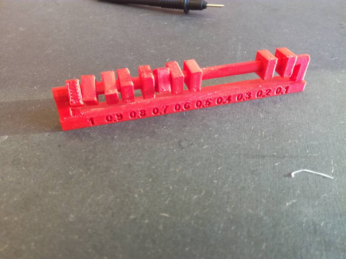
The PLA 0.6mm showed some defects when the filling was too limited
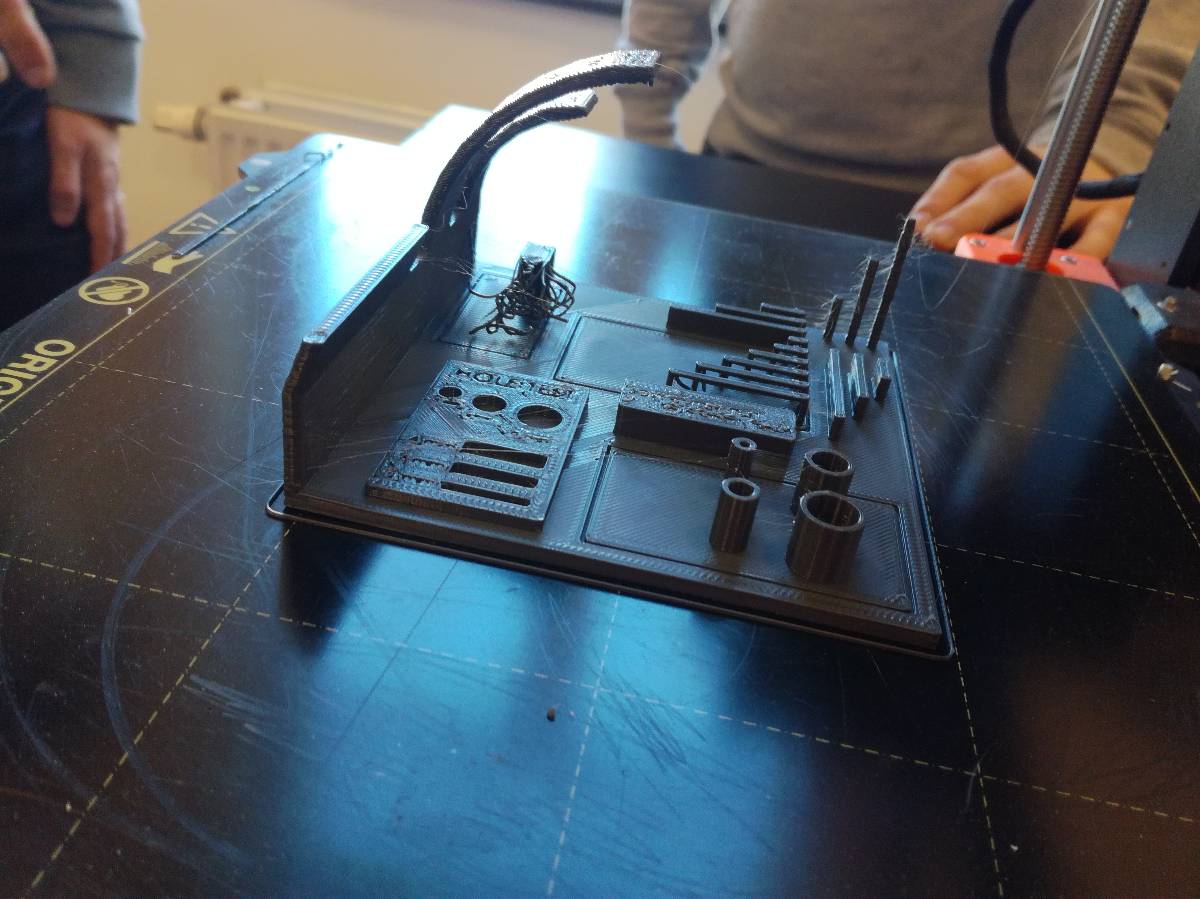
The clearance test piece was printed using support.
We found out that clearance of 0.3 mm was sufficient to detach easily the pieces and later, I forced the 0.2 mm and if worked as well but barely so we’ll stick to 0.3 mm. Later, I pushed harder and managed to get the two others moving but not easily and I damaged them a little.
We also discovered that it was possible to do the trade off between speed and quality of printing dynamically, depending on the level of details required. It can be done automatically in PrusaSlicer 2.3 but in PrusaSlicer 2.1 you have to do it by hand.
Designing a 3D object
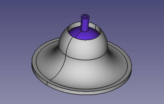
I wanted to design some sort of flexure based flower that would open if you turned the base, similar to the one I found in Stratysis presentation but using fairly rigid material (PLA). I thought about it and it’s much too complicate, at least in such as short time, so I decided to design a custom made ball bearing that I could later use in different projects.
Slicing it
To slice the image, we used PrusaSlicer and it’s actually incredibly easy and user friendly so great job for that Prusa !
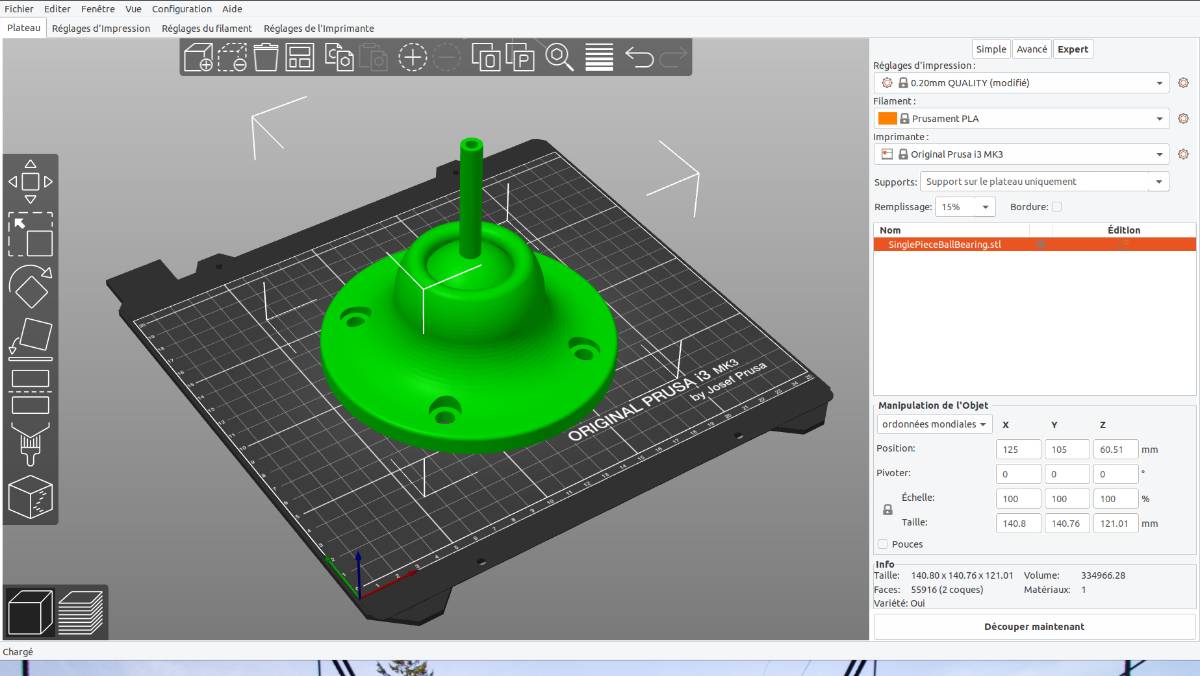
Then off course, there are really a lot of parameters you can tweak to get to the optimal result for your print, but there are different tabs from simple to expert to avoid confusing the user so it stays very comfortable.
Once you are done with the set up, you simply click “Slice now” then check the result illustrated below.
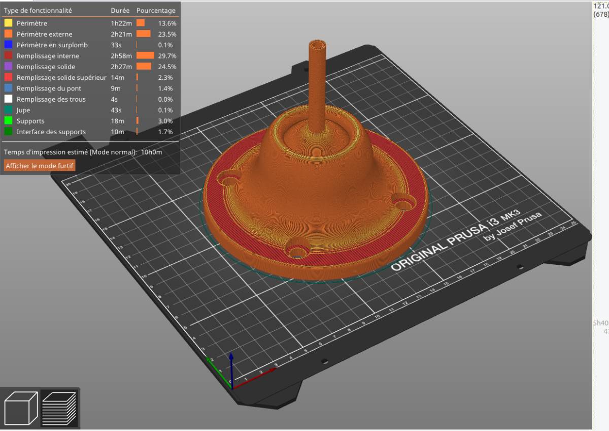
And if you are satisfied, you load it on a SD card on stick it in the printer to print it.
Printing a 3D object
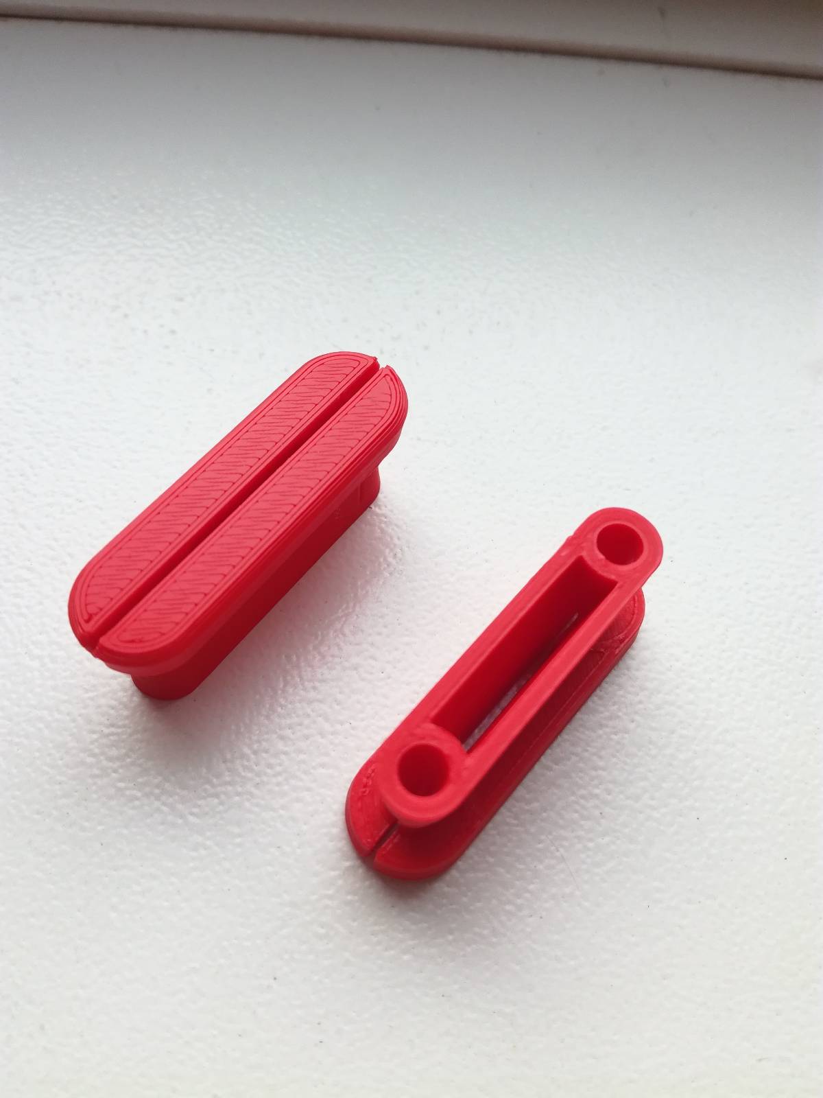
The first objects I printed were a direct success : the some enclosed sphere joystick and a curtains blocker.
This joystick like enclosed sphere is not manufacturable using substractive methods because the sphere inside could not be separated from the exterior.
Later I also printed the OpenFlexure microscope base which is clearly impossible to make by other means than 3D printing with all its internal cavities !
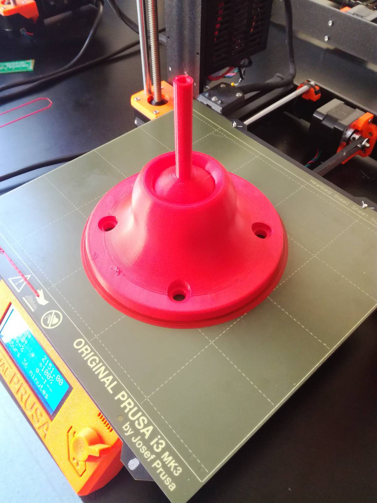
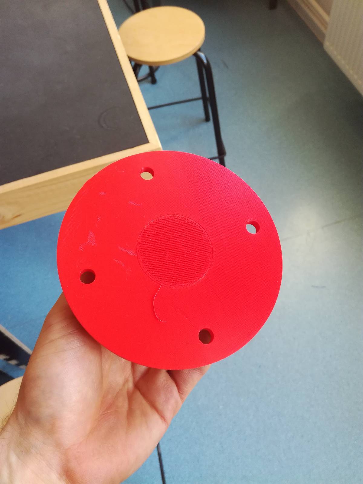
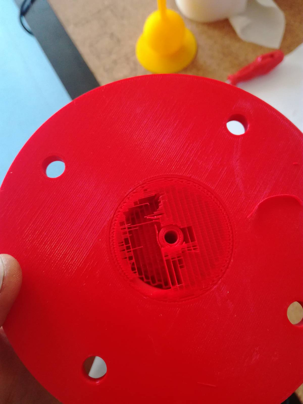
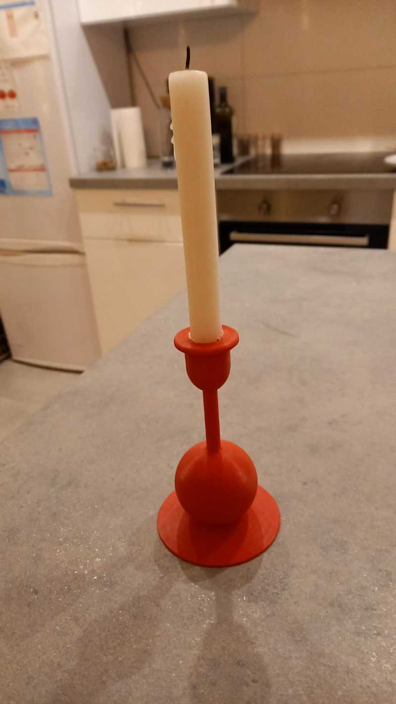
Then, I decided to 3D print the chandelier I had designed for my girlfriend in week 3 and that did not go so well.
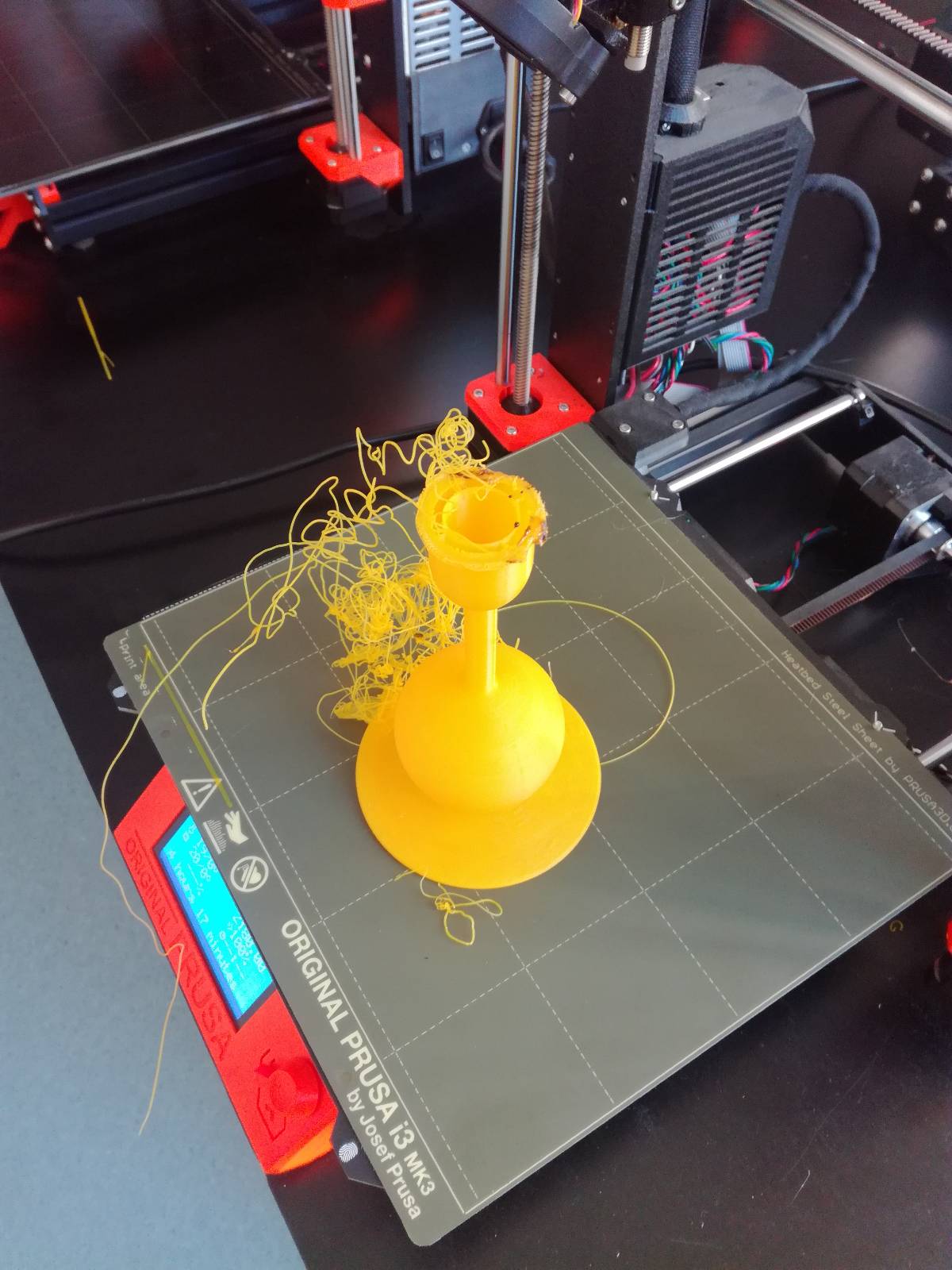
The first try really failed. It was not clear why as there could be different reason.
I started my case study.
The first hypothesis was that the neck was too long without support and deflected making the head of the chandelier move in regards to the printing head so misaligning everything and causing havoc.
Asking the fabmanager, in her experience, that was unlikely, so we looked at the bottom of the piece. The bottom was skewed and had most likely been detached before the end of the print. It was problematic so I cleaned the bed with acetone to make the PLA stick better and printed again.
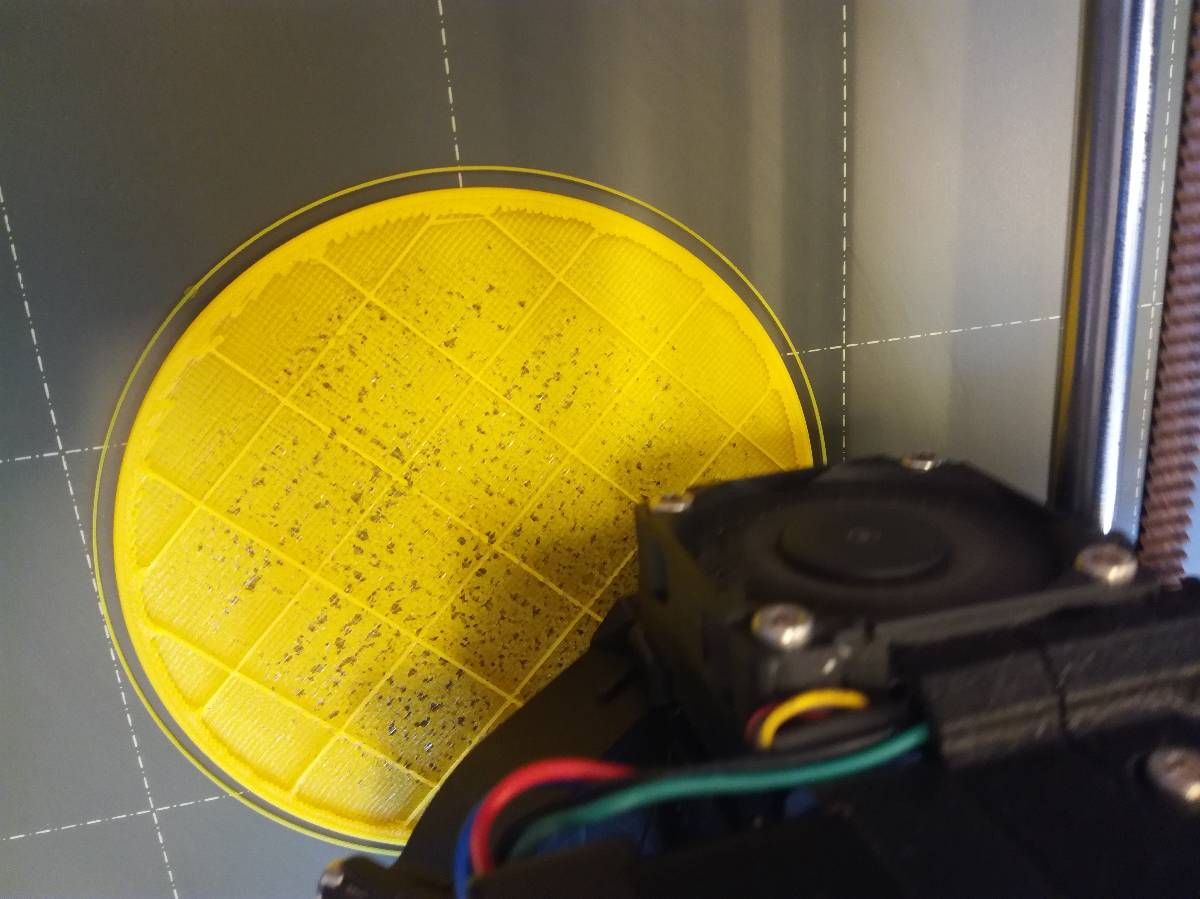
That was a problem but not sufficient to solve the problem checking during the printing of the first layers, I realized that they were not homogenous and I suspected that was the problem.
We interrupted that print and started anew.
This time we increased the nozzle temperature from 215°C to 230°C. and increased the printing speed on the first layer to increase the chance of adherence and it looked nice. However, at the second layer, it looked bad again, so I interrupted the printer and tested on another one, and it went great.
I did have some problems at the neck because the neck angle was too steep but it was totally manageable, my girlfriend is happy.
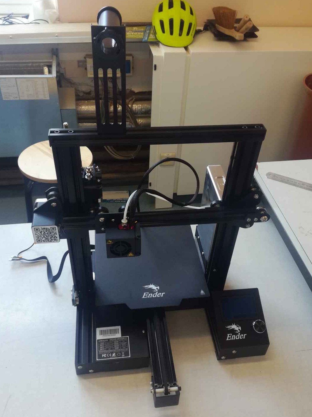
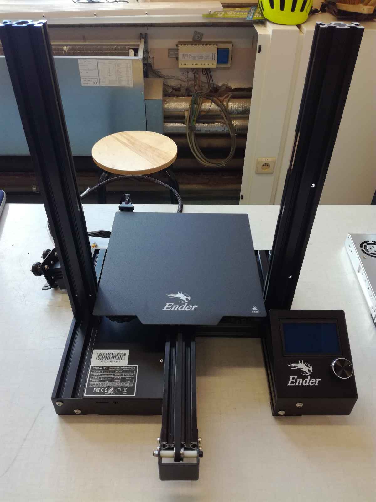
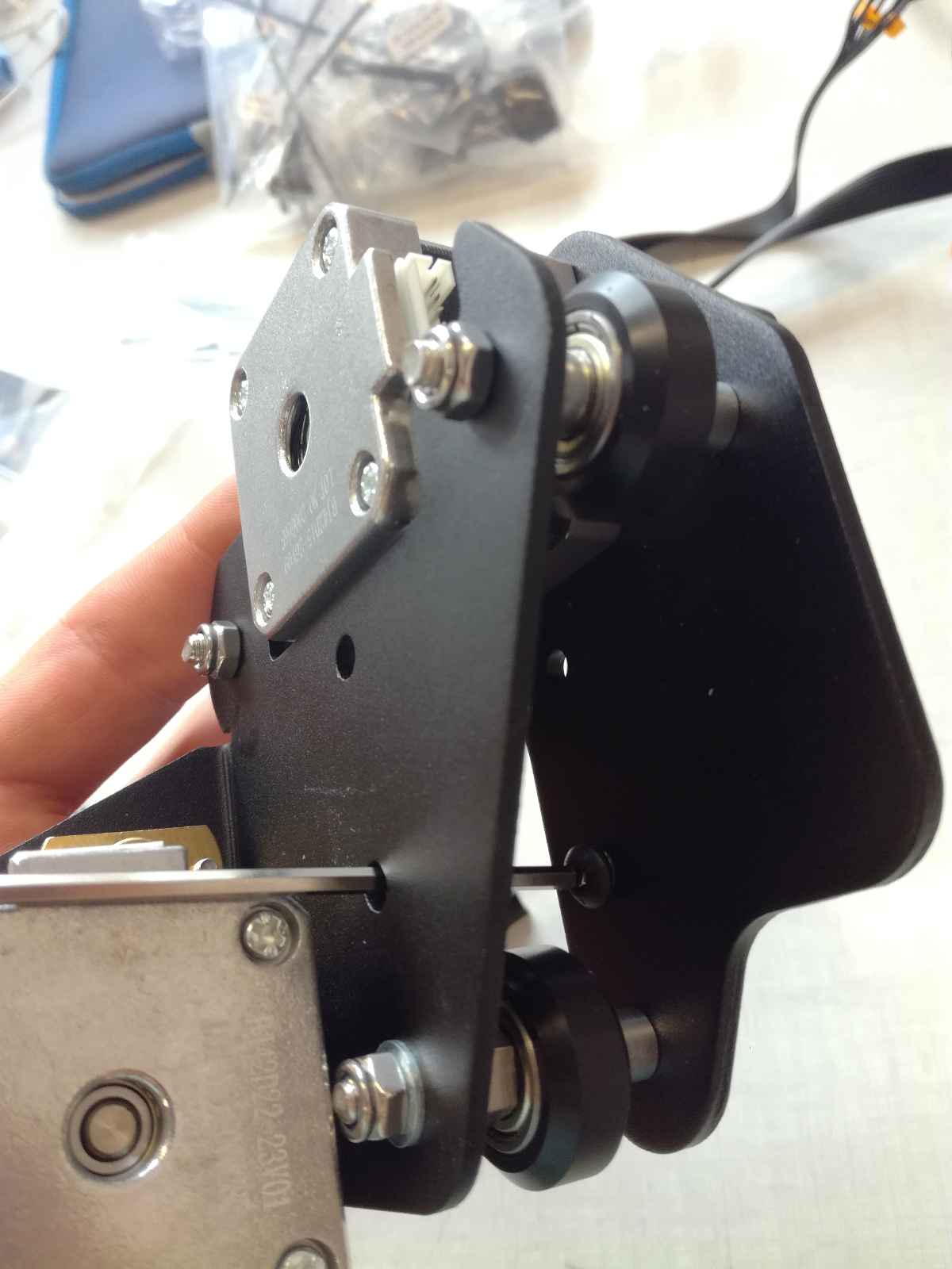
Building the 3D Printer : Ender 3 Pro
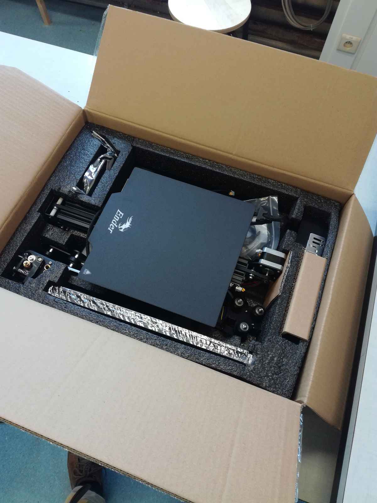
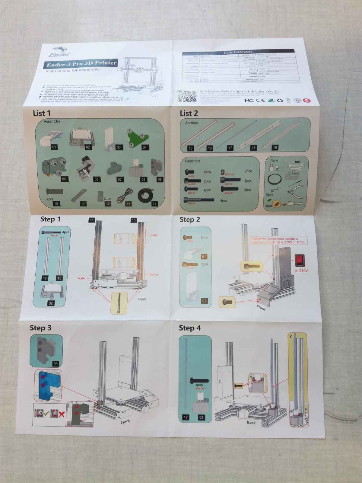
In case of a new lockdown, we decided to assemble our Ender 3 Pro to have a way to 3D print from home.
Assembly
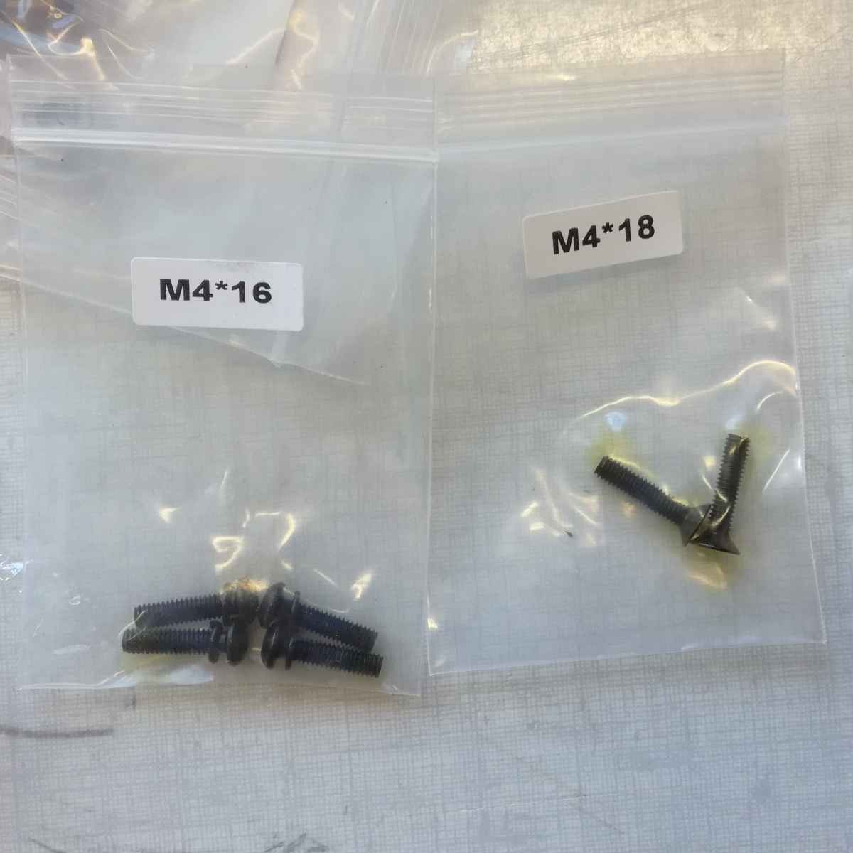
The printer was very well packed and the instructions quite clear. I just had an issue with one step which took me a long time too figure out, the filament “connector” to the extruder.
 |
 |
|---|---|
| The printer is well packaged | The instructions are clear |
Once you open the box, you just have to screw a couple of piece together in a very intuitive way and it works.
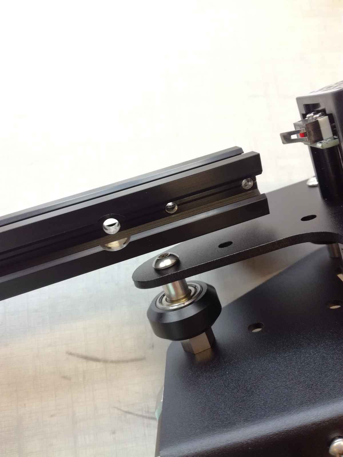
Another nice touch that I should pay attention to in my own designs are the holes for the building tools.
In a couple of hours, I had built my own 3D printer and I was ready to print, or so I thought.
Loading Filament
The first thing to do once the printer was assembled was to load the filament but that was more challenging than it looks as I was now accustomed to the extruder on the printing head as it is the case on the Prusa printers.
Therefore, I directly inserted the filament there but it would not pull…
I later realized that actually the step I had missed building the printer was specifically to connect the filament tube (holder) to the extruder motor.
I thought I had done it right and checked a tutorial but still did not understand where I had it wrong even though the tutorial clearly explains that you have clamp the wire but I did not get it at first …
Once I understood that I had to connect the tube to the extruder, it was much easier.
Bed Leveling
I found another tutorial to help me:
I started by using a thin piece of cardboard then I used a piece of paper.
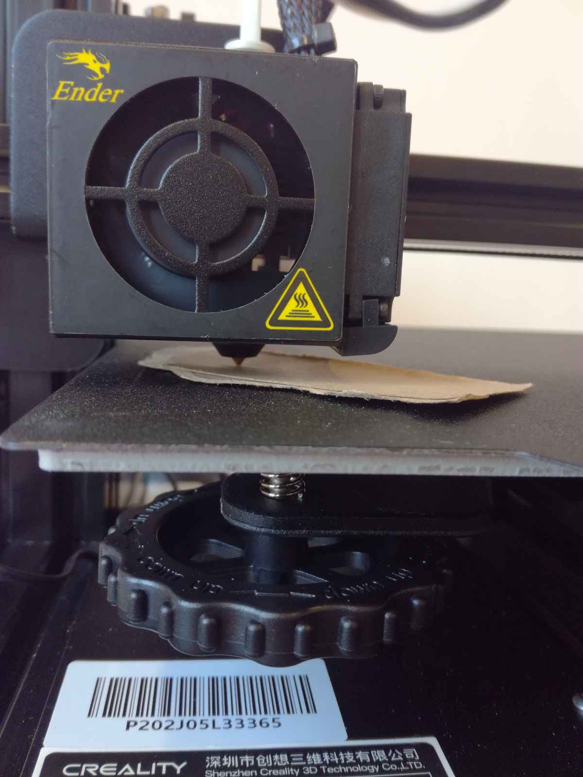
Because the bed was very far off so I had to unscrew all corners at first to get a very rough alignment by eye and then correcting precisely afterwards.
Unfortunately, I had not a good control of the machine so I poked holes in the magnetic bed two times.
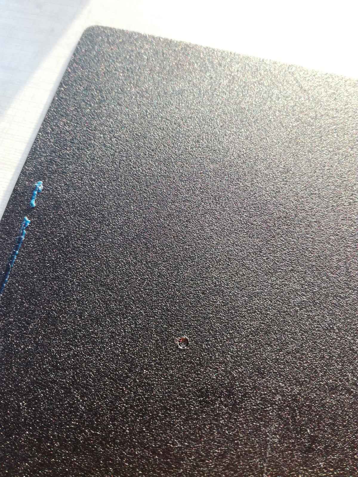
And finally, because some PLA was not coming off my board I tried to clean it with acetone and it was a bad idea as the bed was in plastic and acetone melts plastic …
But making a similar mistake a second time, I should not assume that all printers are the same.
3D Scanning
For the 3D scanning, I wanted to try the scanner we had but decided to go with photogrametry as it is a “simple” technique, meaning that is does not require a lot of expensive hardware to use and there are available software for the processing.
Commercial Scanner
We have a 3D Sense at the lab but unfortunately, it does not work as the software is closed source and no longer supported by the manufacturer.
This is an excellent example of closed source systems failing the end user !
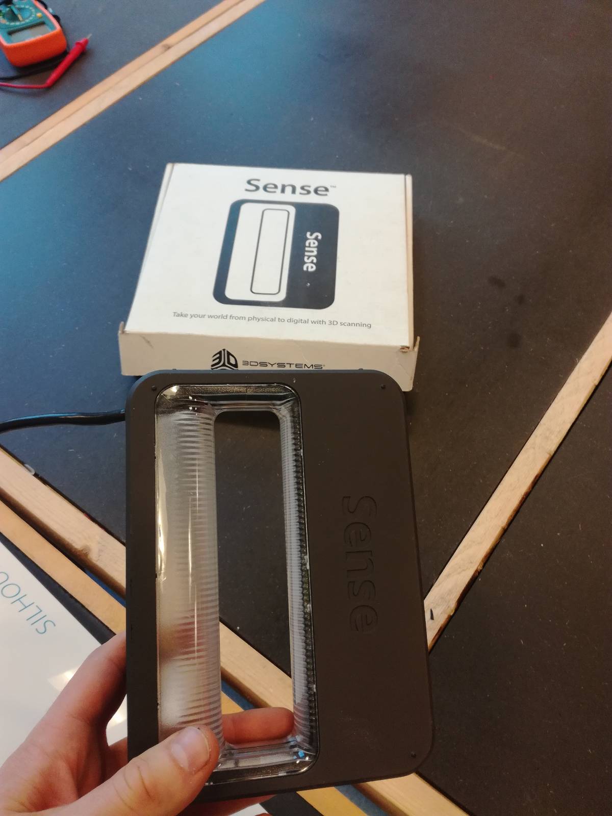
Later notes : Following some people in the FabAcademy network, it is possible to find a version of the software. However since it worked without it and that I do not have a 3D Sense at home, I haven’t investigated.
Opensource solution
I then used available on hand solutions:
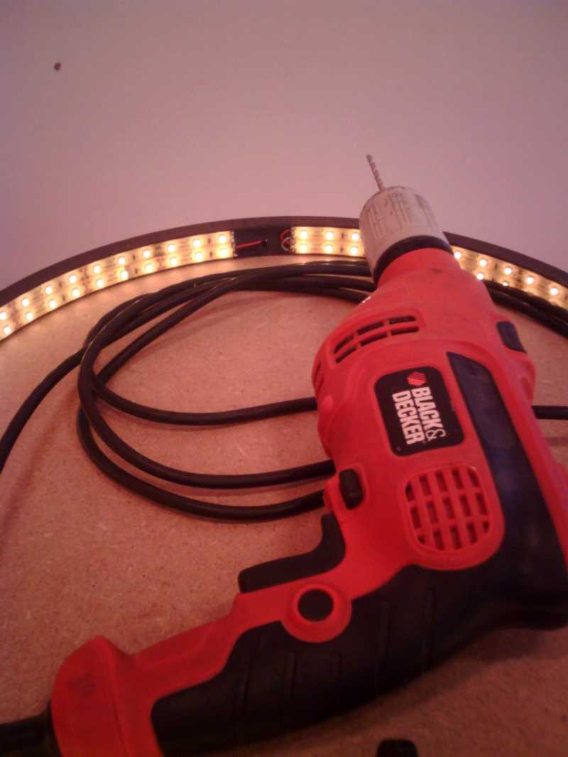
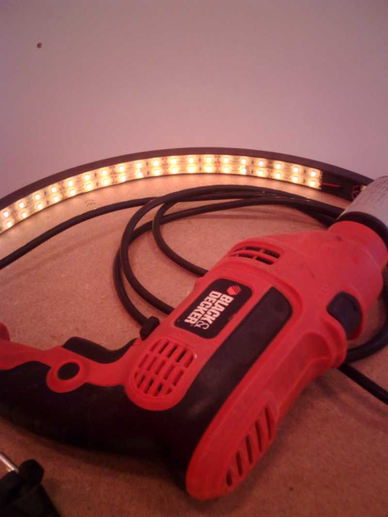
- Hardware : The 3D Scanner of Quentin Bolsée who built it last year during the fabacademy.
- Software : I used Meshroom from AliceVision to process the images acquired.
Scanning the object
The advantage of Quentin’s scanner is that it takes the images automatically and in a homogene and repetitive way.
To connect to the scanner you have to connect the same wifi network and then go to the appropriate address (defined in the scanner code.)
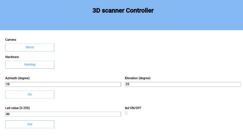
There you can control the scanner manually.
Off course, the objective is to control it automatically and let it run on its own so I used a little python script Quentin gave me. The script is contains a for loop calling continuous request to make the scanner move and then retrieve images automatically through Wifi.
Reconstruction with Meshroom (1st try)
I first tried to start the image processing with Meshroom while working but it is very intensive on the processor so I waited to let it run when I had some free time.
I let it run for some time but then it crashed…
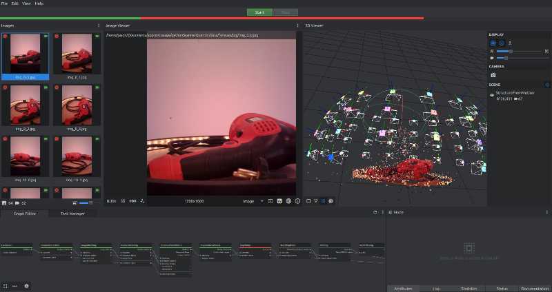
I checked the log to find why and realised Meshroom required to have a GPU, which I don’t have.

Asking for ideas, Quentin indicated to try a solution to use Meshroom without GPU, that I linked hereunder.
In a word, you need to delete the steps in the pipeline that require the GPU and connect the remaining elements.
The GPU is required to calculate the depth field and as you will see it’s quite important.
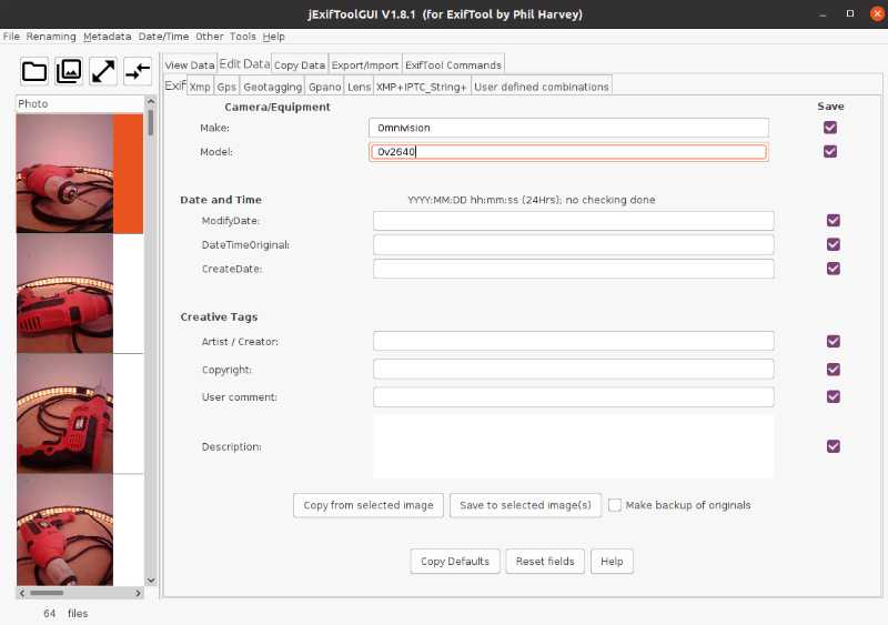
Adding EXIF Metadata
Quentin seeing my screenshots also advised me to add EXIF metadata to the images to facilitate the computations by providing a good initial value. Because I was removing the GPU who does the heavy lifting of the computation, I tried to alleviate some of the pain for my weak CPU.
The useful information for Meshroom is the lens focal length and the image width. So I had to add that to the metadata and make Meshroom able to get this information.
I had no idea how to do that.
So I started looking online.
First I had to add the camera to the database of Meshroom.
I started by searching for the data to include : The camera mounted on the scanner is an ESP32 using the camera module OV2640. Looking in the datasheet, I found its focal length (35mm equivalent on a 35mm full frame) and the width of the sensor (2.640mm hence the name of the sensor I guess). To add the Camera to Meshroom database, I followed the wiki of Meshroom and added the following line to the file.
Omnivision;Ov2640;2.640;source
The formating of the name was not really relevant in my case because I anyway had to change the metadate manually so the important thing was that the name in the metadata was the same as in Meshroom database so that it can connect these two informations.
The I started to look for a way to edit the metadata.
I found numerous ways to do it:
- exiftools : a command line package for photographers but the documentation was not clear enough for me and thus, after failing to understand how to use it I searched a tool easier to use.
- digiKam : a GUI tool for photographers that can do a lot of things including editing the EXIF metadata. Unfortunately, you cannot process multiple images at once and given that I had 64 images to modify, I searched for something else.
- jExifToolGUI : This is a GUI for exiftools. This is good news because everyone online says that exiftools is great but I had not understand it. With this is a couple of minutes I was done !
To install it, just go to https://github.com/hvdwolf/jExifToolGUI/releases

Running it was easy and very intuitive. You load your images, select the ones you want to edit the metadata of and then save the changes to selected images.
Reconstruction with Meshroom without GPU
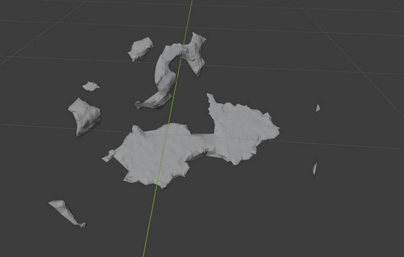
Once I that was done I started the process again, it completed but it was not satisfying…
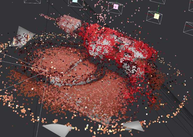
When imported in Blender, it gives this result :
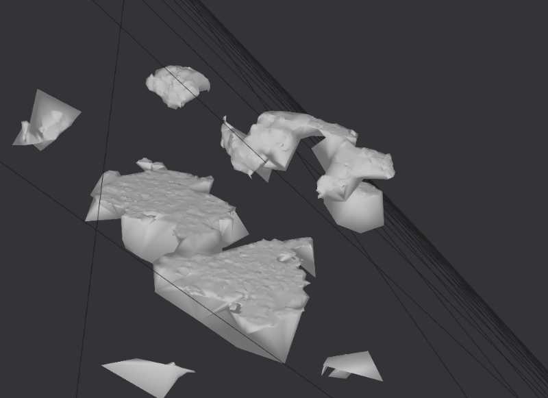
Reconstruction with Meshroom with GPU
The steps we had deleted to work without GPU were critical for this reconstruction, so I sent the data to Quentin to process them on his GPU with Meshroom and a couple minutes later, he sent me back the result.
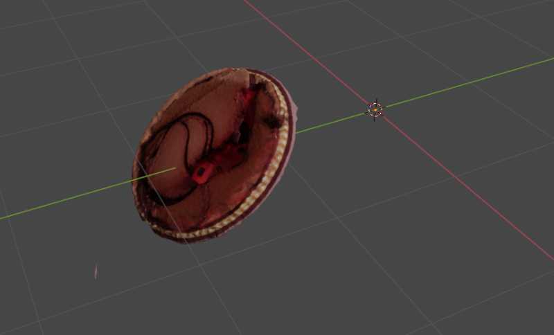
The orientation from Meshroom is a bit skewed and there are some artifacts, so I fixed that in Blender and after a couple minutes, here was the result :
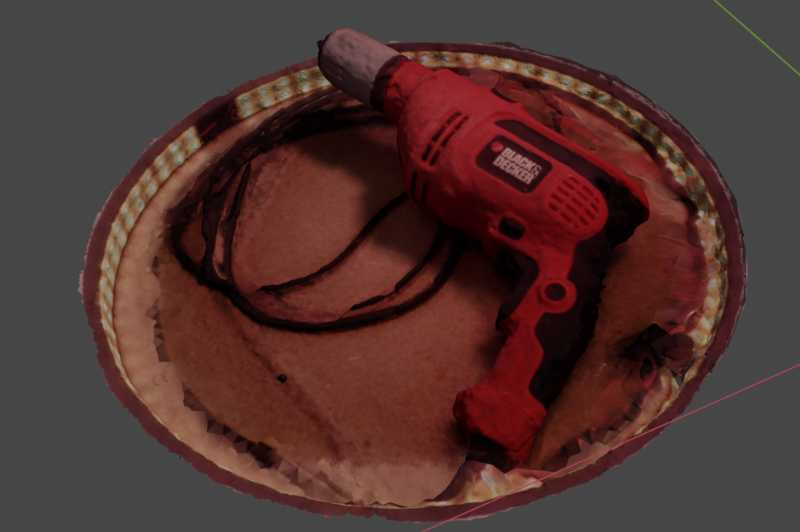
What I find particularily interesting is the texture mapping because then it is much easier to imagine the real object.
Files
3D Printing
The calibration files come from thingyverse for the general one:
https://www.thingiverse.com/thing:2656594/files
and from the fabacademy website for the clearance:
Because of their size (multiple Mb), I did not host all my STL files on my repository, however recreating the files is very easy with FreeCAD for the chandelier and the ball bearing.
If you want to directly print it, here is the file but I advise you to recreate it using PrusaSlicer.
Using FreeCAD, you need to: 1. Select the body you want to print out, export it in STL 2. Open PrusaSlicer 3. Import the stl file 4. Set up the parameters of your printer 5. Slice the design and you are good to go !
3D Scanning
Python script to control Quentin’s Scanner
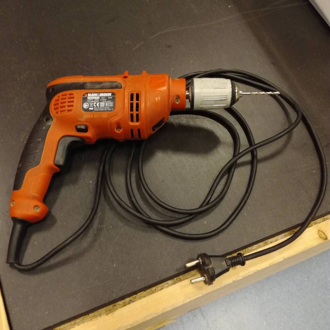
Drill Scan : obj file and texture