10. Machine Week
Assignment definition
Group assignment
Group assignment - design a machine that includes mechanism+actuation+automation - build the mechanical parts and operate it manually - document the group project and your individual contribution
Project definition
Our work is also documented in full on the group assignment page
We wanted to work on the Urumbu machine.
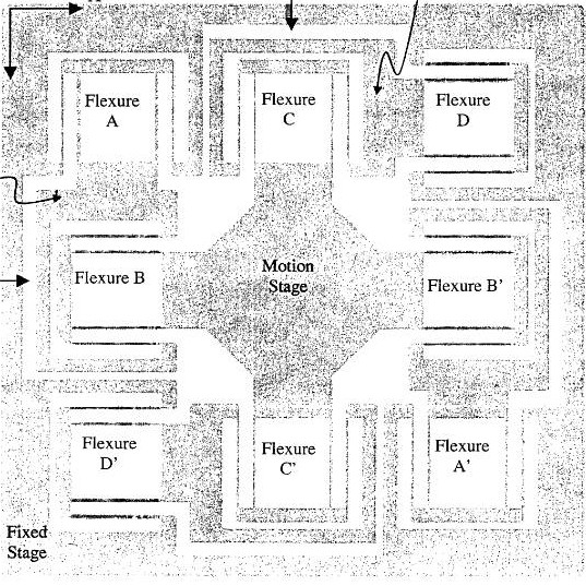
The goal of the Urumbu project is to make a high precision, very low cost machine based on flexures.
The advantages of flexures are numerous and include: * Wear free movement * Backlash free
Denis Terwagne had started by redesigning the design the XY stage inspired bythe MIT thesis of Shoryar Awtar (2004)
Last year, for their FabAcademy, Quentin Bolsée and Robin Wilmart worked on adding motors to the machine.
Robin ported the design to Solidworks but because of the very closed nature of Solidworks, I will go back to the OpenScad version.
Maxime and I discussed the things to improve:
- Mechanical Stability : No parasite motions.
- Actuation : Precise motion in X and Y in both orientation (+ and -)
- Improved Range of motion
Our first assessment of the machine made by Quentin and Robin was that there was quite some deformation, especially torsion of the central piece, and some parasitic motions.
Some of this parasite motion is due to the fact that the stage was 3D printed in PLA and thus has limited mechanical performances.
Differrent ideas were shared to fix that, including changing the design, annealing the 3D printed piece, chemically with a solvent melting or thermally using sand making sort of a mold and going in the oven, making it in another material by milling (polypropylene) or cutting it (laser-cutting or water-jet cutting).
Then the system used for actuation lacked negative motion because the springs they had used were too strong for the motors. Moreover, we wanted something very precise and 3D printed as much as possible.
We discussed inspirations such as the shaper actuation with cams, using a lead screw etc
Finally, we wanted to increase the range of motion as the stage build by Quentin and Robin is has a range of motion of 2cm x 2cm
We settled to separate the work, I would do the mechanical design for the first week and Maxime will do the actuation for the first week.
Then for the second week we might change place to make sure what we did is reproducible and well documented and to come with a fresh mind.
Flexure XY Stage
Mechanical Design
I need to do two things to move forward.
First is the analysis of the existing stage. The first ideas are :
- I noticed that Robin made some modifications to the stage and I see that they are the cause of some of the parasitic motions that we observe.
- Parallely, there are some unused space in the stage which we could take advantage of.
- Finally, some of the rods that are supposed to stay rigid bend when constrained so that needs to be fixed.
Secondly, before integrating the modifications, I need to learn OpenScad. I could redesign the stage from scratch but this is a highly geometrical and parametric design so I think OpenScad is the best tool for that.
On top of that, the openflexure microscope that interests me a lot is also designed with Openscad so I should learn it to contribute to that one as well. I will be reporting my learning of OpenScad in the CAD Week
Evolution and analysis of the past versions
Because the project started from a well documented thesis I skimmed through the thesis to understand the process that was followed to develop the stage.
Then let’s compare the 3 existing versions:
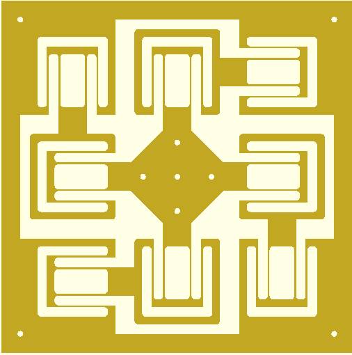
The first thing we see is the fasct that the stage links to the flexures became narrower for each new version. I guess that this is the reason for the torsion that we see when the stage is constrained.
To better understand the cinematic, I printed the stage of Denis to understand the modifications of Robin.
The reason he decreased the size of the links to the central stage is to increase the range of motion. Indeed, we see that the margin on the flexures has also been increased.
Regarding the design of Denis, we see that there is some dead space between each pair of parallel flexures.

The first things to improve is to take advantage of the dead spaces, increase some links dimensions to avoid them bending. We could also adjust the parameters to avoid losing space at the intermediate stage as it only travels half of the distance of the central stage.
Once that is done, we will actually be much closer to the original shape. However we will have the same issue that Denis and Robin worked to solve which is increase the range of motion.
Working with OpenSCAD
The first thing was to learn more about OpenSCAD. I followed a couple tutorials to understand how it worked and be able to play with it. Off course it’s not the best idea when starting with a new language to work on a difficult project, such as the Urumbu stage, at first, but I did it anyway even if that was a bit hard.
I started off the OpenSCAD code from the Urumbu repo.
Making sense of the code
Understanding OpenSCAD syntax is not super difficult even if it sometimes confusing because you only see :
translate([x,y,z])
cube([x,y,z])
rotate(angle,[x,y,z])
So the first thing I did was to work on making it simpler: I added comments and functions to make the code shorter and easier to understand.
Functions are a way to add some abstraction. It is very useful when you want to do something repeatedly. Specifically, it can be useful both for the programmer but also for the reviewers, because they only need to understand specific instructions once and then everytime they see that function called they will know that this action is applied.
Comments are also key to understanding a code because the code only gives you the functional short-term intent of the programmer, while comments can tell you why he did that and how that combines with the rest of the “story”.
Files
Navigating in OpenSCAD
With a refactored code, it was much easier to navigate and understand how to change the parameters and optimize the shape.
Hozever this was really difficult, even with a refactored code.
The fact is that OpenSCAD does not have a real time rendering that properly shows you what is happening, actually that is not true for addition of material but in this case I was mostly removing materials and it is not easily visible.
On top of that, you cannot take measures in the viewer, or at least, I did not find how to do it. That means that you only have access to the measurements that you compute and not to the ones that are “geometrically computed”.
What I mean by “geometrically computed” is the following : Using geometrical constraints (parallel, perpendicular, symetrical, rotation, …) and measurements (length, angles, …) you can make computations and using the measuring tape, figuratively or physically, you can access the result of this computation. This is partly how we build mechanical computers.
This makes it much easier to understand the link between different parameters, off course the other way to do it is to be amazing at visualizing stuff in 3D but it is also exhausting.
Long story short, you can only visually assess the result of your sketch in OpenSCAD.
The second thing is that the approach to construction is very different. You cannot simply add a sketch on an existing face. You have to start from the absolute origin and find a way in the rest of the code to move you shape to the place you want. You can reuse existing translations and rotations to get there but that could lead to difficult to understand steps because construction instructions are then no longer grouped by use but by position.
Optimization
I played with the parameters and managed to improve the design a little but also realized that to improve it for real I would need to change the construction hierarchy by removing some translations and rotations, changing symmetries etc.
Because I was not confident enough or fast in OpenSCAD, I decided to start it from scratch in Fusion360. However, contrarily to Robin, I did not want to start from a profile of the OpenSCAD design but rather redraw it to be able to optimize it better both in terms of construction clarity and to maintain the symmetry.
Stage Optimization in Fusion360
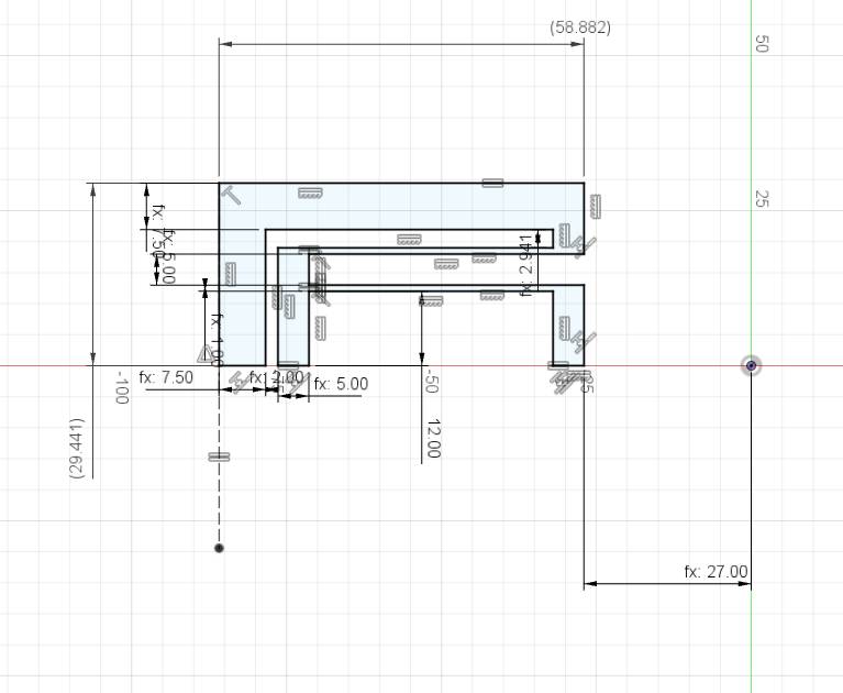
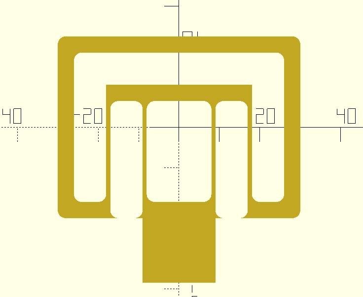
After having redrawn it in Fusion360, I reused the original parameters from Denis’s design (beam length, beam width, …). However, I wanted some parameters to be dependent on the others in one way not the other.
For example, I wanted to make the leading parameter the spacing for the flexure. The spacing is also the variation in position that the stage can achieve in one direction, so that the total range of motion is double the spacing.
Using the spacing as a key value in my design is very important because the space I need to leave free to avoid collisions must also be of this dimension at least.
I had managed to get a 7mm spacing to fit in the 3D printer plate (20cmx25cm) which means we had 14 mm range of motion.
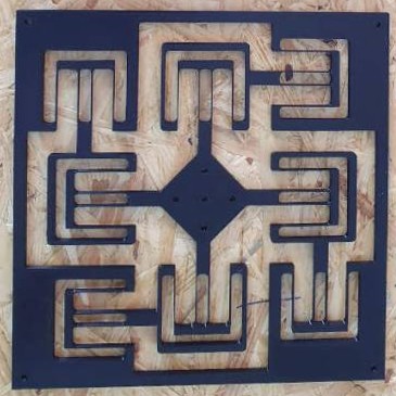
I improved different other features and then 3D printed a first version.
I tried to 3D print it with a full infill because I believe that it would be interesting for the mechanical properties of the flexures and the stage but it did not turn really good and actually I think that it makes it more long term plastic deformations.
Also I had not solved all of the issues, especially the lateral bars of the flexures where not as thick and rigid as they could be given the design so I went back to the drawing board and to Fusion360 and improved that as well.
The timeline of the Fusion design is not really clean because of that modification but it was the most convenient way to do it.
Actuation integration
Shorya Awtar’s development
We found a Youtube video of the original author of the Urumbu XY stage, Shorya Awtar, that is still working on it and managed to build a machine that has a range of motion of > 10mm with a resolution of a nanometer which is completely crazy ! The current system is described on the University of Michigan website and described in the video below.
However, it is built in steel thus it is more stiff and also he can make a piece much wider area where we are limited by the size of the 3D printing plate, which is roughly 20 cm by 25 cm, so that we can only fit a 20cmx20cm square.
Placing the pins and drawing the spirals
For the actuation, Maxime decided to make spirals that we could prototype in the lab so that we would nearly only use the motors and build all the other components.
The first spirals and pins that we made were really not succesful.
The pins were in direct contact with the spiral and the spiral was 3D printed so the result was nothing was moving.
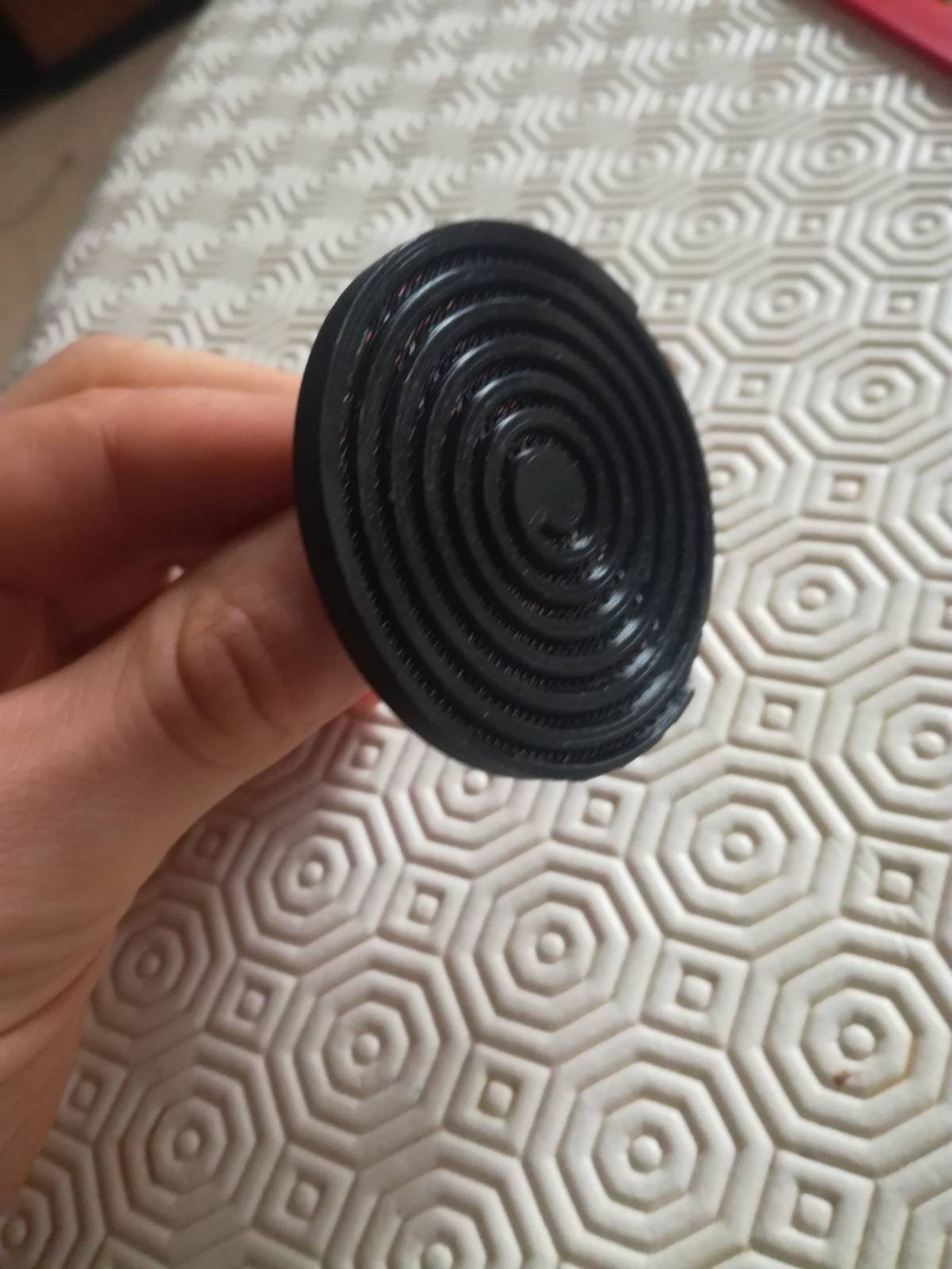
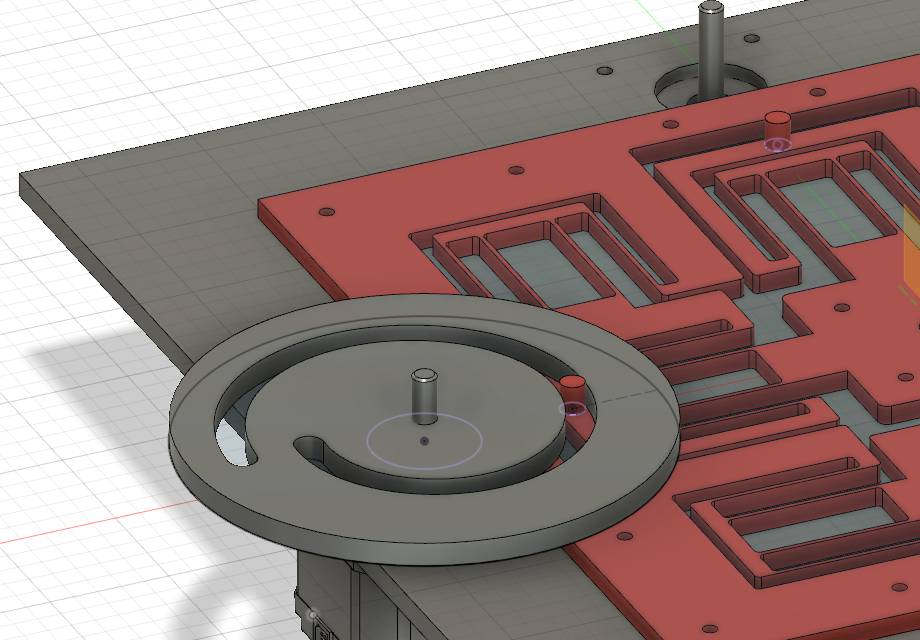
Therefore I added pins going out of the XY plane that could move in the spiral actuator that Maxime was designing. At first, I was concerned to add pins only on top of the stage because that could lead to some torsion but it would be small enough so we accepted it.
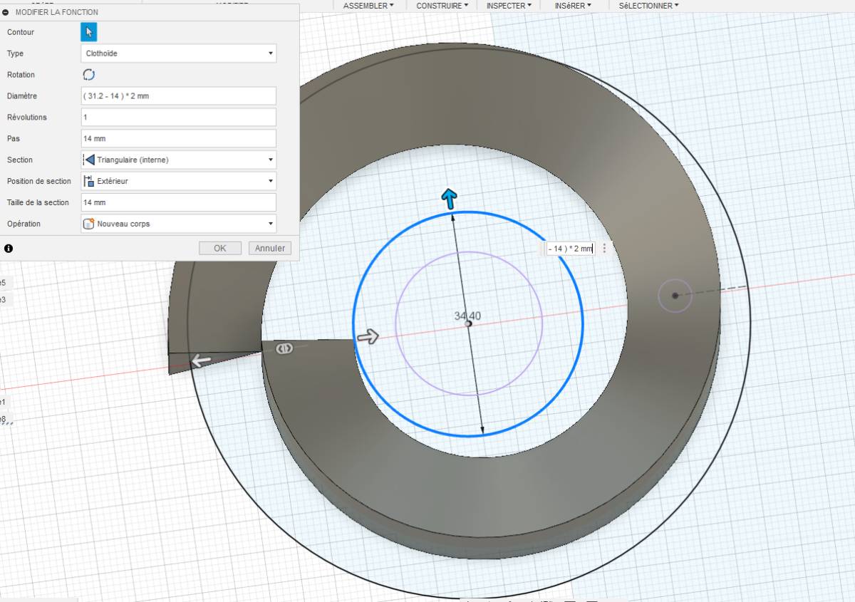
We 3D-printed the spiral but realized that it was not a satisfying mechanical model as there was too much friction.
The second question was where to put the pins on the flexure. I hesitated between a central position which is more narrow but symmetrical and putting them on the side which keeps it on a wide area so stresses are more distributed but we lose the symmetry.
We decided to go for the symetrical center position for the pins.
The Motor Controllers
Quentin’s Fab Step I2C
We wanted to integrate the motor controllers designed by Quentin which are still under development. Therefore, we worked together to understand it and integrate the different motors together.
The motor controllers are described here.
The solution concept is the following :
- Controllers are identical.
- All motors controllers are communicating on a single bus and receive instructions based on their address.
- Motors controllers are self addressed : This means they know their position and address from their position in the connection chain. This means that all motors can be replaced or swapped, and from their new position, they will receive a new address.
- The instructions are provided to one node through USB and propagated to the other ones.
The advantage this brings is that : 1. You are not limited by a maximum of motors and you don’t to define which motor is which connector, provided that they are connected in the right order. 1. You can place the central controller (computer) wherever you want and connect any motor so you don’t have a lot of cables running around your machine.
Understanding
The first thing I wanted to understand was what can be found on the board of the motor controller.
So what functions does it serve :
- Control : Instructions interpretations
- Motor Power control: Stabilize the power for the motors
- I2C communication : for the dispatching of instructions
- USB interface : to connect to the computer
- Serial connection: For the creation of the addressing mechanism each node receives data from the previous one and transfers data to the next one.
The components to answer these needs are :
- Control : the microcontroller used is a SAMD21E17
- Motor Power control : 2 H bridge (1 for each of the two wire loops)
- I2C communication : One I2C interpreter, One opto coupler-like device with current amplification possible.
- mini USB connector : with the SAMD21E17 supporting USB connections
- Two connectors for input and output and outputs of power and signals
- Plenty of capacitors to dampen the voltage variations and provide current buffers
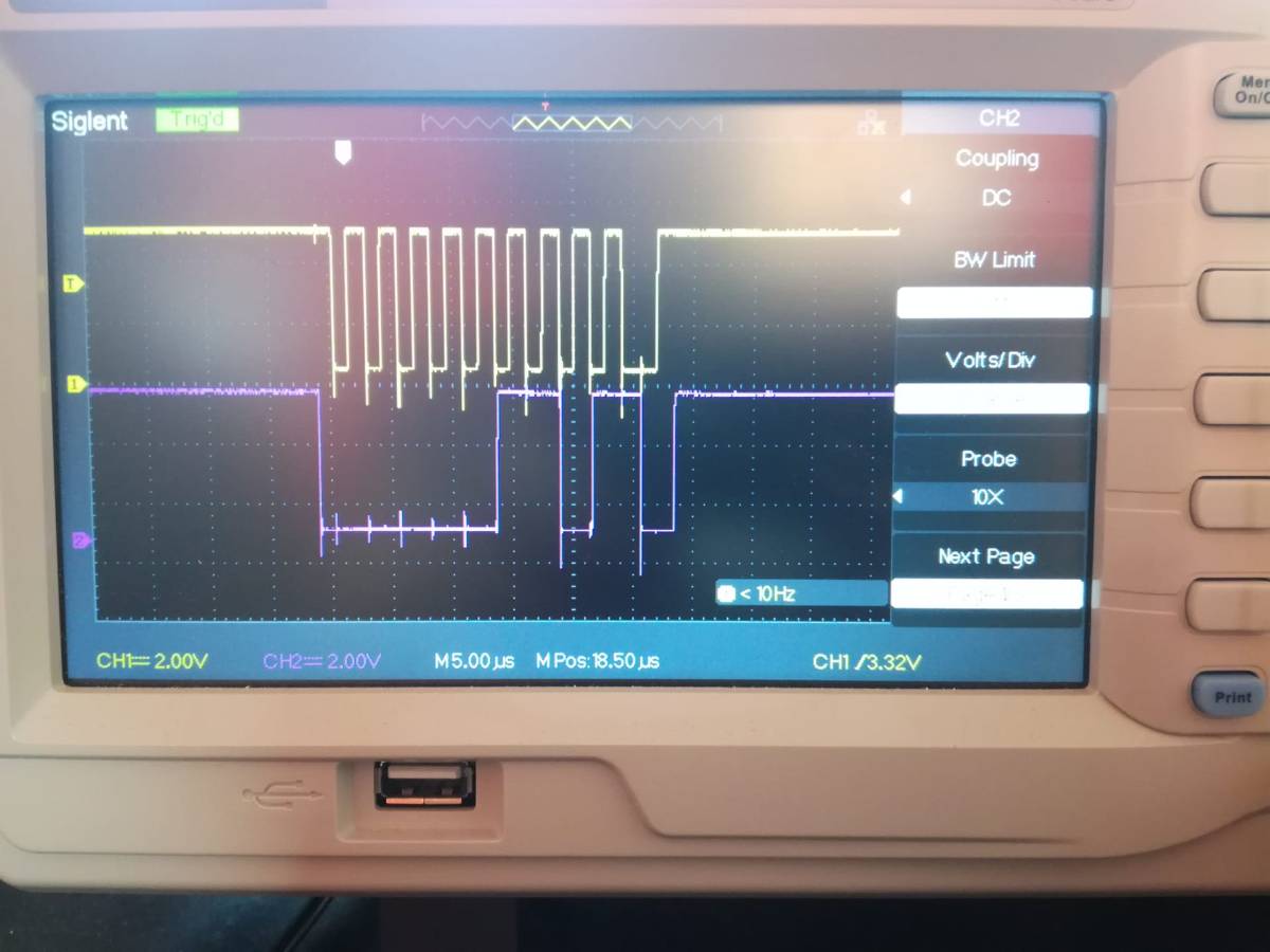
Development
We tested together with Quentin the I2C communication between machines and decoded it on the fly using the oscilloscope.
However we were not very familiar with the set up of the I2C communication library so we had to check how to set it up as we did not get an answer from the slave nodes.
Global Open Time
During the Global Open Time, I had very interesting discussions with Rico and Dan about alternatives to the spiral design for example using a connecting rod.
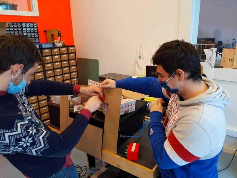
Assembly
To get a single well fitting assembly, I drew all the assembly components in Fusion360.
I did not add the screws because I did not know which ones we add, that was a mistake that we had to treat manually afterwards.
Also because Quentin’s motor controllers were still under development I did not have their exact dimensions and underestimated them by 5mm which is a shame… Fortunately, we found some off the shelves rubber feet that we added below the 3D printed ones and it went fine.
We assembled everything and realized some limitations the project had:
- The pins we used are very thick (5mm) because that is the internal diameter of the Teflon rings. The problem is that given the constraints on the diameter of the spiral, we can only make 360° rotation and that limits the resolution of our machine.
- The fixation holes of the motors one the flexure stage should have let the screws go through because the blocked the spiral.
- The feet should have been taller than the controllers mounted on the motors.
Overall it worked so it’s not so big of a deal.
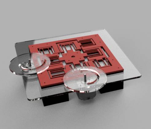
Here is the rendering of the Assembly
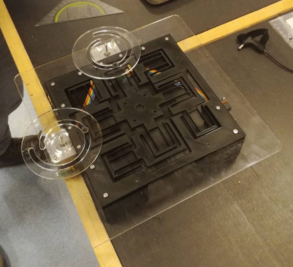
And it works !
The Automated blinders project
We also made a second machine that closes blinders automatically because we were waiting for Quentin’s controllers.
Our first idea was to measure the sun orientation using the shadow but now the goal had been simplified to measuring the sunlight height only. You would use the machine by placing the sensor on the bottom part of your computer screen and activate the device. Once that is done, the blinders close until the sun shines just below your screen so you still enjoy it but you can still work as it does not reflect on your screen.
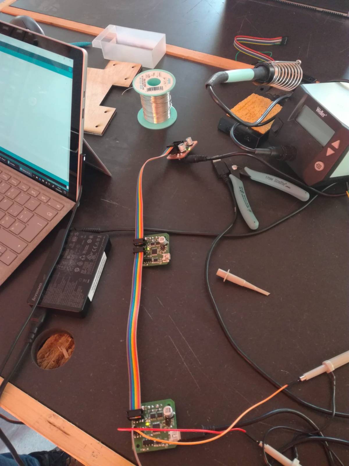
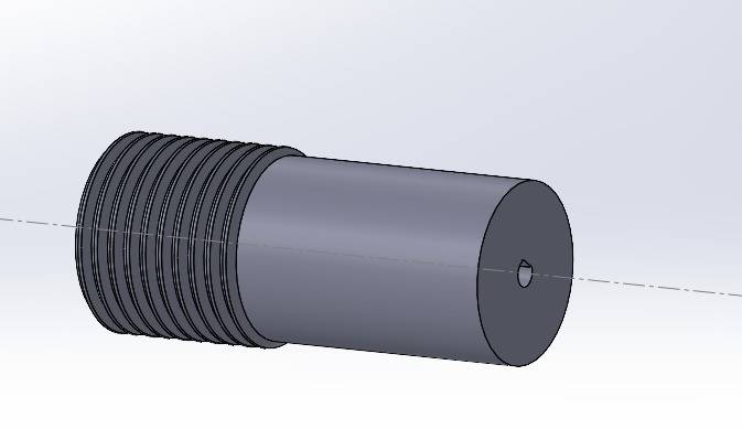
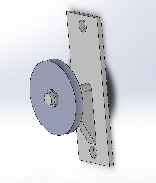
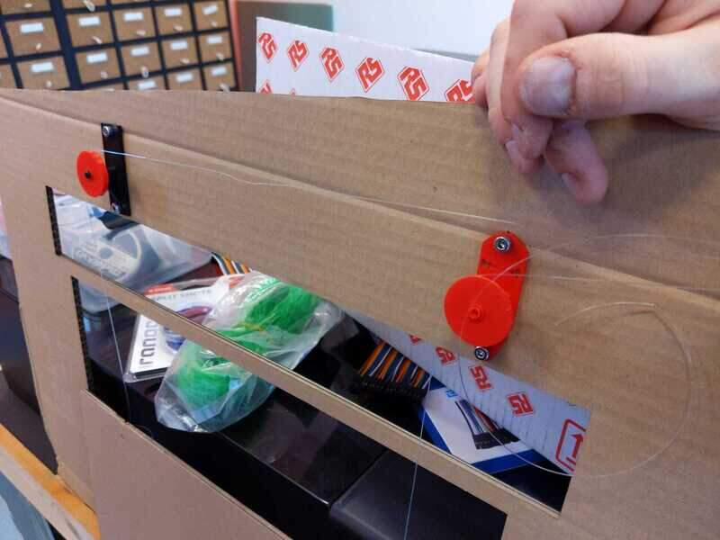
To build it, Maxime designed a capstan to make roll the wire around, and a pulley and pulley holder. I designed and milled a board containing the detection of the sun using 2 phototransistors and resistors.
Photodiods and phototransistors
Photodiods act as a switch enabled by light. When there is light, the photodiod is activated and lets current through.
But actually calling them photodiods is wrong because if they were, they would barely let any current go through because they would let only one electron through for each photon that they receive which is very inconvenient. To counter this, they are actually coupled to a transistor which makes it possible to add a gain to the current output by the photodiod.
To make the detection, I needed a clear base value and I wanted it to be logical, when there is no light, the signal should be zero. Therefore I pulled down the pin connected to the Arduino with a 10k resistor.
Then to measure the amount of light incoming, I added a pull-up enabled by the phototransistor. When the sun shines, the current flows through the phototransistor and increases the voltage measured at the resistance. The resistance enables us to measure the voltage that “goes through the phototransistor”.
Regarding the components, I decided to go for the PT15 21C because we had them in the lab and that they don’t have a Infrared (IR) filter and that it would enable us to discriminate between artificial light (often LED which is nearly purely visible) and sunlight which has a much broader spectrum from UV to Infrared.
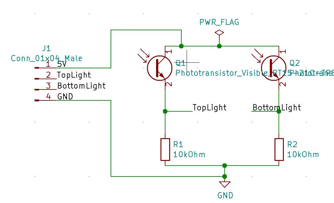
Regarding the PCB layout, I designed so that the headers would not be in the way of the light so not in between the phototransistors and that the distance between the two would be 2 cm which allows for some resolution of the system while resisting some “blurryness” in “distributed” sunlight conditions such as when it is cloudy as it often is in Belgium !
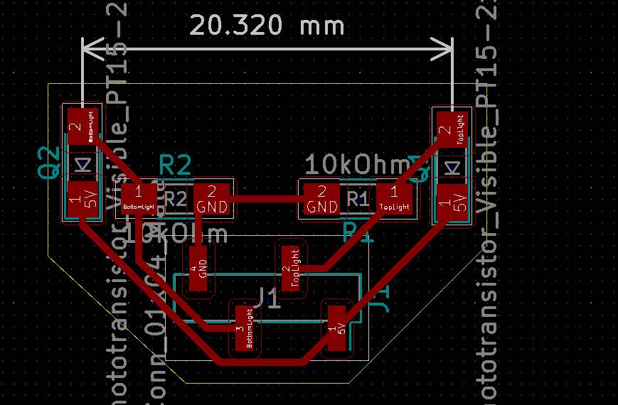
One thing I didn’t think of was to put the headers horizontally instead of vertical
Mechanical design and assembly
Max brought a motor and a controller and we connected it all using an Arduino.
The most difficult part of that project was getting some sunlight because between the start of the project and now the weather went from sunny summy to snowy winter.
On top of that the blinders in Max’s office were not installed so we made a model of them which proved very time consuming.
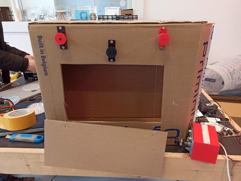
We used nylon wires to fix the blinder to the cardboard frame and it was a mess.
Testing
Because of the lack of IR in artificial light coming from LED, we had to go to the window. We first believed that the doubled glazing was reflecting IR so we tested first with the window open. Off course there was some wind so the blinder was moving …
However that was actually some nice test to visualize its movement !
Here we see that the vertical movement of the blinder is actually following a sine wave and we could even measure its frequency !
The effect of the wind is also something that we should consider when building the actual full size machine, because when it’s sunny it’s often hot and you open the windows !
We got the motor working …
… and captured its effect on the signal in real time.
Files
Urumbu
- Motor Holder Stage to Laser Cut
- Spiral to Laser Cut
- Feet to 3D print 4 times
- Flexure XY stage to 3D print
Blinders machine
- Phototransistors Gerber files
- Kicad Gerber files