13. Output Devices
Assignment definition
Group assignment Measure the power consumption of an output device
Individual assignment Add an output device to a microcontroller board you’ve designed and program it to do something
Group assignment
We tested the consumption of output devices on Max board using a power supply.
It’s also possible to do it using a shunt resistor meaning using a resistor on which you know the resistance and which resistance value in negligible, placed in series with the component you want to monitor and calculating the peak consumption based on Ohm’s law: V = RI.
The group assignment is described here
Individual assignment
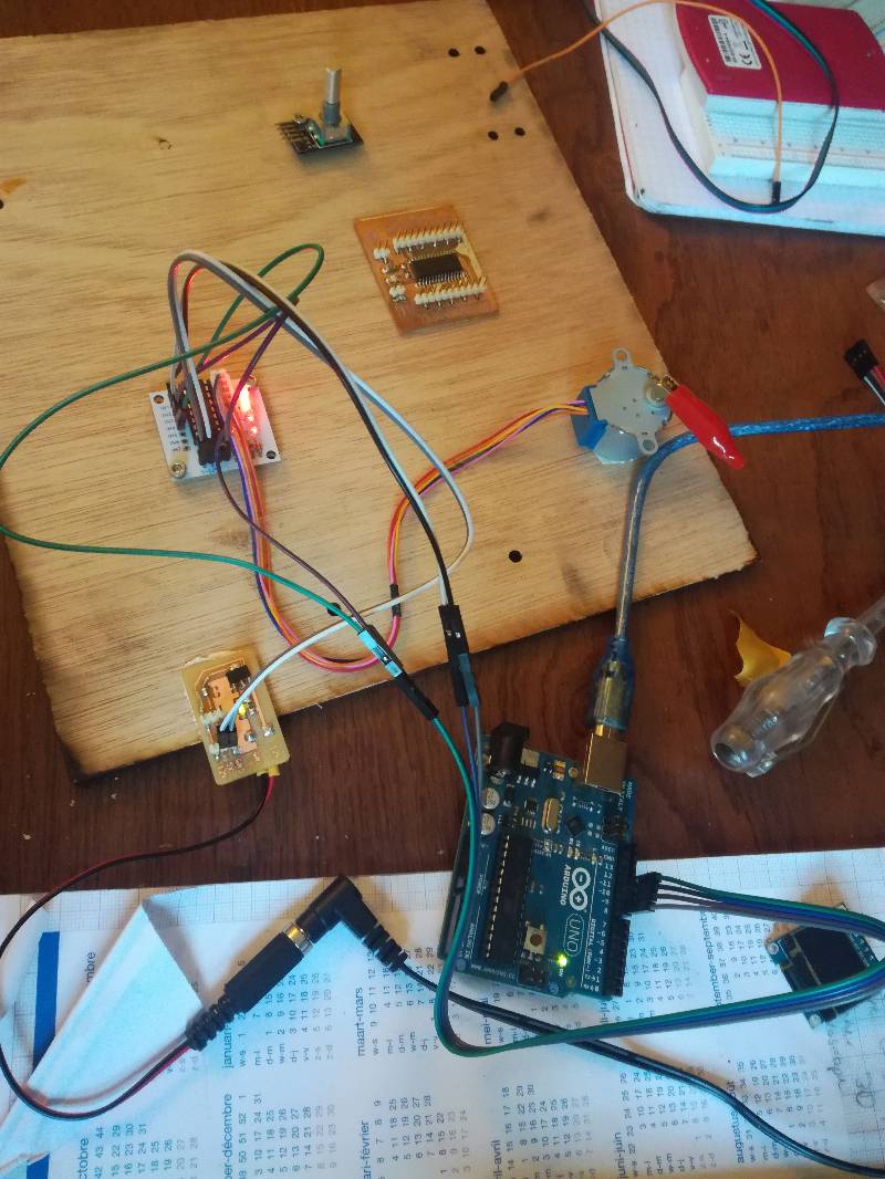
Testing the components
So I tested different components that I wanted to integrate in my final project with an Arduino to see if I could get them to work and I did: * the OLED screen * the Servomotor S90 and the rotary encoder * the stepper motors 28BYJ-48 with the driver board ULN2003
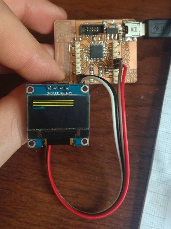
OLED display
I used an I2C OLED screen which will be perfect.
The goal was just to see how it worked not to program anything fancy as I wanted to focus on working on the board for the final project.
I used the Arduino to control it to quickly connect it but I want to test later with my CircuitPython dev board using the SAMD21E18.
Controlling the SSD1306 with CircuitPython
That’s done. I have made a board that run CircuitPython on a SAMD21E18.
To get it working you need to install the appropriate libraries.
One nice way to interact directly with the screen is to use the python interpreter by connecting through the serial port.
I am running Ubuntu so I used the following command but here are other ways to do it. To do that on Windows, you can do that with Putty.
cu -l /dev/ttyACM0 -l 115200
~.
Once that is done, I can test my code interactively and then I just dropped the code.py file on the SAMD21E18 and it ran.
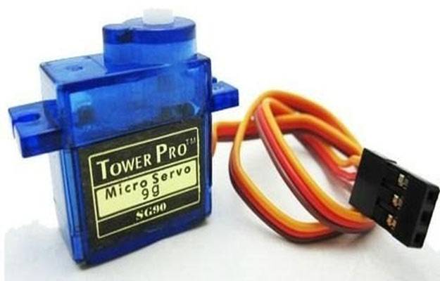
Servomotor S90
I tested the Servomotor I had on hand with the Arduino library but unfortunately, it seems mine is broken.
It did turn once but no more after the first movement which I found really weird.
It was only turning in one direction,which completely defeats the use of a servo and nearly always got stuck during the first rotation. I tried to change the limit values to avoid it getting stuck at 00 or 180° but it did not work and the behavior was still very weird, so I’ll investigate that deeper.
/ Include the Servo Library
 #include <Servo.h>

 // Rotary Encoder Inputs
 #define inputCLK 4
 #define inputDT 5
  // Create a Servo object
 Servo myservo;

 int counter = 0;
 int currentStateCLK;
 int previousStateCLK;

 void setup() {

   // Set encoder pins as inputs
   pinMode (inputCLK,INPUT);
   pinMode (inputDT,INPUT);

   // Setup Serial Monitor
   Serial.begin (9600);

   // Attach servo on pin 9 to the servo object
   myservo.attach(9);

   // Read the initial state of inputCLK
   // Assign to previousStateCLK variable
   previousStateCLK = digitalRead(inputCLK);

 }
  void loop(){

  // Read the current state of inputCLK
   currentStateCLK = digitalRead(inputCLK);

   // If the previous and the current state of the inputCLK are different then a pulse has occured
   if (currentStateCLK != previousStateCLK){

     // If the inputDT state is different than the inputCLK state then
     // the encoder is rotating counterclockwise
     if (digitalRead(inputDT) != currentStateCLK) {
       counter --;
       if (counter<0){
        counter=0;
       }

     } else {
       // Encoder is rotating clockwise
       counter ++;
       if (counter>180){
        counter=180;
       }

     }
     // Move the servo
     myservo.write(counter);
     Serial.print("Position: ");
     Serial.println(counter);
   }
   // Update previousStateCLK with the current state
   previousStateCLK = currentStateCLK;
 }
The servo makes the first rotation than stops…
Stepper 28BYJ-48
Alimentation
I started by making an alimentation board that I milled than broke than milled again then broke again.
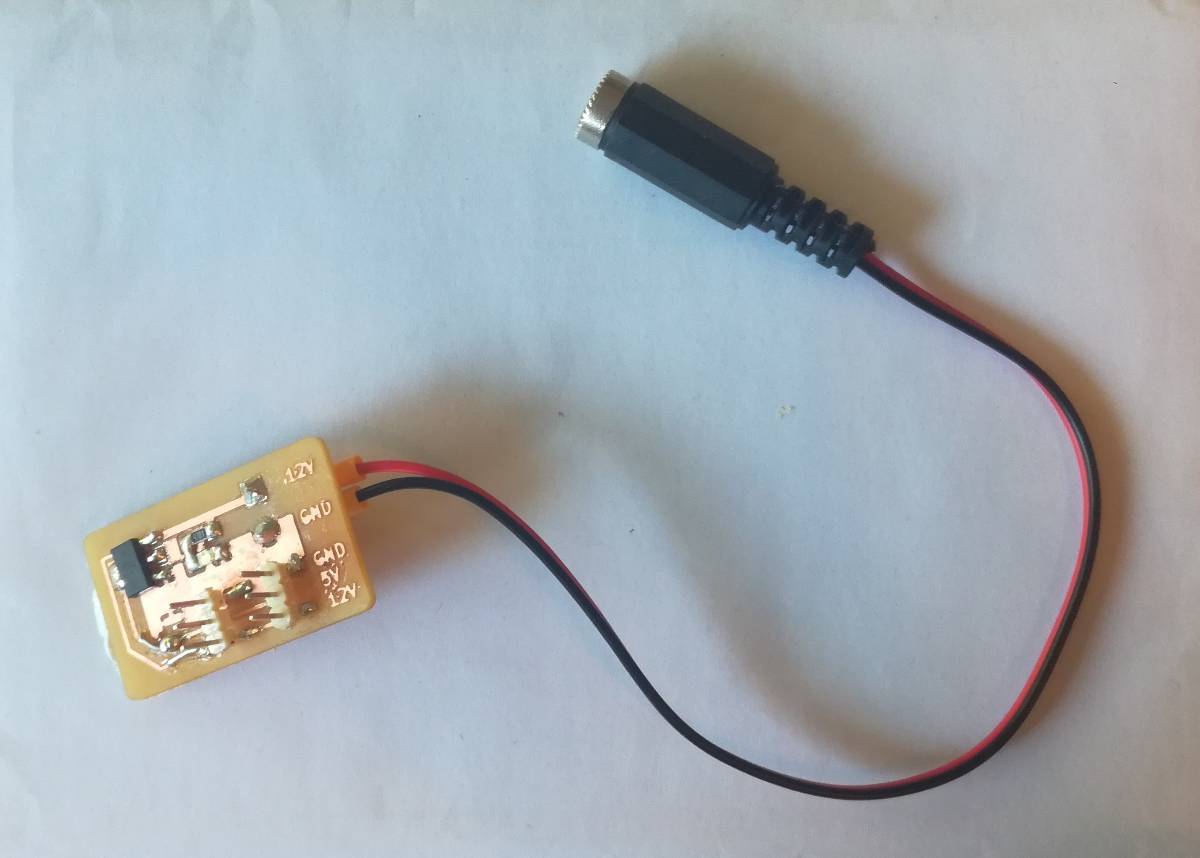
The first goal was to have a general alimentation able to deliver 12V or 5V to 3 connection. But my design was not ideal so the first headers broke the connection which I had to fix. It still worked.
That was also the first time I made drill holes in my board so I had to export the drl files and use them in Bantam Tools which was very easy.
To export the files, you just have to click on “Generate drill files” in the “Plot” menu that you use to generate the Gerber files.
With the alimentation board and a 12V AC/DC converter, I could now power my motors.
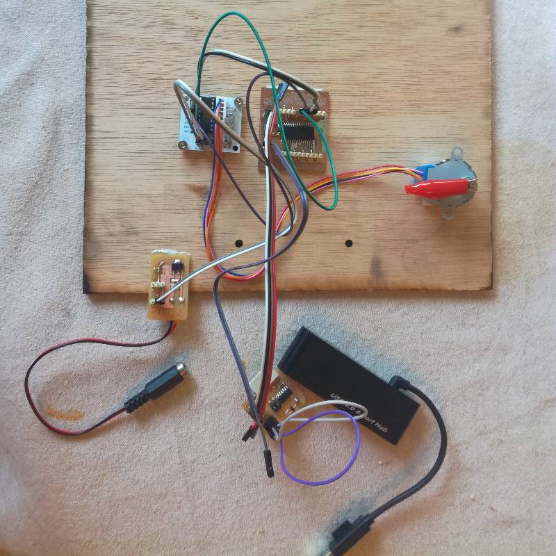
I first tried with the Arduino as I had no easy way to get a serial output to my computer using the AVR128DB28 board I had made and wanted to program this week.
I powered the 28BYJ48 stepper which is a very cheap stepper motor than runs on 5V.
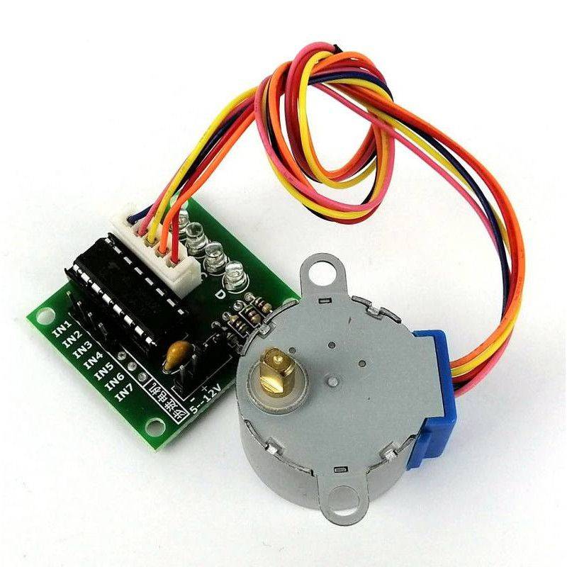
With Arduino
It worked fine using the Stepper Arduino library but I want to get rid of that later because I don’t like the fact that it’s “hiding” so much of the actual actions. On top of that, when I was limited speeds of 15RPM which is quite slow, good thing I chose stronger motors for my project.
So I moved on to connect it to the AVR128DB28.
With AVR128DB28
Connections
Before doing that, I checked the power requirements of the AVR128DB28.
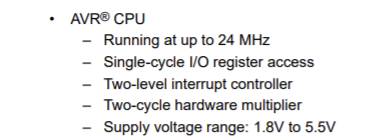
That reminded me of this incredible flexibility of the AVR family regarding power !
Now let’s check which pin I should use thanks to Spence Konde porting to Arduino.
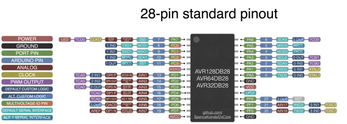
With that done I went into connecting it and programming it.
Programming
To do that, I checked the datasheet of the 28BYJ48 to look at the Gear reduction and steps per revolution, I updated the pins and uploaded it through my Samd11c14 based UPDI programmer.
#include <Stepper.h>

const int stepsPerRevolution = 32;  // the number of steps per revolution
// for your motor
const int GEAR_RED = 64; //Gear reduction
const int stepsPerRevolutionOut = stepsPerRevolution * GEAR_RED;
// initialize the stepper library on pins 13 to 16 of the DXCore by Spence Konde:
Stepper myStepper(stepsPerRevolutionOut, 13, 15, 14, 16);

void setup() {
    myStepper.setSpeed(15);
}

void loop() {
//  Serial.println("clockwise");
  myStepper.step(stepsPerRevolutionOut/4);
  delay(500);
// step one quarter of a revolution in the other direction:
  myStepper.step(-stepsPerRevolutionOut/4);
  delay(500);
  }
I used the DX_Core that you can add using
http://drazzy.com/package_drazzy.com_index.json to your Arduino preferences.
Downloaded the “DxCore by Spence Konde” library and sent my code using pyUPDI option.
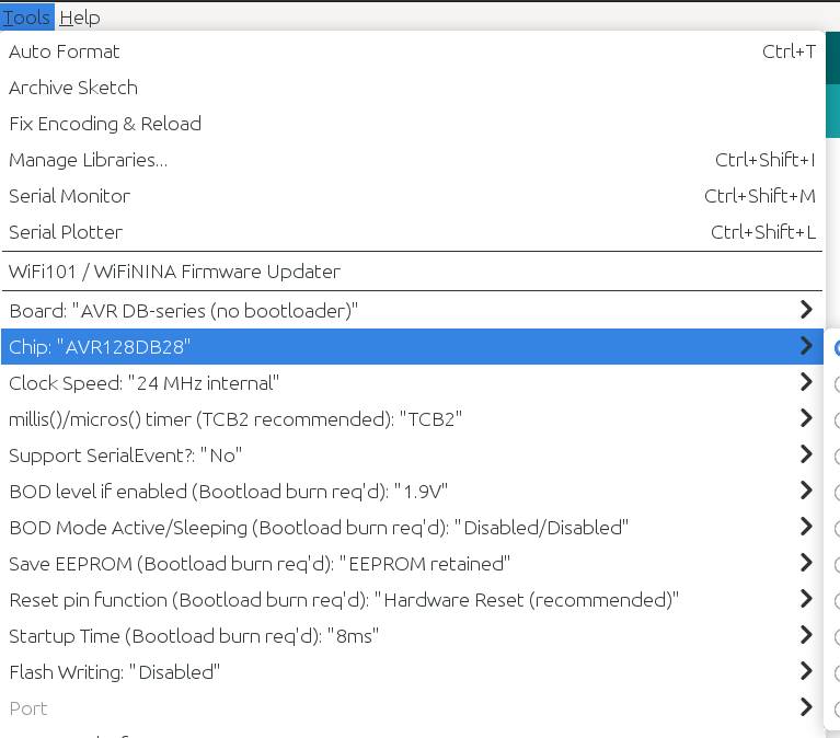
That worked and it’s now good to go !
My objective : Control board for my final project
My final project is progressing and I need to update its documentation. I decided to make a revisited version of Quentin’s photogrammetry scanner that is portable and easily stored.
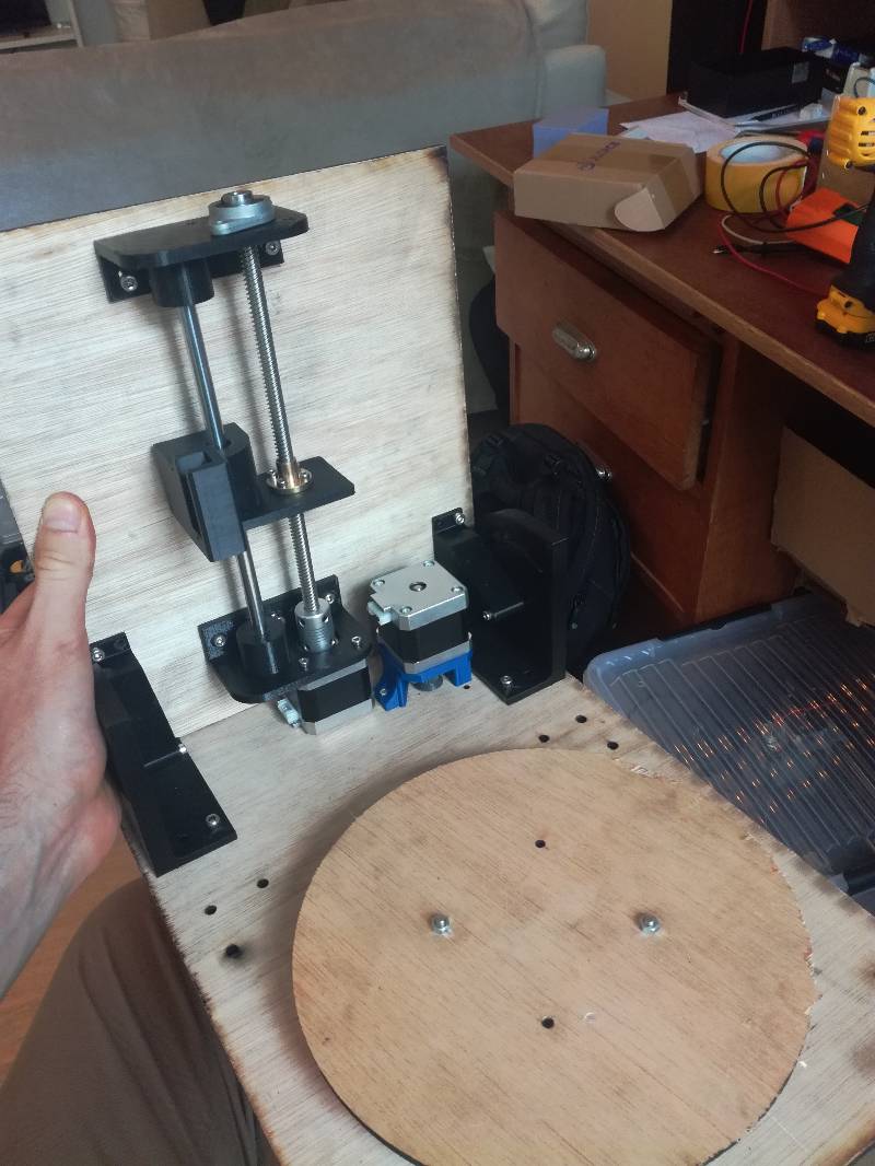
Controlling the motors
I want to control 2 steppers and 1 servo.
Using Pololu driver boards to control the to control two NEMA 17 steppers.

and a Servo S90 to control the angle of the camera.
Interacting with the device : Display and controls
I want to use one OLED screen to show the progress of the scan and a rotary encoder to interact with the scanner the in a similar way we do with 3D printers and as I will also use the ESP32-Cam I want the control to be possible through Wifi.
Therefore, I will use a Serial interface between the ESP32-Cam and my microcontroller.
The microcontroller : SAMD21E17
To do that I decided to use a SAMD21E17 as it has a native USB port which I find very convenient and enough pins to drive all I need for my application.
Ok that’s a lot to cover since I have barely worked with any of these component for the moment.
To begin, I tested all the components individually. I will still have to program them to do what I want later.
I designed the schematics and routed the PCB but it took me quite a while and I did not have time to actually mill the board stuff it and program a basic movement to fulfill the assignment requirement.
Pin out and schematics
To design this I took much more time than for the rest of the assignment, because I wanted to have an I2C and a serial connection to the ESP32-Cam I had to know what pins to use and also a PWM pin.
To do that I dived deep in the datasheet first but some things were not clear. Reviewing that with Quentin, we went to look at the Arduino porting by Mattairtech directly to find out what are the defaults port.
If you never did this, I advise you to try ! It looks very hard to understand because it’s hidden from general users but actually reading it makes some obscure conventions much clearer and makes you more knowledgeable in the microchips you use.
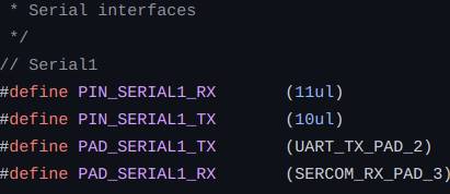
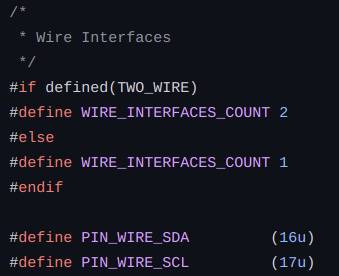
The pinout on the Mattairtech port is actually clearer than in the datasheet.
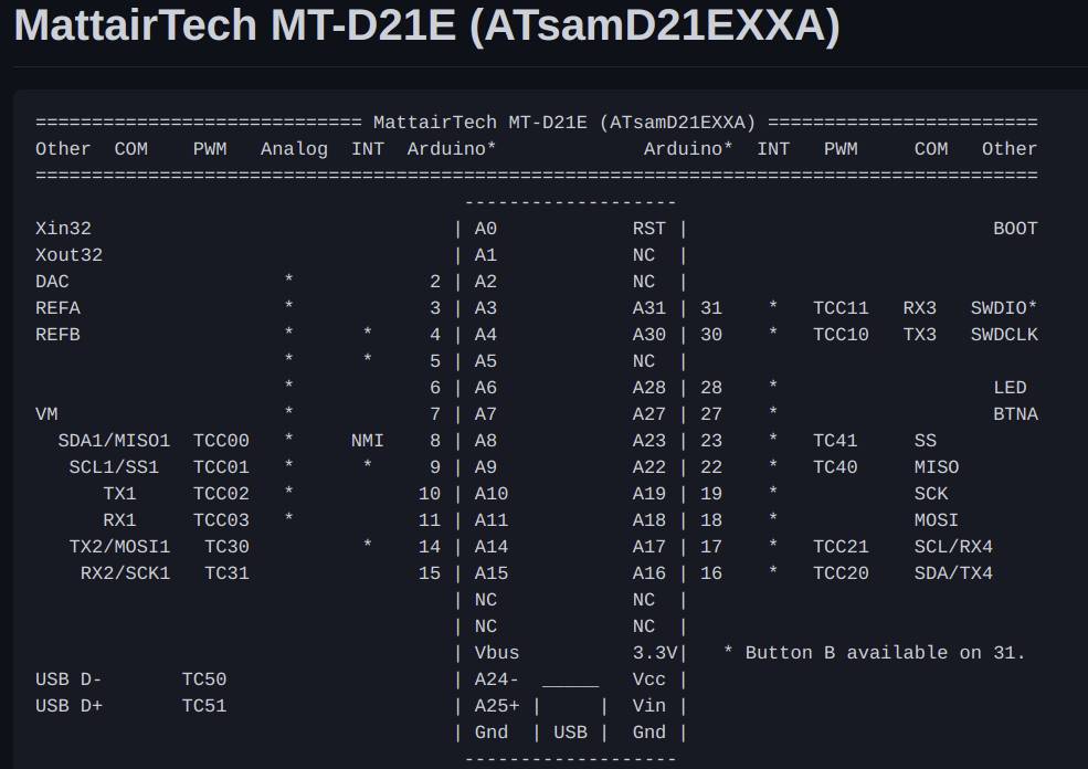
Knowing the pinout, I drew the schematics and moved on to routing.
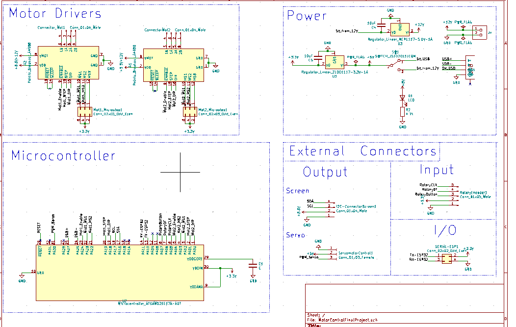
Routing
Routing was easy for all the circuits I did before because they were super small. This time it was much bigger. So I started by subcomponents and I went through the different components one at a time.
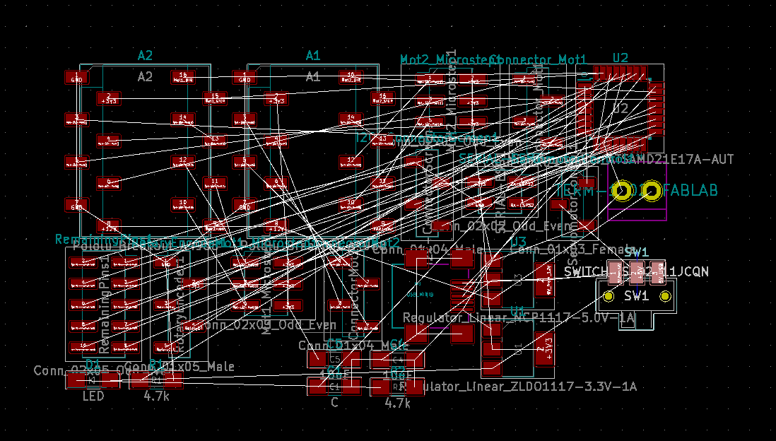
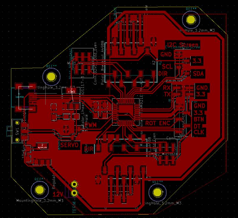
The final result is clean enough but I will probably make some more changes before producing it.
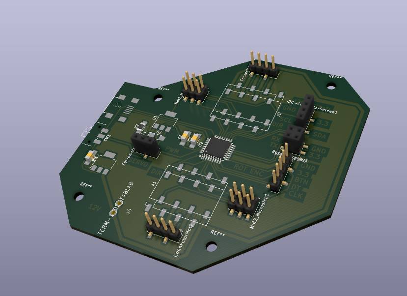
Making a large circuit like this one made me learn a lot about how to approach the design.
Files:
- The board for my Final Project
- The stepper code for the AVR128
- The demo Arduino code for I2C screen control
- The rotary Encoder and Servomotor code
- Python files and libraries for OledSS1306