14. Networking and Communications
Assignment definition
Group assignment
Send a message between two projects
Individual assignment
Design, build, and connect wired or wireless node(s) with network or bus addresses
Research
A good start to understand communication and networking (communication with more than 2 parties) is to learn about the OSI Model.
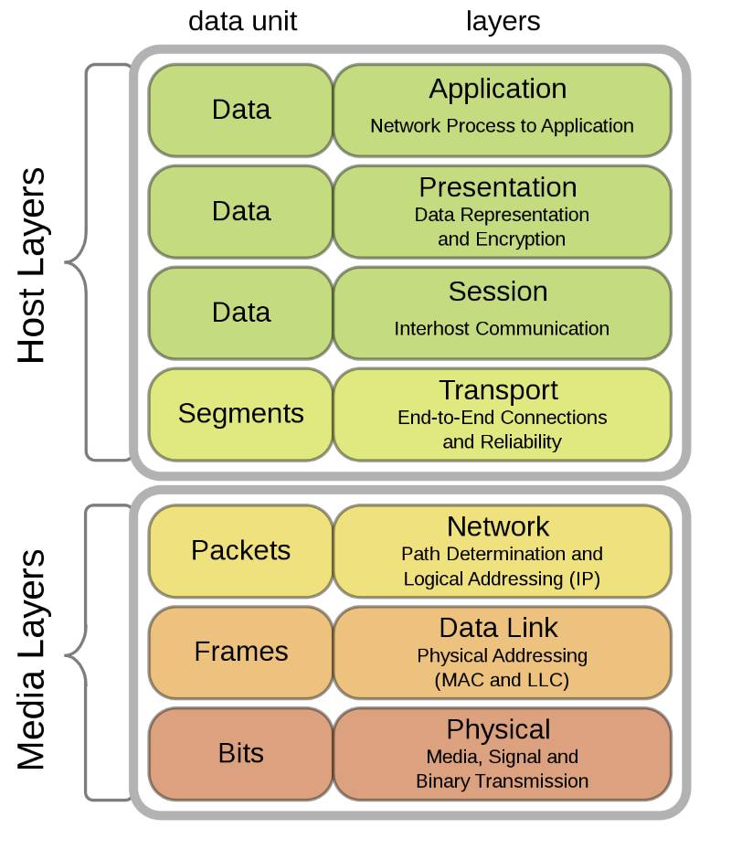
OSI stands for Open Systems Interconnection, it divides the communication activities in different layers of abstraction.
For each level, some decisions are taken as to how one function will be performed.
Physical Layer : the Bit
The first decision is about physical mean of communication meaning, the type of physical interaction (electricity, pressure, light, E-M waves, …) and medium of transport (copper, air, water, void, glass, …).
Then we must decide to corresponds to a unit of communication, in binary that’s a bit, a 0 or a 1.
For a letter, the physical layer is paper and ink and the symbols are defined as shapes of ink (so called letters) on the paper.
Data link Layer : the Frame
Once that is fixed we move onto the Data link layer. The data defines the frame.
The data link ensures transmission of data frames between two nodes connected with a physical layer.
Once you know how you communicate physically, you must know discriminate between a message and random activity on that line.
That is the goal of the Data link layer, it ensures a reliable communication.
It defines the beginning and end of a transmission or message.
That is equivalent to the ringtone of the phone, or your mother calling your name before telling you something. First, you grab your interlocutor attention and make sure they are hearing you properly and then you start proper communication.
In the case of a postal letter, the envelope is part of the frame. It clearly defines the message as being whatever is inside.
Network layer : the Packet
So know we have a mean of communication and controls to make sure it arrived safe.
We must package the message and make sure we send it to the right place.
The network layer ensures that messages arrive to the right host.
For example, the network layer is the part including your postal address.
On the internet, that is taken care of by IP addresses (Internet Protocol).
For good addressing, the addresses must be univoque which means that there is every host in the network must have a unique address that determines where it is.
We can build addressing using hierarchical systems and omit certain part of the address and define the missing part as a default depending on the sending host.
For example :
- Harry Potter : To send a message to someone in your house, the name is sufficient
- Harry Potter, Privet Drive 10 : For all people living in Harry’s neighbourhood or even in London that might be sufficient.
- Harry Potter, Privet Drive 10, London : However there might be a Privet Drive in Dublin as well so if you send a message in the British post it is important to precise which Privet Drive you mean.
- Harry Potter, Privet Drive 10, London, Great-Britain : Finally, there might be multiple London in the world so it is important to precise the country if you send via international post.
Message forwarding
You can also have sub-addresses which means addresses that are valid only in the local network, this is what VPN (Virtual Private Networks) do.
Your home internet router does that, it gives you an address in your home network and sends requests out into the world that are to be answered to him.
However, the host answering does not know who it is talking to inside your home network because your router is forwarding the received message back to you but from the outside the message could go to anyone in the local network.
VPN and TOR (The Onion Router) work the same way, request come out of a node but this node hides many many different hosts thus it is virtually impossible to know from whom it came from thus making the request anonymous.
Transport Layer : the Segment/Datagram
So the first layers were about how do we transmit the message (physical layer), what is a message (data link layer), how do we address a message (network layer).
The transport layer is now there to answer the questions how do we divide the message into sendable packages and bring them back together.
Very quickly, the message becomes too complex to be sent and it becomes critical to divide it into pieces.
There are many ways to divide a message and thus many transport protocols such as UDP (User Datagram Protocol), TCP (Transmission Control Protocol), …
Now, imagine that you can send only one sentence at a time through the post but you want to send ten pages of text.
How would you make sure the message is clear when it arrives ?
Some letters could be lost, some damaged or it could arrive in the wrong order, or maybe you “break” the post office because you send to many letters at the same time, …
The network layer exist to solve these issues. It may cover the following services :
- Same order delivery: Numbering your letters could make sure they are read in the right order
- Checksum: you can verify that the message was not corrupted by looking at the writing of the sender.
- Flow control: In a phone conversation, if you counterparty speaks to fast you might not understand everything, flow controls regulates the flow of information to make it manageable.
- …
Data Layers : Session, Presentation and Application
Above the transport layer, we can send and receive proper messages but we might want additional features to make it faster, more secure, more easily accessible, …
For these functions, there are 3 more layers, the session layer, the presentation layer and the application layer.
The session layer will deal with connections and authentication, the presentation layer will deal with the translation (ASCII characters, Encryption, Data Compression) of the data between the networking service and an application and the application layer which is the interface with the user.
Individual Assignment
New protocol test : Autobaud
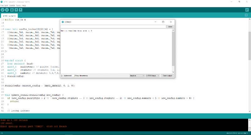
This week I tried to test Nicolas’s Protocol named Autobaud, it did not work because I did not have enough knowledge to dive in that deep in a week so I worked on I2C.
Nicolas made a nice Javascript interface to visualize the framing, addressing and encoding of his protocol.
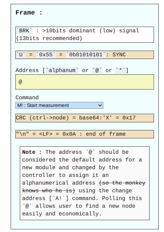
The ideas of Nicolas protocol are to use only 1 wire for communication, keep it human readable and be able to use existing hardware such as LIN is the auto industry.
To be honest Maxime and I did not completely understood in what use case it was better than existing solutions.
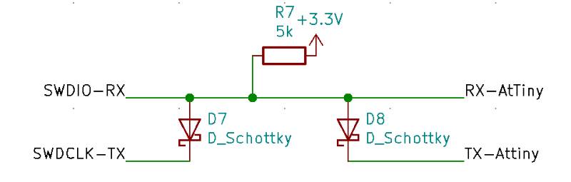
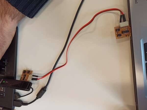
To test the connections using existing hardware, we connect the RX and TX together with a diod and we pull up RX. This way, when we write a LOW on TX the diod lets the current flow and then it is brought back up thanks to the pull up.
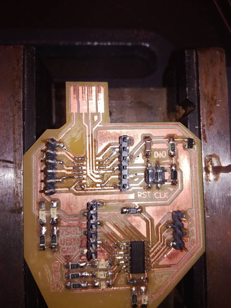
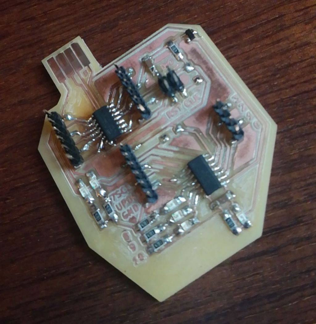
I designed a board including a SAMD11C14 and an ATTiny1614 to test the protocol on one single board and as you probably already guessed, the RX-TX pair that I used is the same as the SW programming pins so I had to desolder the diods to program the board.
I soldered everyithing and then had to desolder a couple of components because I could not load the bootloader until I understood the issue. Finally, I managed to load the bootloader but the board was still not detected by my computer…
Therefore I stayed stuck and did not find a way to get it detected.
I2C
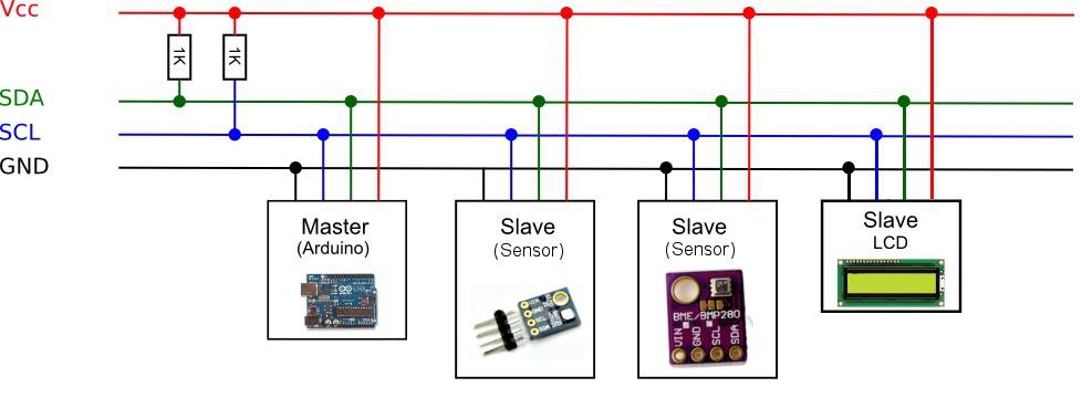
I2C (Inter-Integrated Circuit) is a protocol using 2 wires to communicate between circuit board (so low level). It is a type of Serial Communication Bus.
It uses two wires to communicate, a clock (named SCL) and a data (SDA) bus, both requiring a pull up.
In I2C, multiple devices are connected on the same bus and communicate together. There can be multiple Masters/controllers, and multiple slaves/peripherals.
The clock tells the host when to sample the data bus.
Different type of command can be sent, either to a specific peripheral or as a broadcast to each connected device.
When the message is sent to a specific device, the controller expects an Acknowledgment that the message has been well received. This is called ACK and is a simple pull down by the target device, if the message was not well received, the target does not pull down and the controller knows its message was not received properly.
To demonstrate I2C, I made an AtTiny412 board, my Micropython board and the SSD1306 OLED screen and blinked the LED on my AtTiny412 board at the same time as I was changing patterns on the OLED screen.
I then scanned the I2C bus to find the addresses of the different peripherals available on it in Python first.
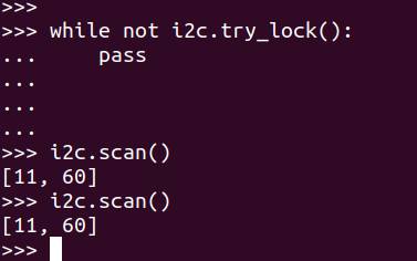
How does the scan work ?
The I2C scan is done by scanning all addresses over the 8 bit possibility which can thus be any number between 0 and 127.
For each adress, it starts a transmission to that address with Wire.beginTransmission(address) and ends the transmission with Wire.endTransmission().
As described in the documentation, Wire.endTransmission()‘s output provides information over the transmission
If the output is 0, it means that the device received an ACK and thus that there was a peripheral at that address.
Therefore, we record the addresses for which the output of Wire.endTransmission() is 0 and these are printed as the addresses of all the devices present in that network.
nDevices = 0;
for(address = 1; address < 127; address++ )
{
  // The i2c_scanner uses the return value of
  // the Write.endTransmisstion to see if
  // a device did acknowledge to the address.
  Wire.beginTransmission(address);
  error = Wire.endTransmission();

  if (error == 0)
  {
    Serial.print("I2C device found at address 0x");
    if (address<16)
      Serial.print("0");
    Serial.print(address,HEX);
    Serial.println("  !");

    nDevices++;
  }
  else if (error==4)
  {
    Serial.print("Unknown error at address 0x");
    if (address<16)
      Serial.print("0");
    Serial.println(address,HEX);
  }
}
if (nDevices == 0)
  Serial.println("No I2C devices found\n");
else
  Serial.println("done\n");

delay(5000);           // wait 5 seconds for next scan
I then tested it using the Arduino.
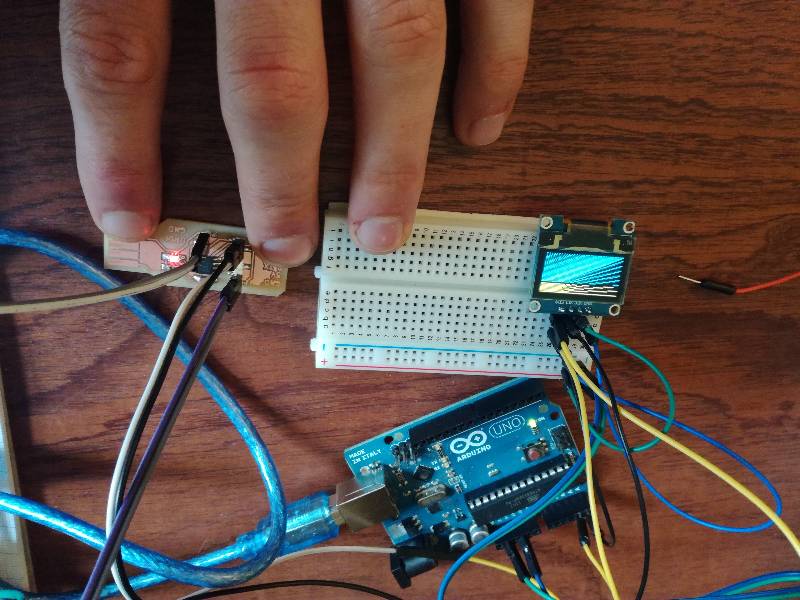
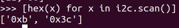
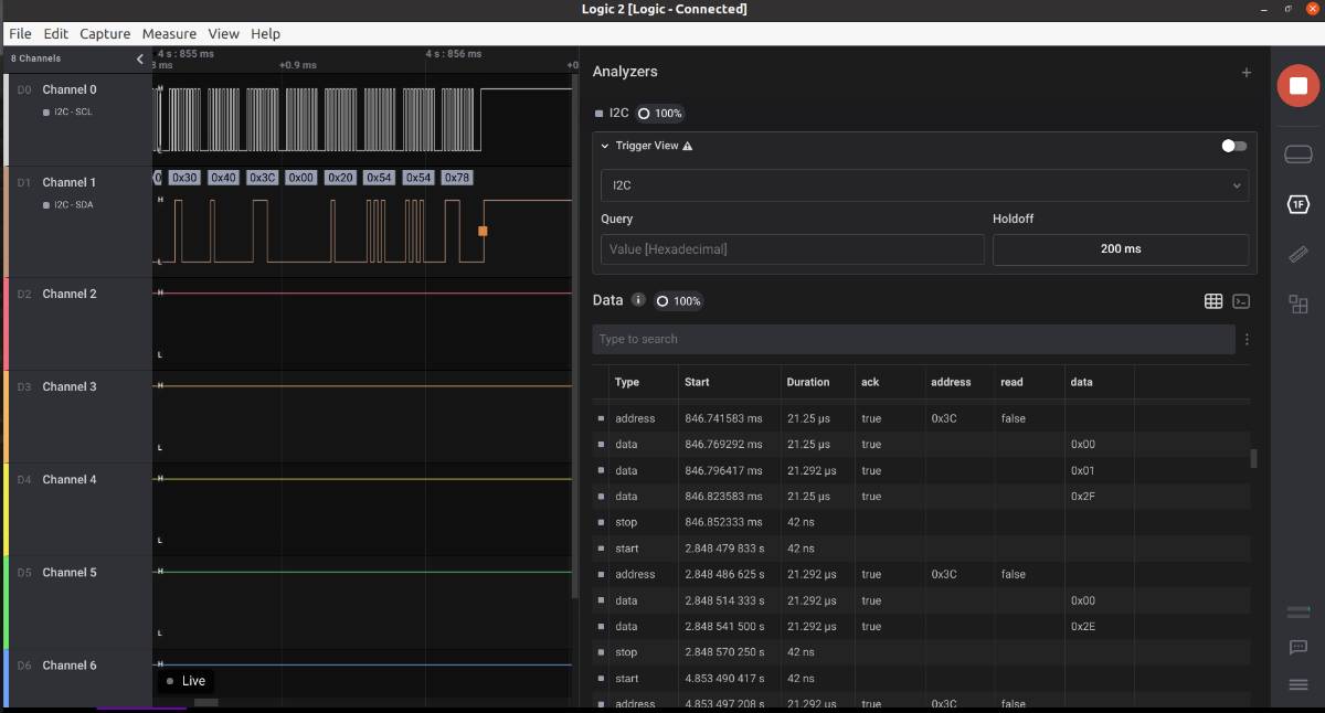
Also since I had just received my digital analyzer, I checked what I could read from the I2C bus and saw the data going to my OLED screen with the address Ox3C.
Group Assignment
During the Electronics production week, we tested UART communication between our boards with Maxime, through UART and also using the Micropython board.
With that and very simple code, we can communicate via our boards with each other.
void setup() {
   SerialUSB.begin(0);
   Serial2.begin(115200, SERIAL_8E2);
}

void loop() {
   if (SerialUSB.available()) {
      Serial2.write((char) SerialUSB.read());
   }
   if (Serial2.available()) {
      SerialUSB.write((char) Serial2.read());
   }
}
Doing that we had already tested communication without adresses.
We can make a serial bus by sending initial characters working as an address and filtering messages based on these initial characters.
However, I connected different projects with an I2C bus including an AtTiny board (tested above in another setup) and the board for my final project.
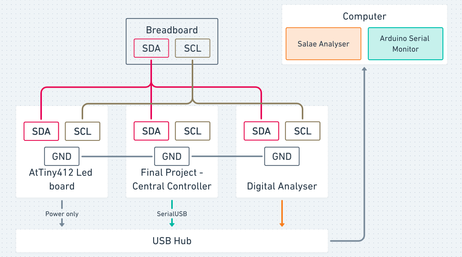
I also monitored the bus with a digital analyzer and while receiving messages from the SAMD21 board for my final project over the serial monitor.
The message makes the LED blink at different speeds and different number of times depending on the number sent. We can check this number by looking at the serial monitor as the samd21 board is asking the Attiny peripheral to send it or by checking the value sent on the bus looking at the digital analyser.
The code for this is available on the group page.
Files
- Arduino I2C Scan
- Networking AtTiny412 LED + OLED
- Host code AtTiny412
- Attiny Board
- Test Autobaud Board (SAMD11C14 + Attiny 1614)