8. Computer-Controlled Machining
- Study Plan
- Research / Group Assignment
- Individual Assignment
Assignment definition
Group assignment
Do your lab’s safety training : test runout, alignment, speeds, feeds, materials, and toolpaths for your machine
Individual assignment
Make (design+mill+assemble) something big (~meter-scale)
Group Assignment : Be Safe around the CNC
The group assignment is also detailed on the group page.
Understanding the milling bits
The first thing we did with to start working with the CNC is understanding the cutting tools and parameters.
First there is a big difference between drills and mills even if they look loosely the same. The difference is in what part of it cuts.
In a drilling bit, only the end cuts and the grooves and edges on the side are sharp but not cutting. They are there to evacuate the material.
In a milling bit, the cutting edges can be a bit everywhere depending on what you want to cut and how. Generally speaking, che cutting edges are on the side. Because milling bits are very different from one another.
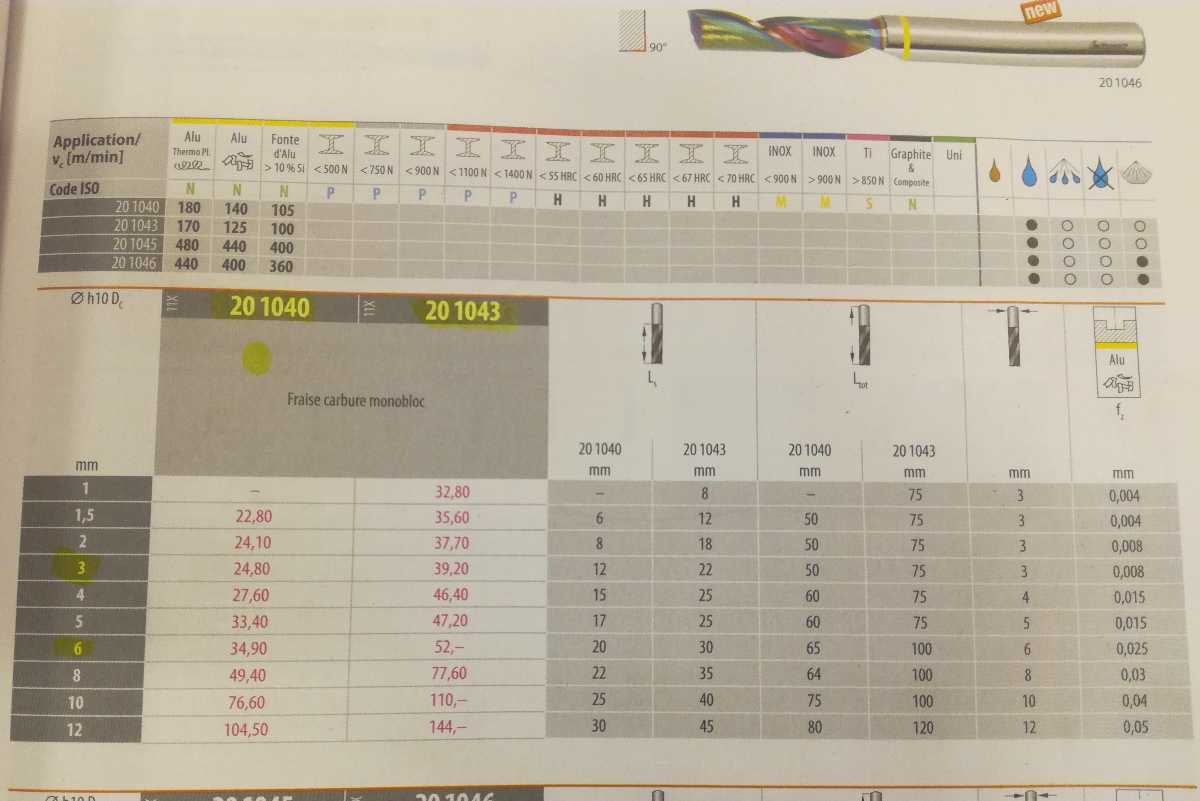
There are whole catalogues of milling bits and their characteristics.
Once you dive in the catalogue, you quickly realize it’s a good thing to have a guide because there are a lot of different bits.
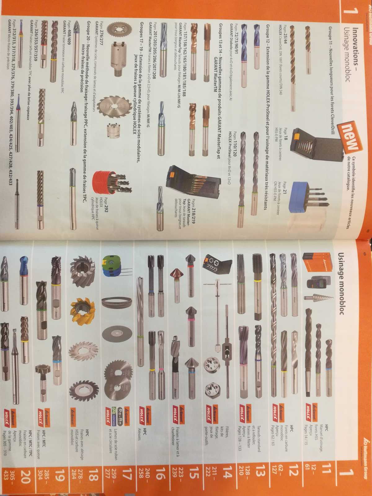
Fortunately, the pictograms and explanations in the book makes to understanding the parameters much easier.
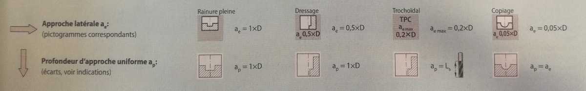
The important parameters are thus the following :
Cutting speed - Vc
This is the speed of the blade relative to the stock.
It is the product of the spindle rotational speed and the diameter of the bit. It is expressed in m / min.
Using this parameter and the diameter of the bit, we can define the spindle speed.
Advance per flute - Fz
This is the quantity of material that is chipped away by one single flute. In English, it’s named chip load but the French naming is much clearer in my opinion.
Using the advance per flute, the number of flutes of the milling bit and the spindle speed, we can compute the feed rate. which is the horizontal speed of the machine, which is expressed in mm / minute.
It varies a little if you are cutting through the stock or only on the contour, but as a general practice, using the lowest of the two is the safe option and does not change the overall duration of the work by much.
Cutting depth
Then there is the cutting depth which is the vertical dimension of the chip load. It answers the question : “How deep can I go in one pass ?”.
Our instructor gave us an acceptable rule of thumb for bits between diameter 3mm and 50mm, which is to never go higher than half the diameter, in wood at least.
This is apparently a bit more of an experimental parameter so you have to test it and check that everything goes well before increasing it.
Other parameters
Then there are lots of other parameters, starting with the shape of the bits, the angle of the flutes, the presence or absence of the central hole for chip evacuation, the end angle, …
A question that I still need to answer is what conditions the number of flutes. Apparently, some material “prefer” an odd or even number of flutes. It also greatly influence the chip evacuation.
Our milling bits
First, we checked our bits and discussed the errors of our peers.
The first lesson is a burned bit is a dead bit. Generally speaking, if our bits burn, they are no longer sharp and should be avoided.
A lot of our bits have been mistreated and are burned but we still have some acceptable, others have been ordered but have not arrived yet.
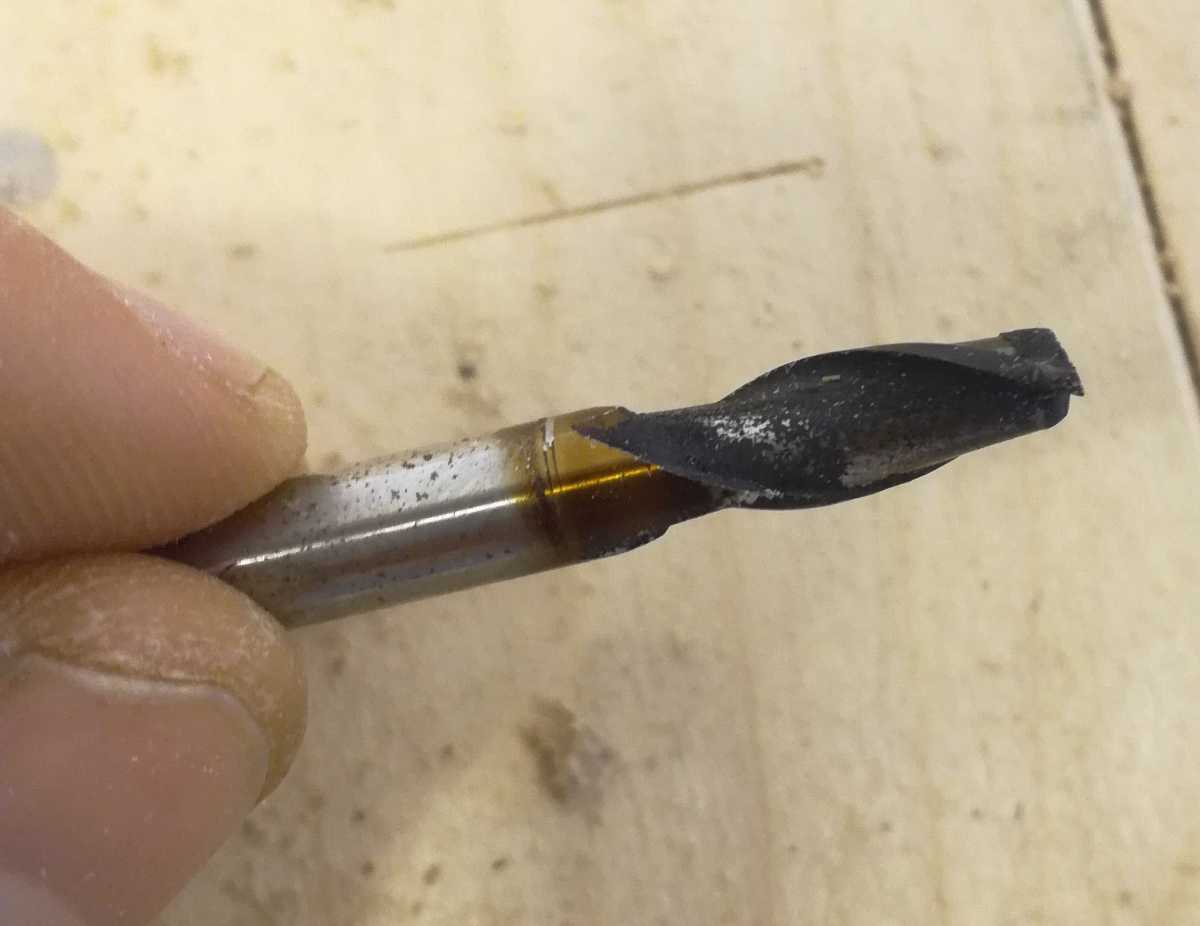
Some bits are only lightly burned and are still acceptable to continue.
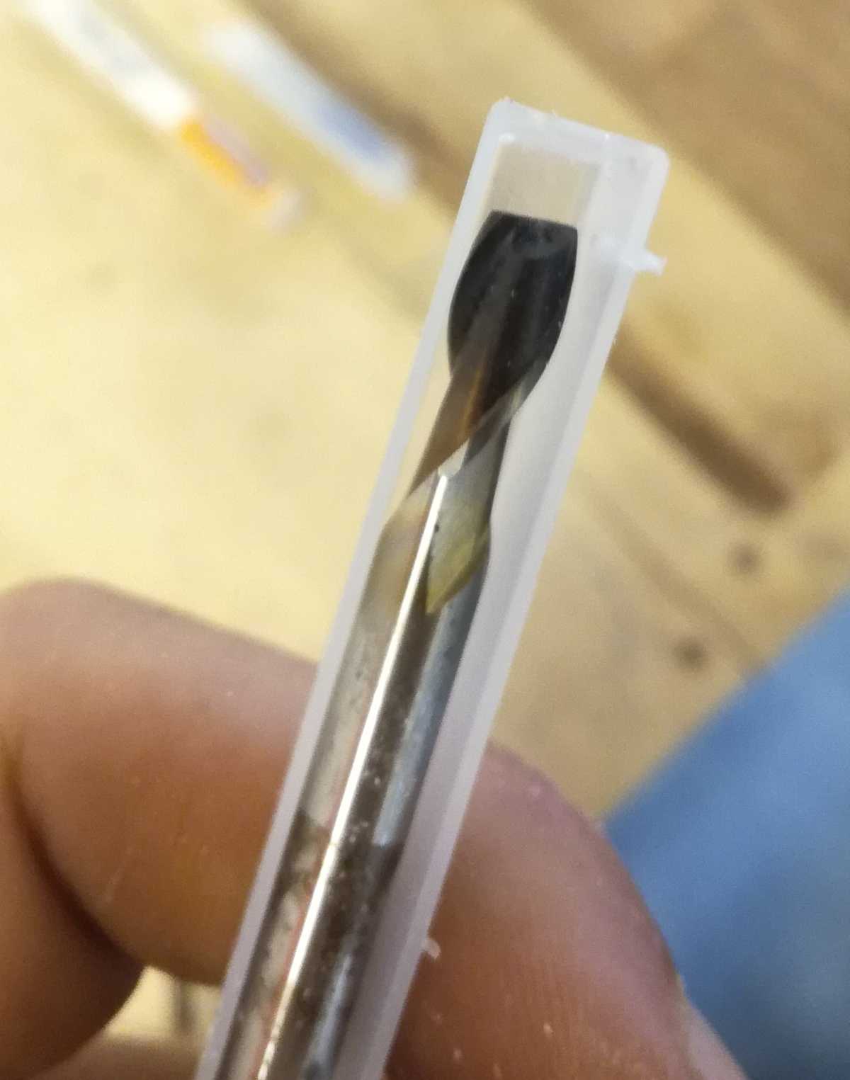
We used the single flute bit that was on the machine and we found it in the book so we have its characteristics. We can now move on to the machine.
Understanding the machines and the safety rules
We have a CNC-Step machine interfaced with kinetic-NC as software controller, and that is the post-processor we will need to export the CAM programming.
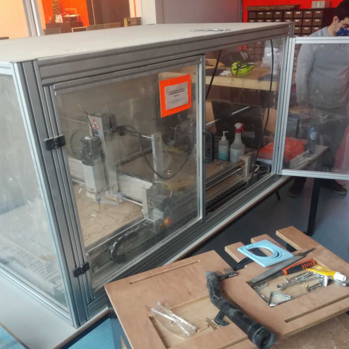
The machine’s dimensions are 120 cm x 60cm x 40 cm (XYZ) and has doors to keep the dust inside and mostly keep us safe from flying chips of the stock and from getting tangled in it.
Because of that it’s a little less dangerous. However it is still a powerful and dangerous machine so it’s better not to leave the room while it runs ! It’s also a machine that will potentially create a fire if not run properly.
Once the bit is safely attached and the doors closed, we can go behind the computer.
The interface of Kinetic-NC is quite practical and once you have the gcode for the machines it is quite easy to use.
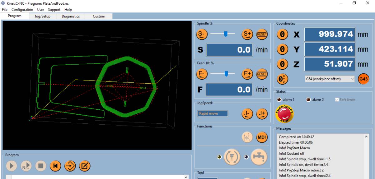
We set up the zero of the machine and make sure to select G54 as reference origin as this is by default the origin of the piece.
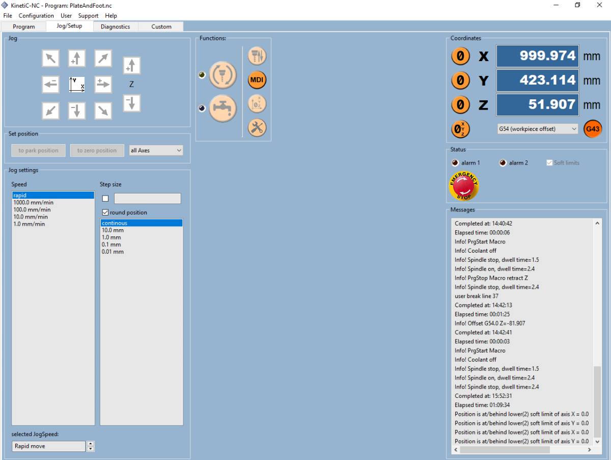
For the Z alignment, we have a script and a probe that makes it super easy.
We checked for a first test the CAM tools available with SolidWorks, specifically HSMWorks.
Individual Assignment : Make something big
Designing the table
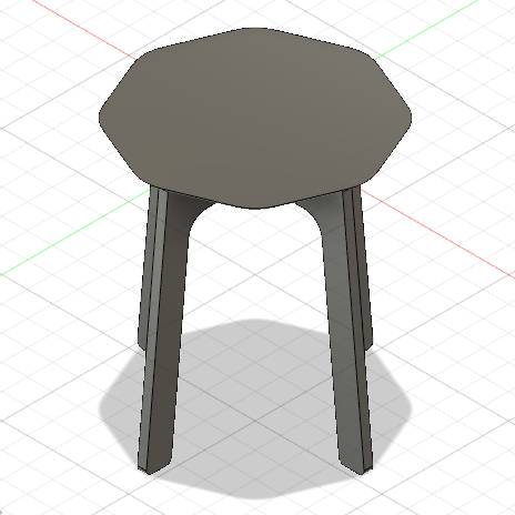
At first the design was a little different, much larger as a table should be but then I realised that the dimensions of the CNC were 60cm by 120 cm so my table was too wide. I thus reduced the dimensions to get a sort of stool.
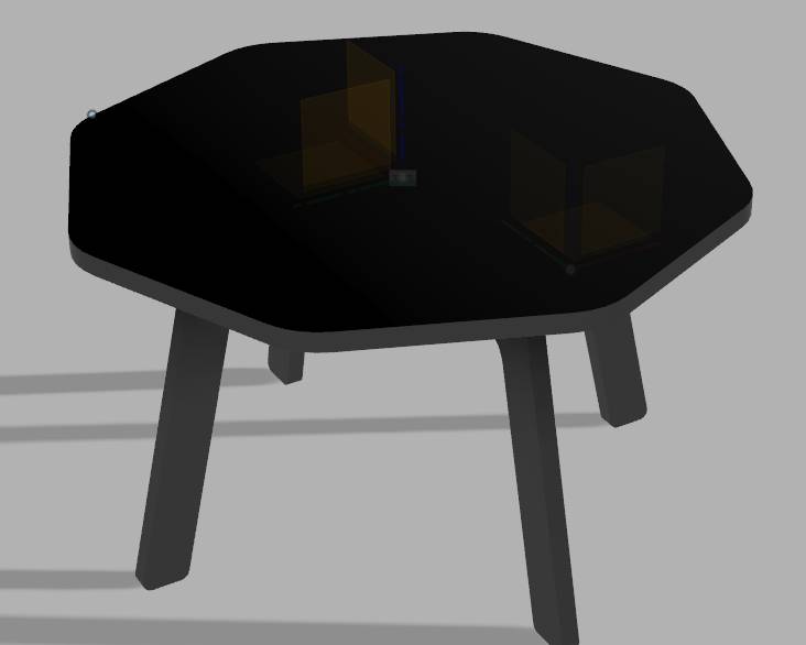
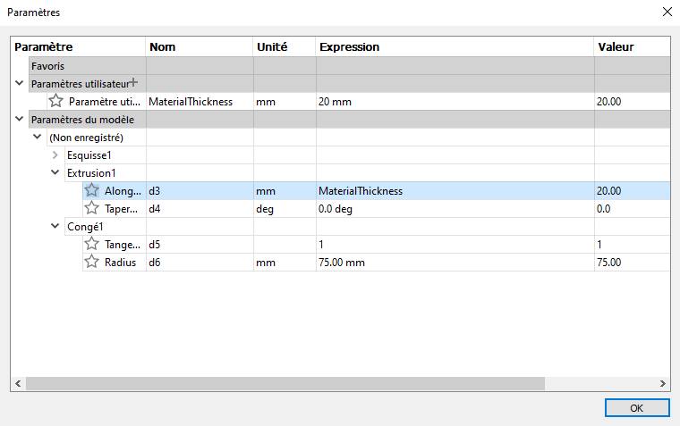
Off course from the beginning I had set up some parameters, so modifying it was not too difficult.
I ended up with a sort of nightstand / stool.
Learning CAM
I first tried to stay on Onshape solution as it is the CAM system I like best, for the main reasons that I can run it on Ubuntu (it runs in a browser) and is super user-friendly. I found Kirimoto as an add-on app to do CAM but it did not load so I moved to Fusion360 on a Windows computer.
The “Fabrication” tab in Fusion360 is quite intuitive. As I had seen how to do it in SolidWorks, I knew what I had to do, I just had to figure out how to do it.
The different steps to follow are:
- Set up the stock (Configuration)
- Create the tool library
- Define the manufacturing passes
1. Configuration
Defining the stock looked easy but directly when I saw that it defined the stock based on the assembly. This is not what I wanted to do, as I planned to use planks of wood.
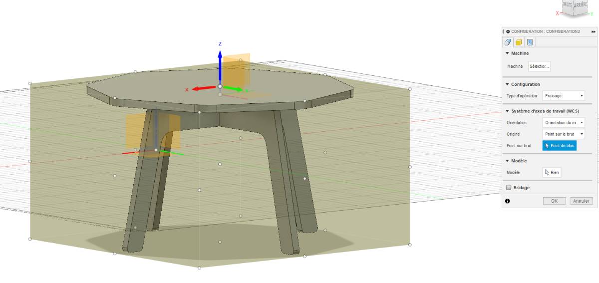
Asking around and checking on internet how to lay the elements flat, I saw it had to be done manually so I did in a new file, which made creating the configuration easier.
The important thing is to make sure the thickness of the material on top, below and on the sides is appropriate and fit the plank that you are using. Because of the dimensions of the machine, I divided the work in two parts.
Tool library
Before defining manufacturing commands, we must define our tool library. Because we checked the tools catalogue first, it is very easy to do.
A lot of parameters won’t actually be used so we can skip some of them.
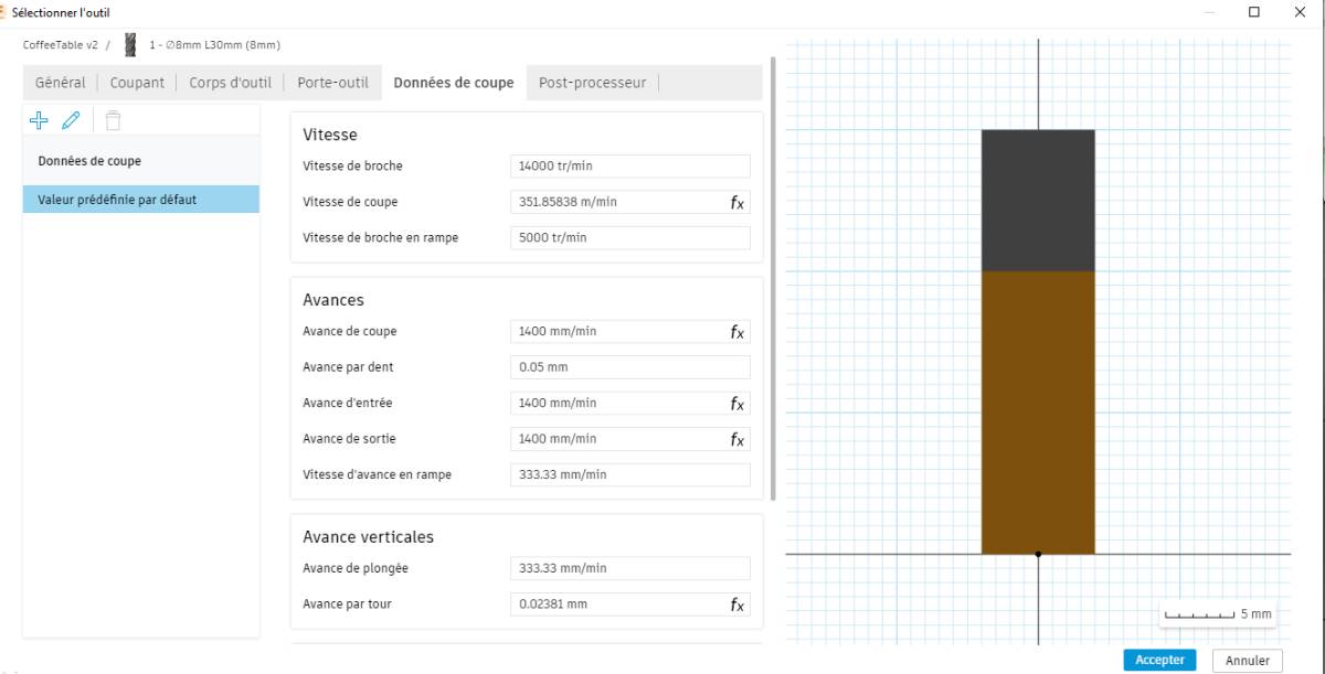
Here we see directly the link between the parameters such as the cutting speed and the spindle speed.
We add them to our custom tool library and move on to the next steps.
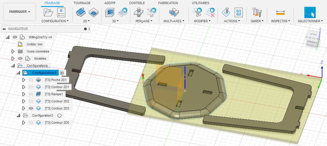
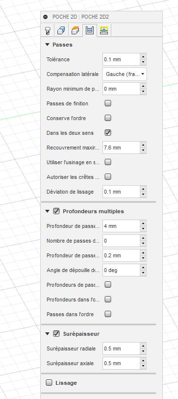
Define the manufacturing passes
When creating a manufacturing command, we first select the tool.
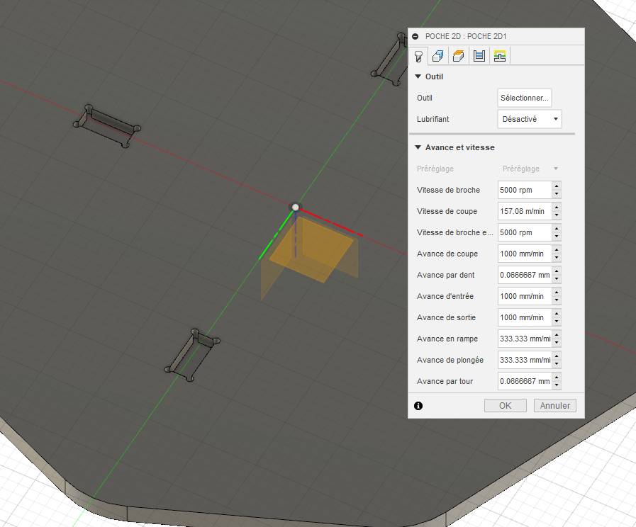
The parameters of the tool can be set up in the tool library and changed for a specific command in the command line.
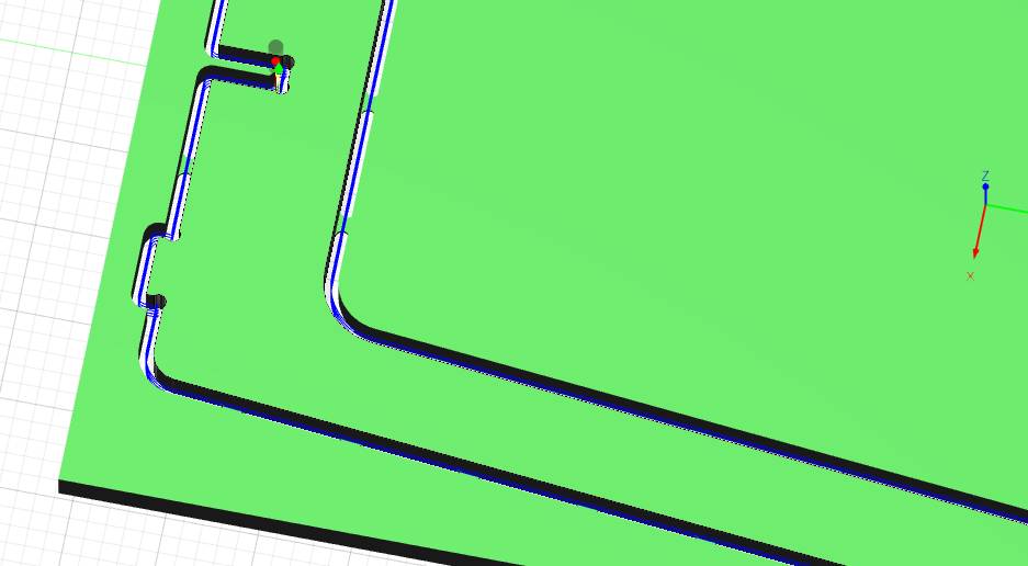
After that, we specify the parameters of the pass, the number of passes, their depths, the strategies, …
Making the table
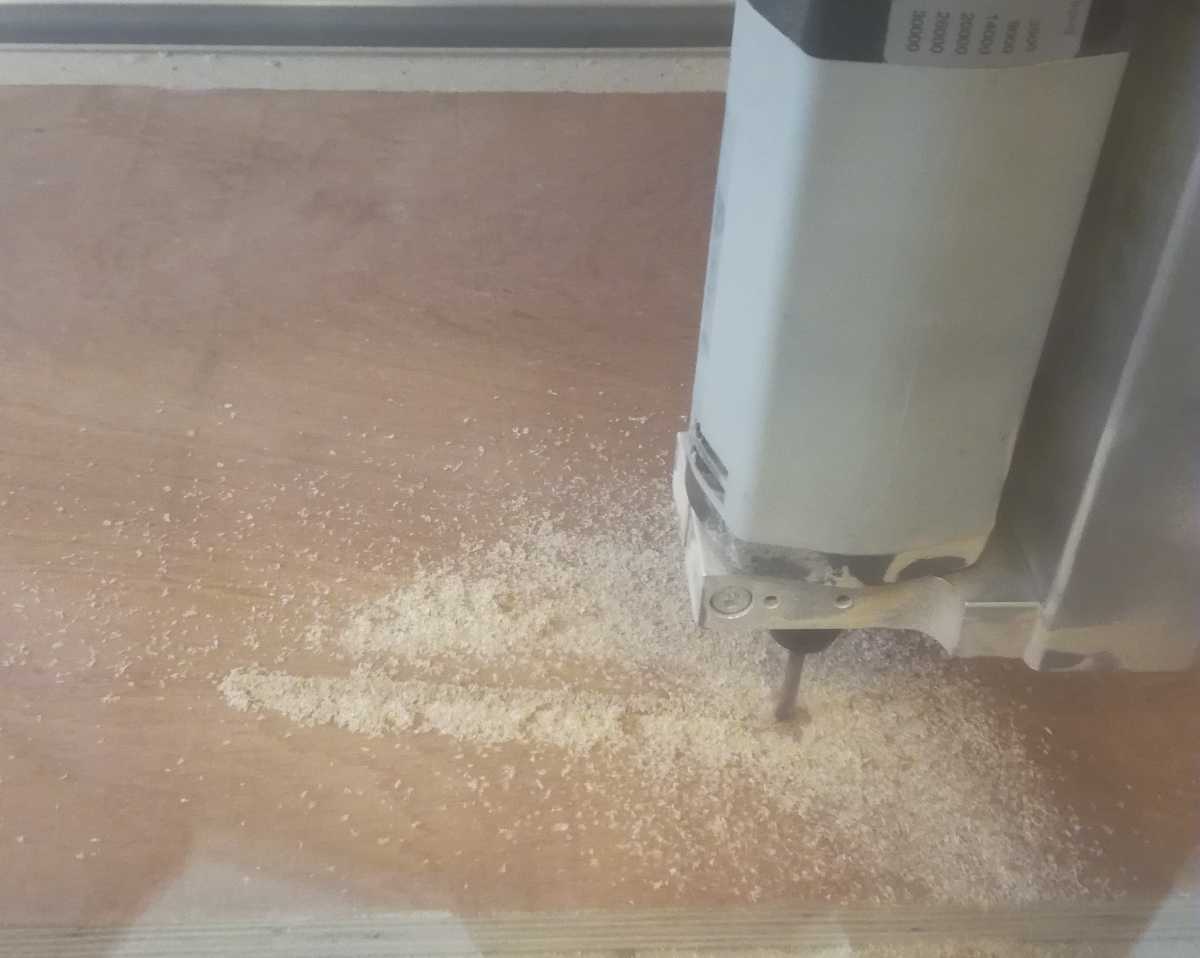
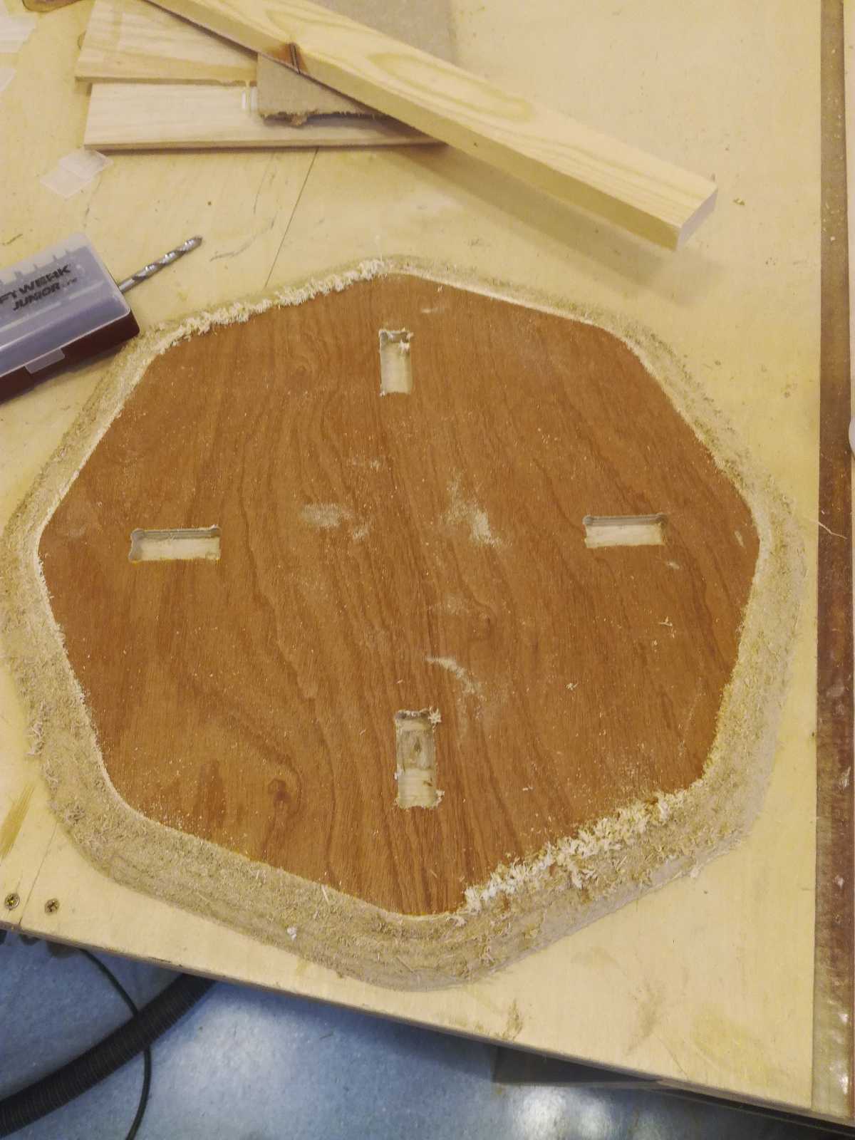
To fix the stock to the CNC, I drilled holes in the corners and screwed it in the spoilboard.
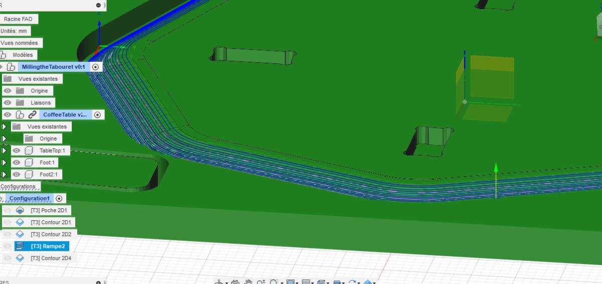
Once that was done, I started by the first leg of my table. Following the advice of Christophe, our instructor this week, I started with a feed rate of 30% of the programmed one to make sure I was not
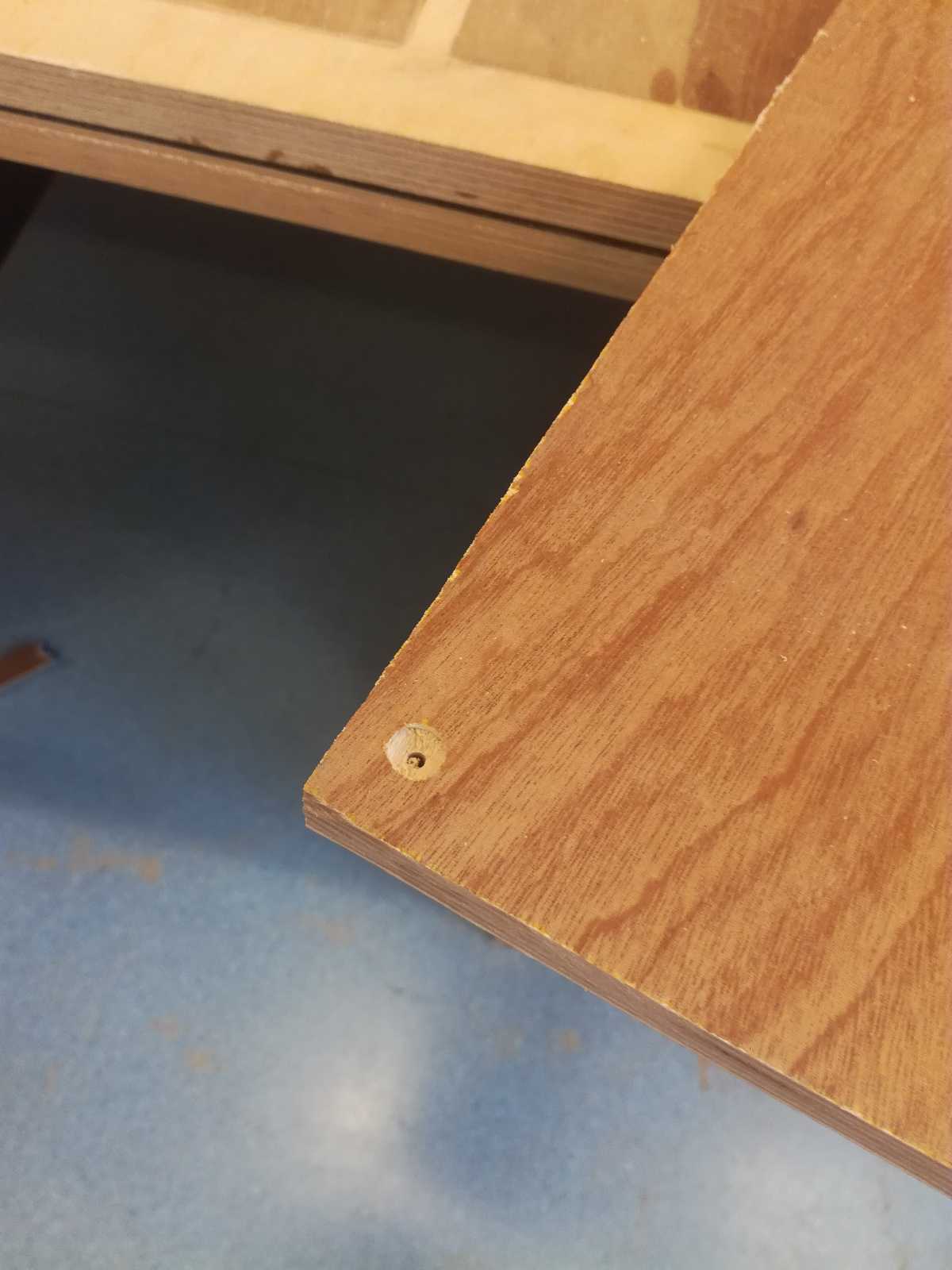
Once the milling was complete, I saw a problem.
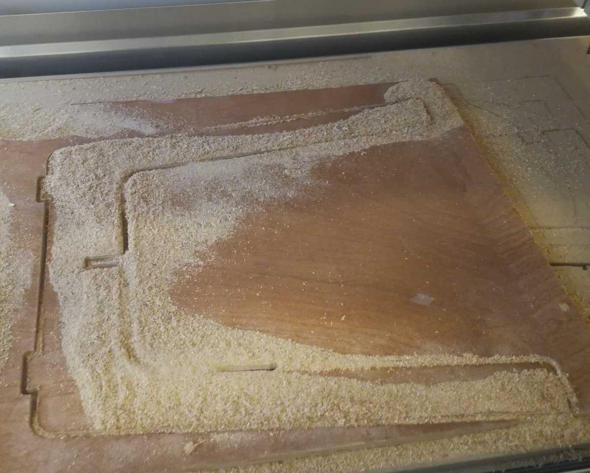
The spoil board is not flat because so many students used it inappropriately that they destroyed the spoil board.
Fixing my plank to it made the plank not perfectly horizontal and the CNC failed to cut it through on the whole periphery.
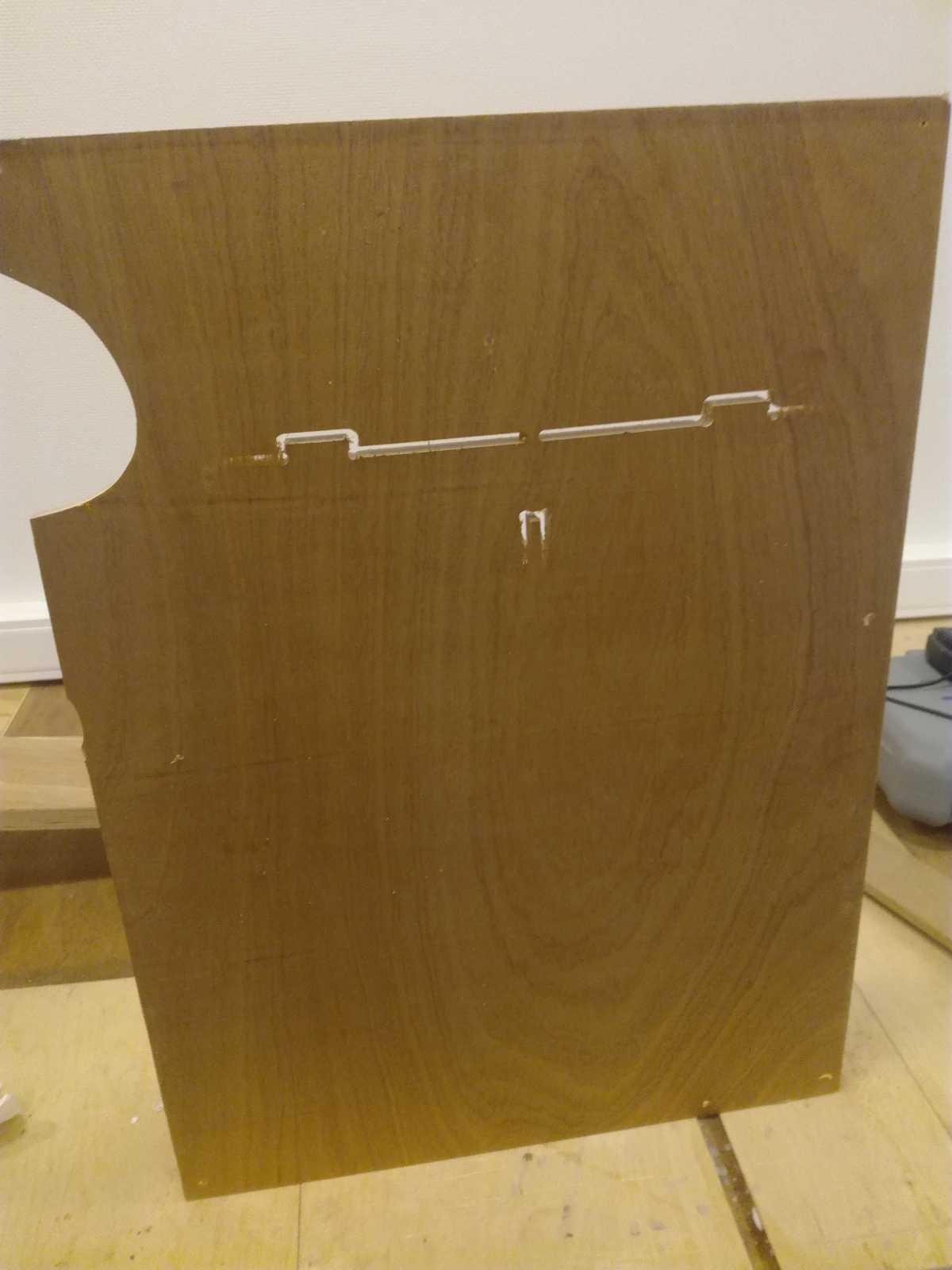
For the second half, the situation was not as problematic because no corners nor fixations were in a hole of the spoilboard.
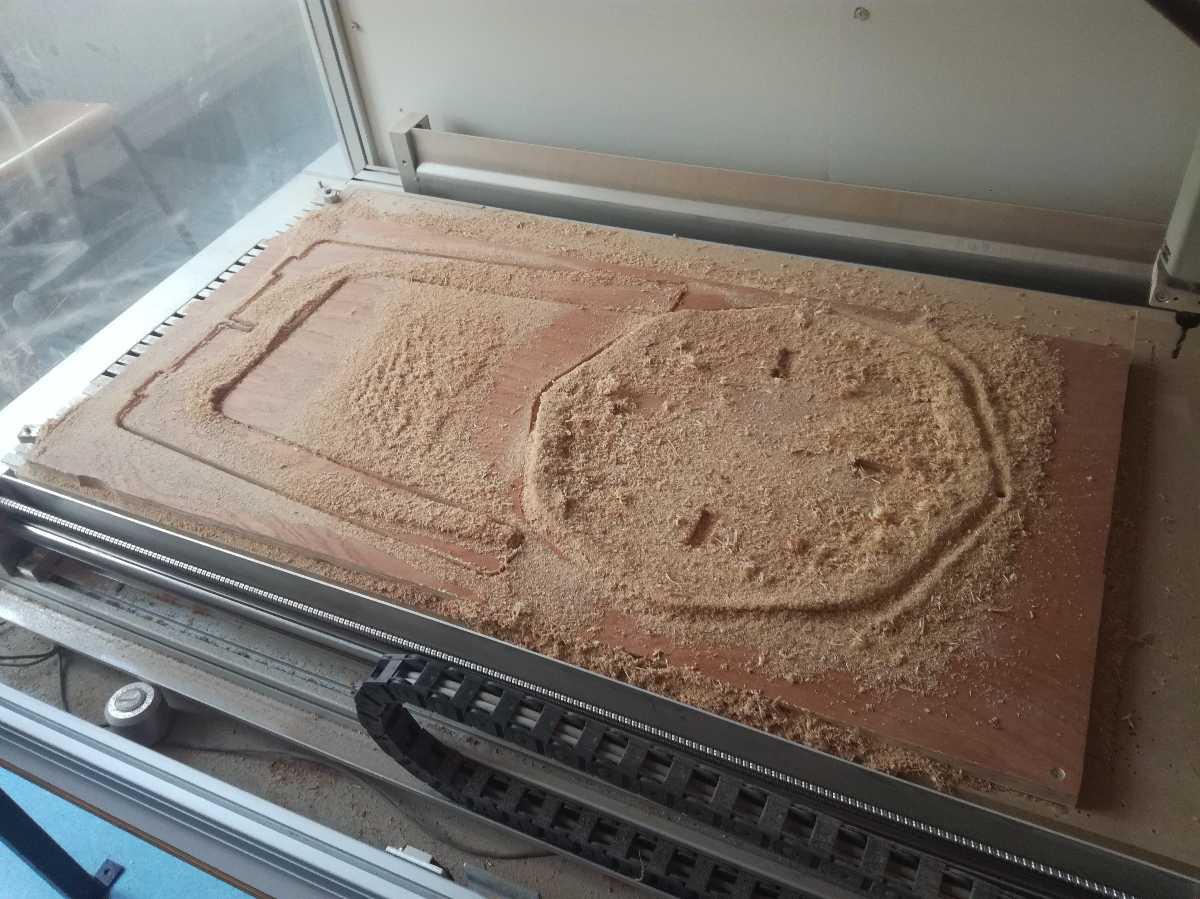
In this case however, the ramp that I used to cut the edge of the table left a lot of material to be removed.
Therefore, I used a electric sanding machine and in 5 minutes it was done.
I checked at the fablab that it was assembling correctly and took the stool with me.
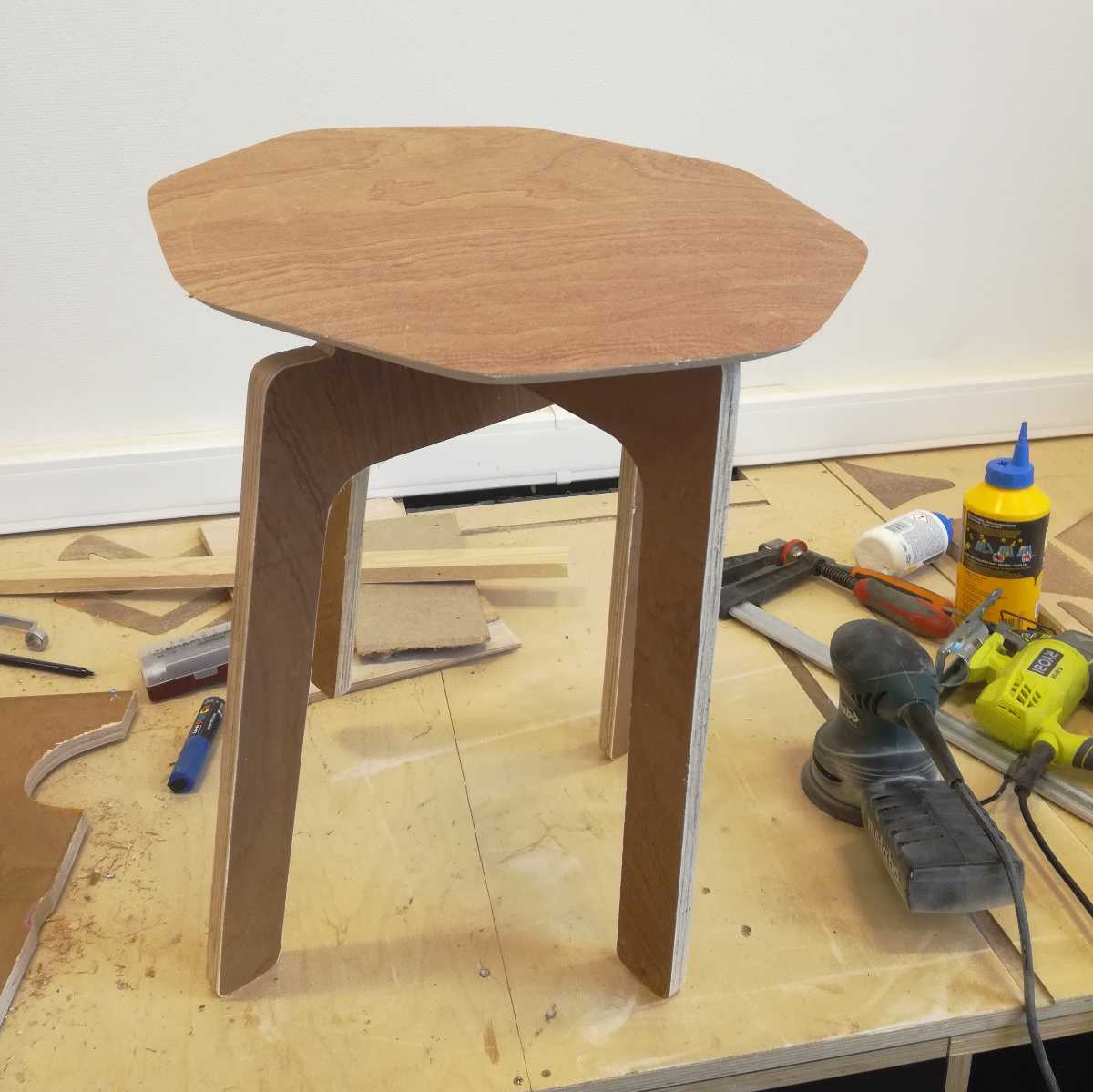
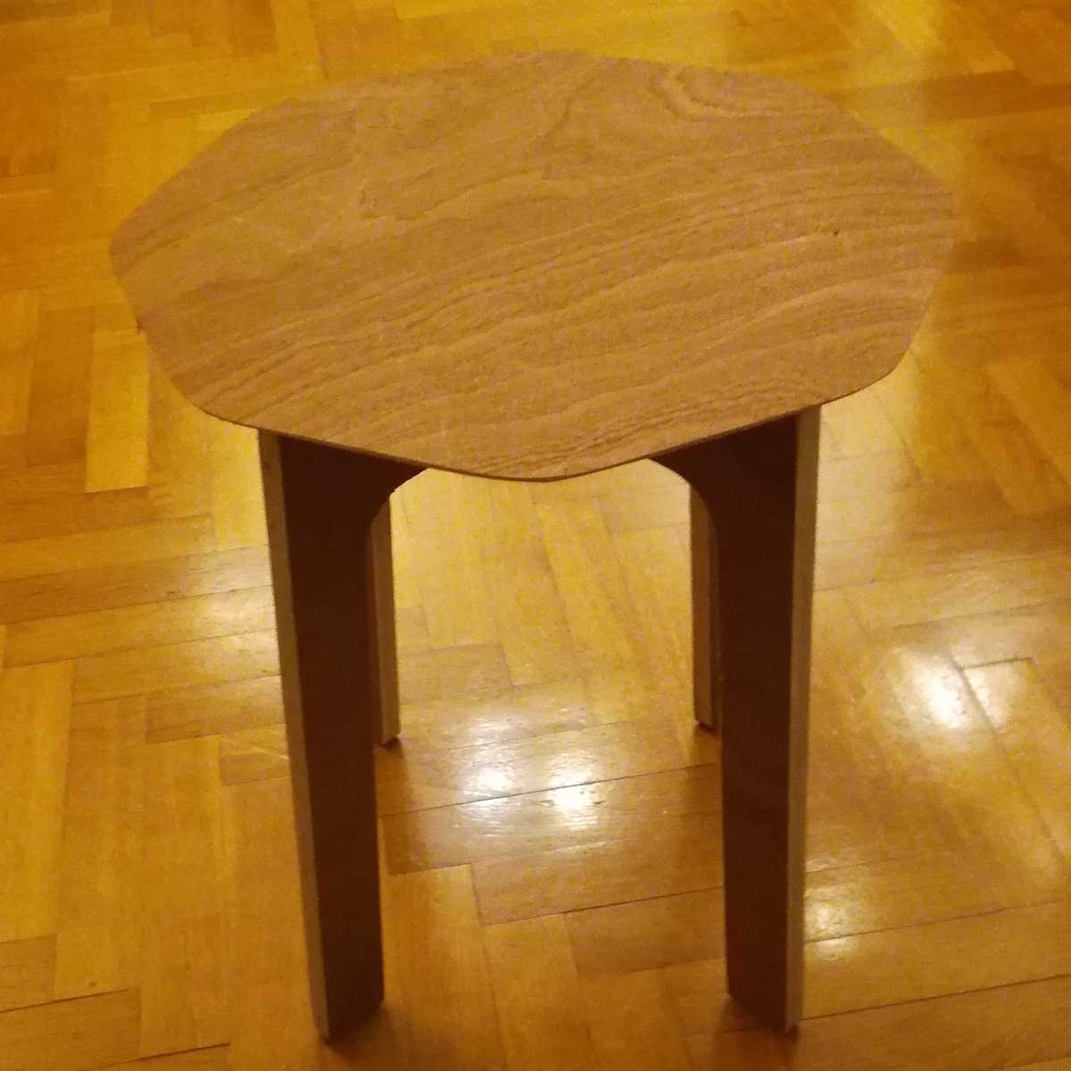
Travelling with it was super easy as I was riding my bike and it fitted perfectly in the bicycle fonts. I then assembled it and the press fit worked directly ! How lucky I was, I had not made sufficient test to verify it first !
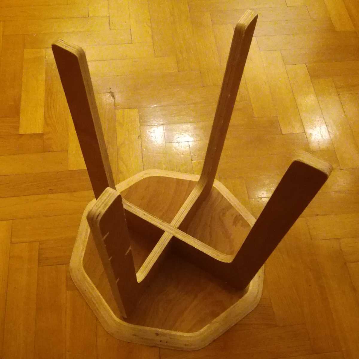
The chair is in its new home and I have now two orders from a friend and my mother for another piece of furniture !
Files
- Fusion360 files
- Gcode for the first leg using a stock of 0.6m X 0.6m X 18mm for KinetiC-NC
- Gcode for the plate and second leg using a stock of (1m X 60mm x 18mm) for KinetiC-NC