5. Electronics Production
Learnings from last week
I felt much more organized and productive. I still want to improve
- Study Plan
- Research / Group Assignment
- Individual Assignment
Study Plan
| Day | Activity |
|---|---|
| Wednesday | Course with Neil Gershenfeld |
| Thursday | Introduction to Bantam at FabLab |
| Friday | Document Group Assignment, Introduction to Voltera & Programming circuit |
| Saturday | Design Final Project, Document & Global Open Time |
| Sunday | Break |
| Monday | Mill, solder program JTAG programmer |
| Tuesday | Complete documentation |
Assignment definition
Group assignment
Characterize the design rules for your PCB production process: document feeds, speeds, plunge rate, depth of cut (traces and outline) and tooling. document your work (in a group or individually)
Check the PCB quality
Individual assignment
Make an in-circuit programmer by milling and stuffing the PCB, test it, then optionally try other PCB fabrication process.
Group Assignment
We documented our group assignment here. We started by using Gerber files.
After that we did it individually using PNG and mods to create the gcode.
Individual Assignment
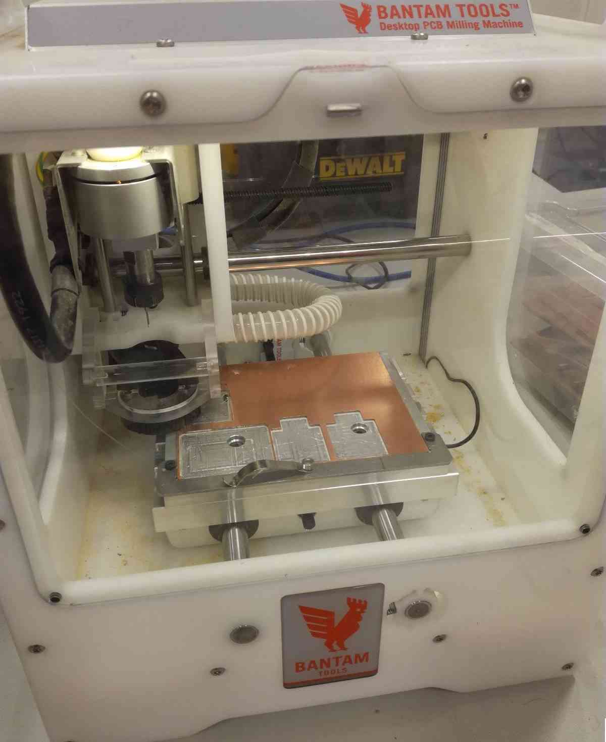
Milling
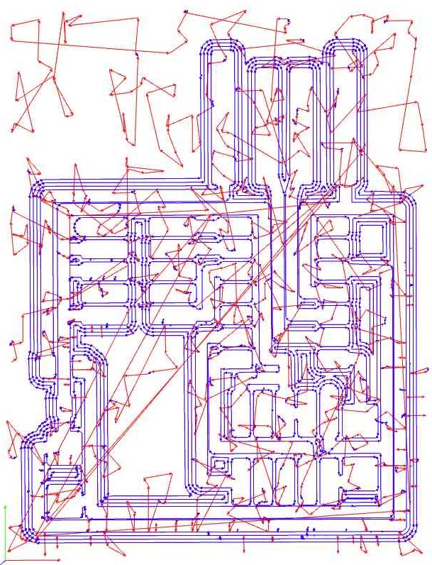
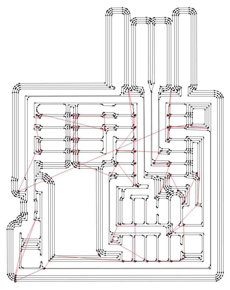
I started by milling my circuit using the gerber files for the SAMD11C14 UART/UPDI programmer from Quentin’s website
|
Starting with an already used board | |
| Changing the tools | 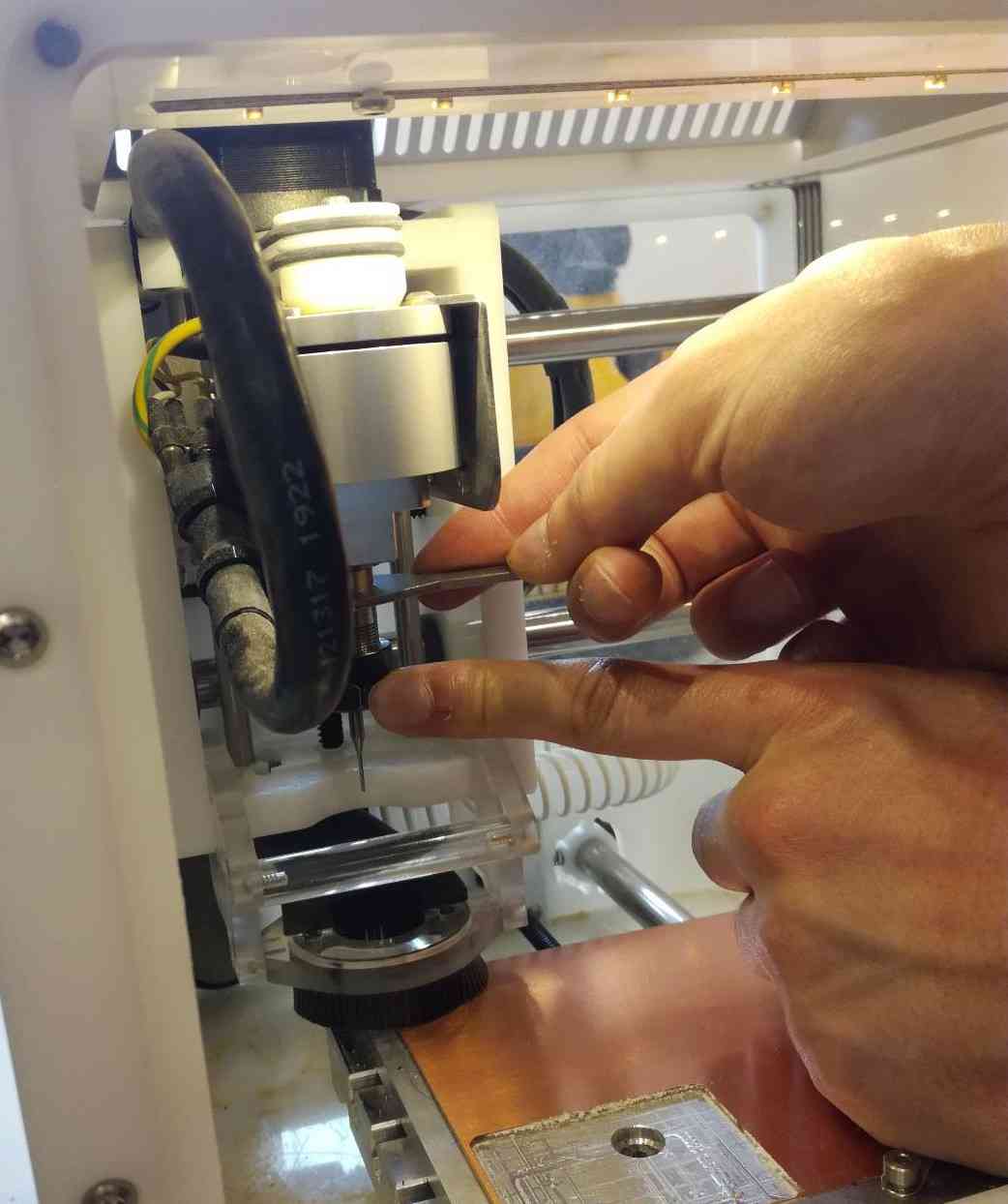
|
|
|
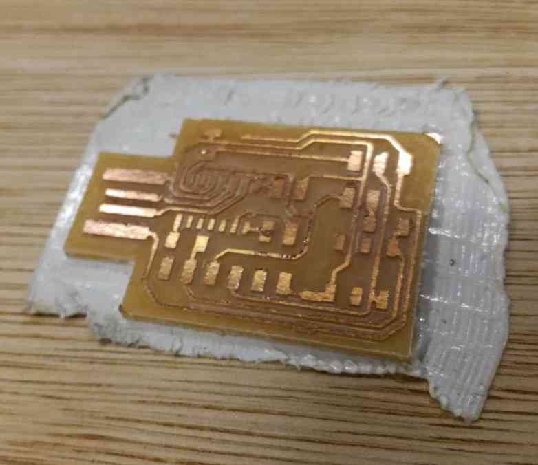
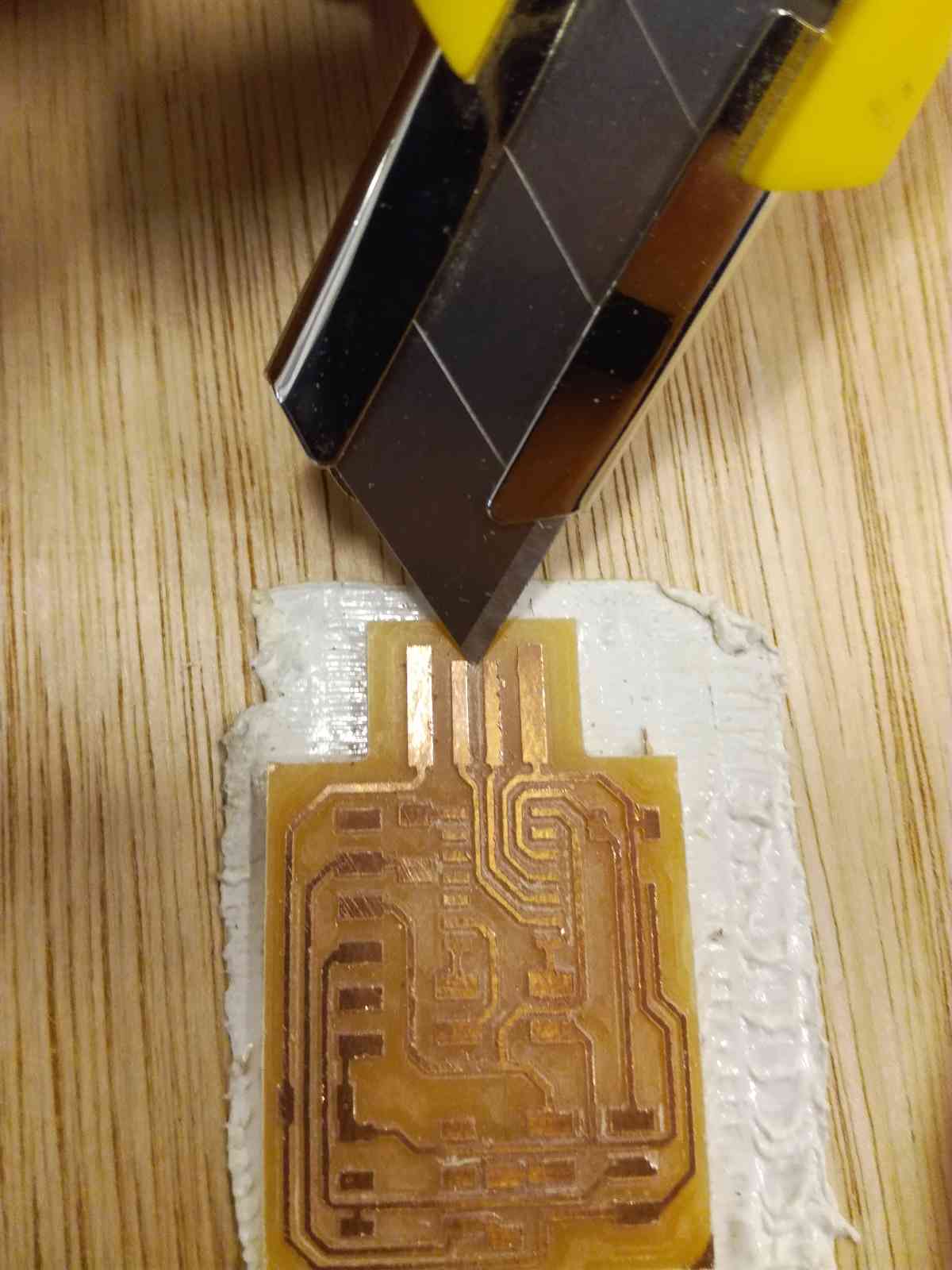
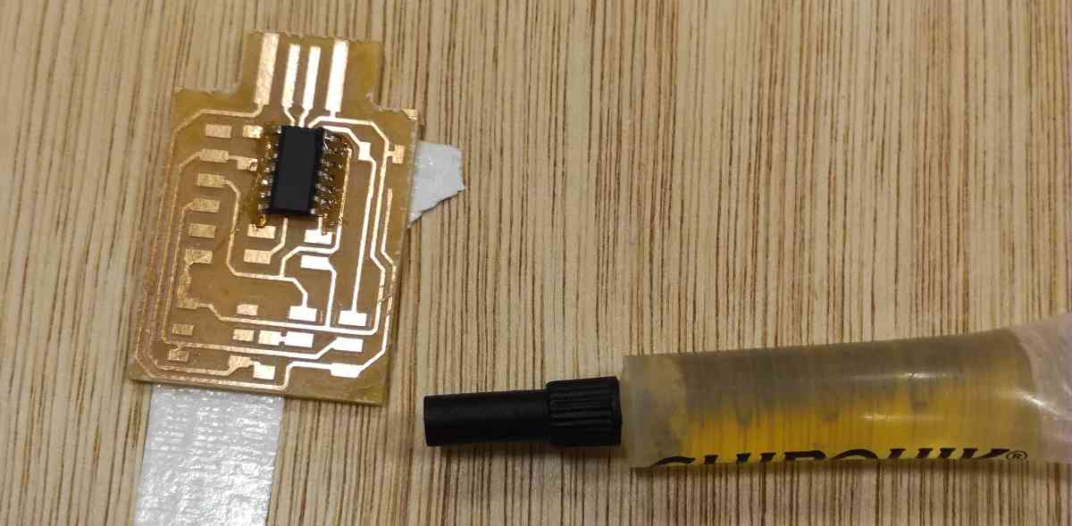
The clean board ready to be soldered |
After milling the board, some milling burr stay on the border on the copper so I sanded them and removed the excess copper with a cutter.
Components
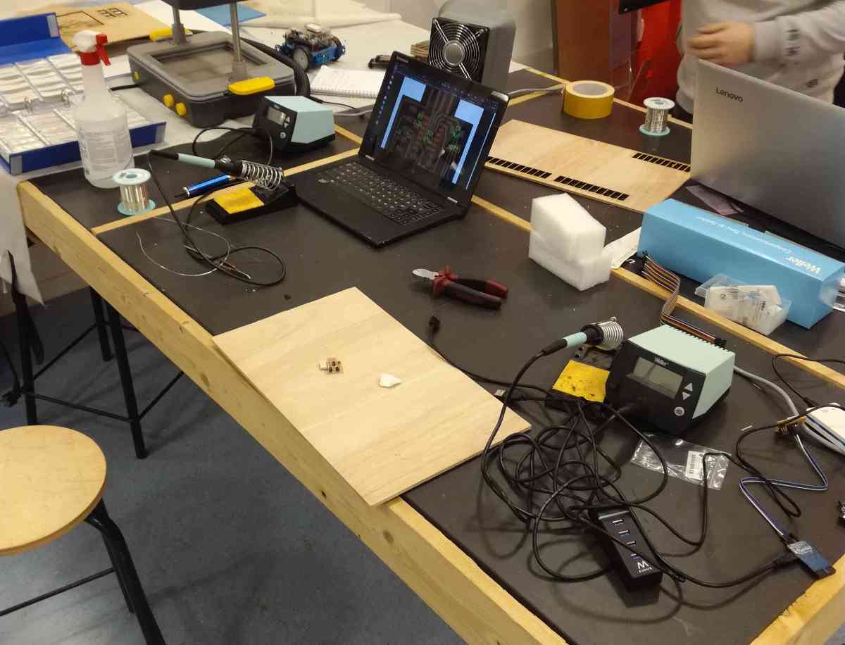
We prepared all the material to solder in good conditions:
- Soldering iron
- Soldering pump
- Soldering wire
- Clean wooden board to attach our circuit to
- Cutting pliers
- Sponge and soldering iron holder
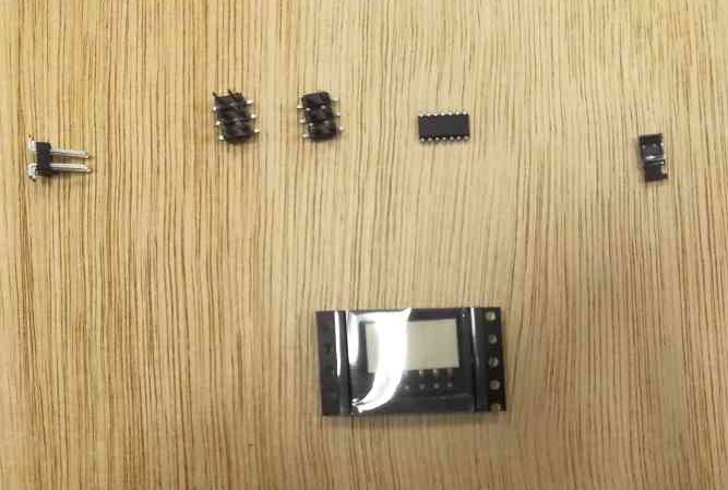
I prepared the material for my circuit.
|
I prepared most of the components before starting. | |
| The resistance are kept in a folder with all values in order. | 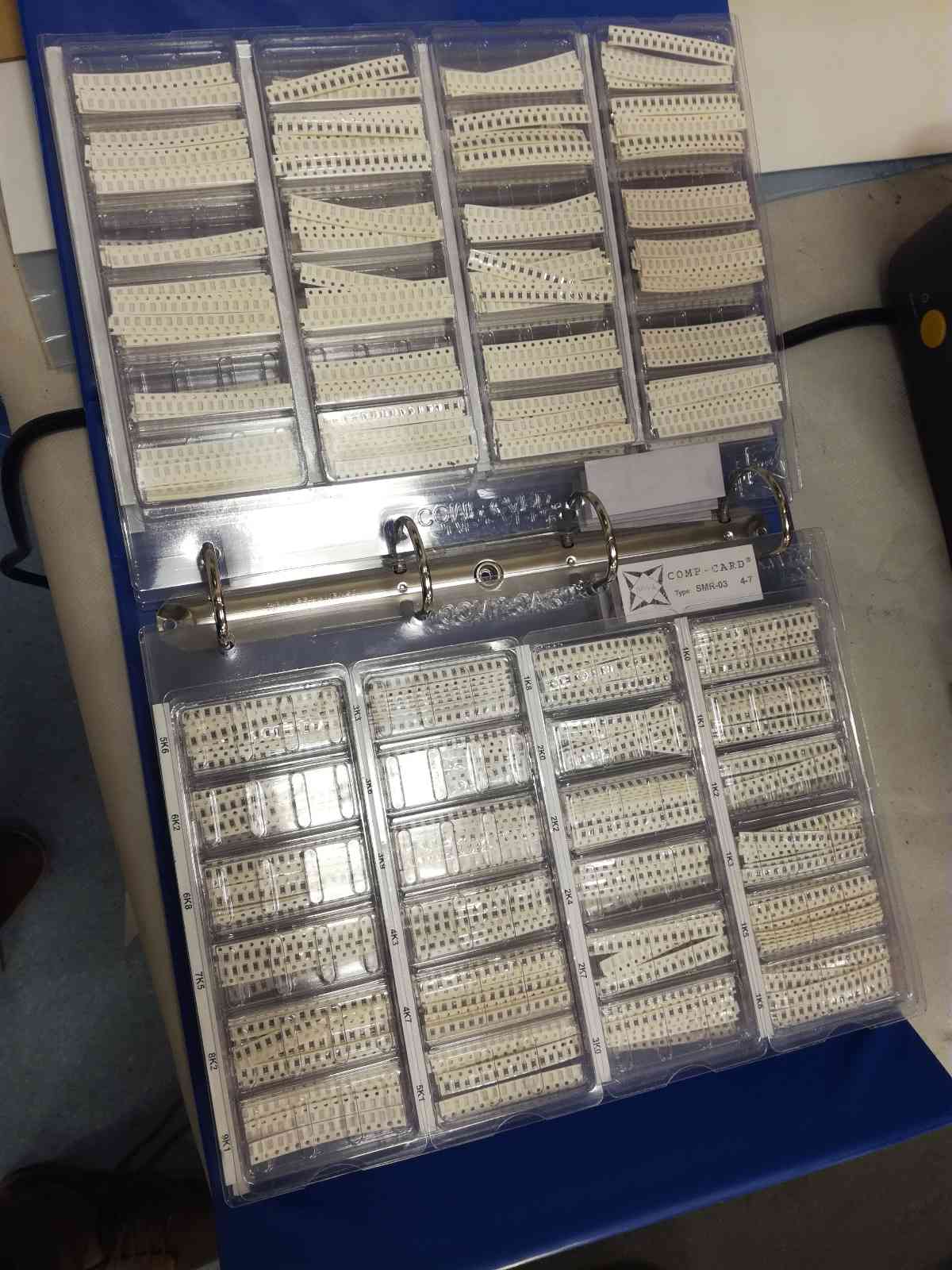
|
|
|
Keep a look at the files to check the orientation of the components. |
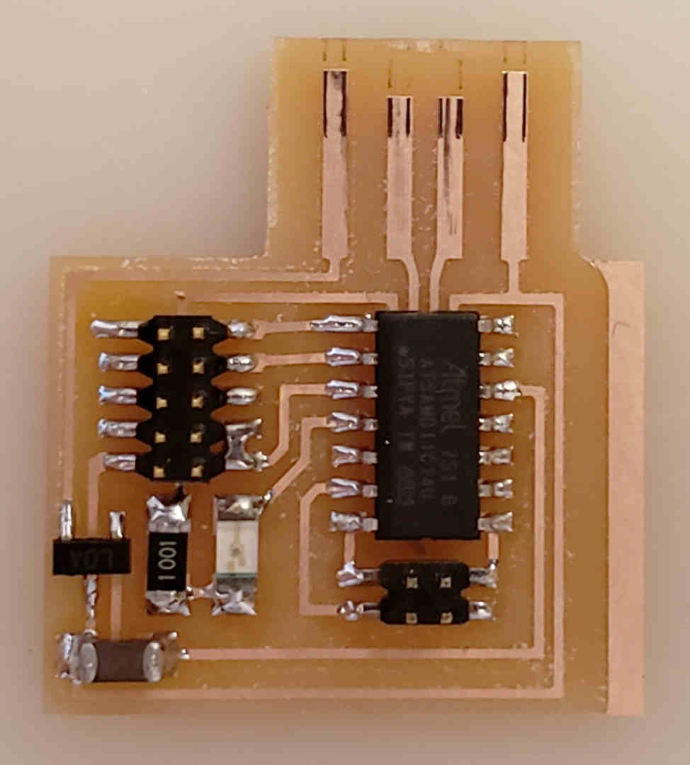
Pay attention when soldering the microcontroller to put in the right orientation, the dot must go where the pin name starts with a “1” or where the dot is on the schematic.
If you make a mistake there you can start over because the whole thing won’t work !
Soldering
I had already soldered a little but never SMD (Surface Mounted Device) components.
I did my best to solder them and was quite succesful ! Nicolas De Coster showed me how to solder with flux and it makes life it much easier.
How to solder
- Put some solder on the iron
- Heat the copper so that some solder is transferred
- When the copper is hot, the solder can flow on the surface because it will remain liquid due to the high temperature.
- Add a little solder to make a good connection
- Wait for the solder to flow between the legs of the component and the board.
The problem that may arise as was my case, is that some solder may be stuck between two copper pads. In that case, you have to remove it to prevent the short circuit. but that can be very difficult, especially when soldering a microcontroller for example.
That is a good occasion to use flux.
How to solder with flux
- Apply the flux on all the legs you want to solder
- Put some solder on the iron
- Pass the iron on the legs in a continuous movement to apply the solder on each
- Continuously add some solder to the iron to ensure the connections are properly done
If you have applied too much solder and some legs are connected together, you can go back with the soldering iron and distribute the applied solder between all the legs. This is when the flux gives all his power, because it goes between the copper pads, it prevents the solder from going there and facilitate the creation of a clean separated solder without short circuit.
|
Applying the flux | |
| The legs are well covered | 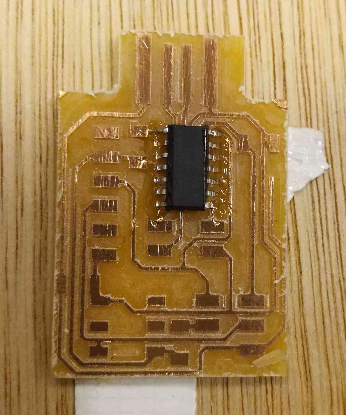
|
|
|
The solder was well applied only on the legs. |
I did my first board well but I took away some of the copper of the connectors and decided to make another one.
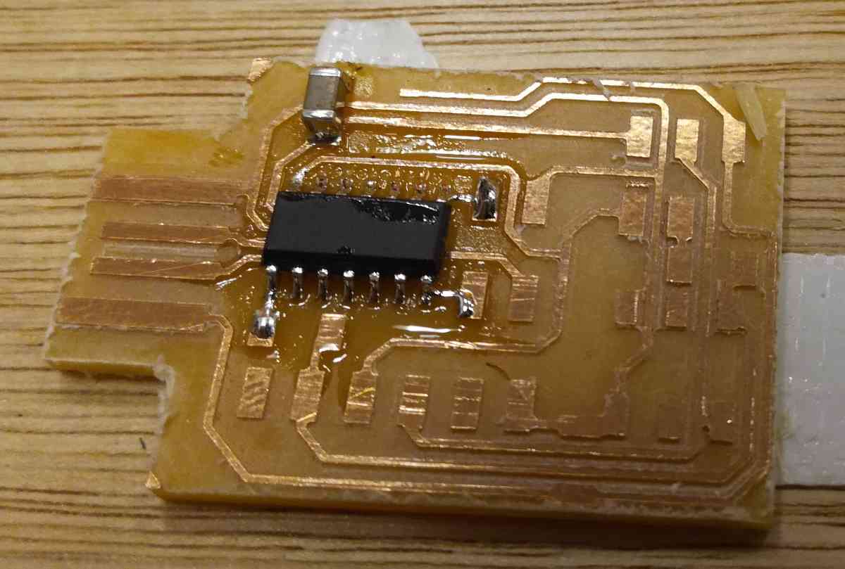
Fast forward, I redid it and it’s nearly finished !
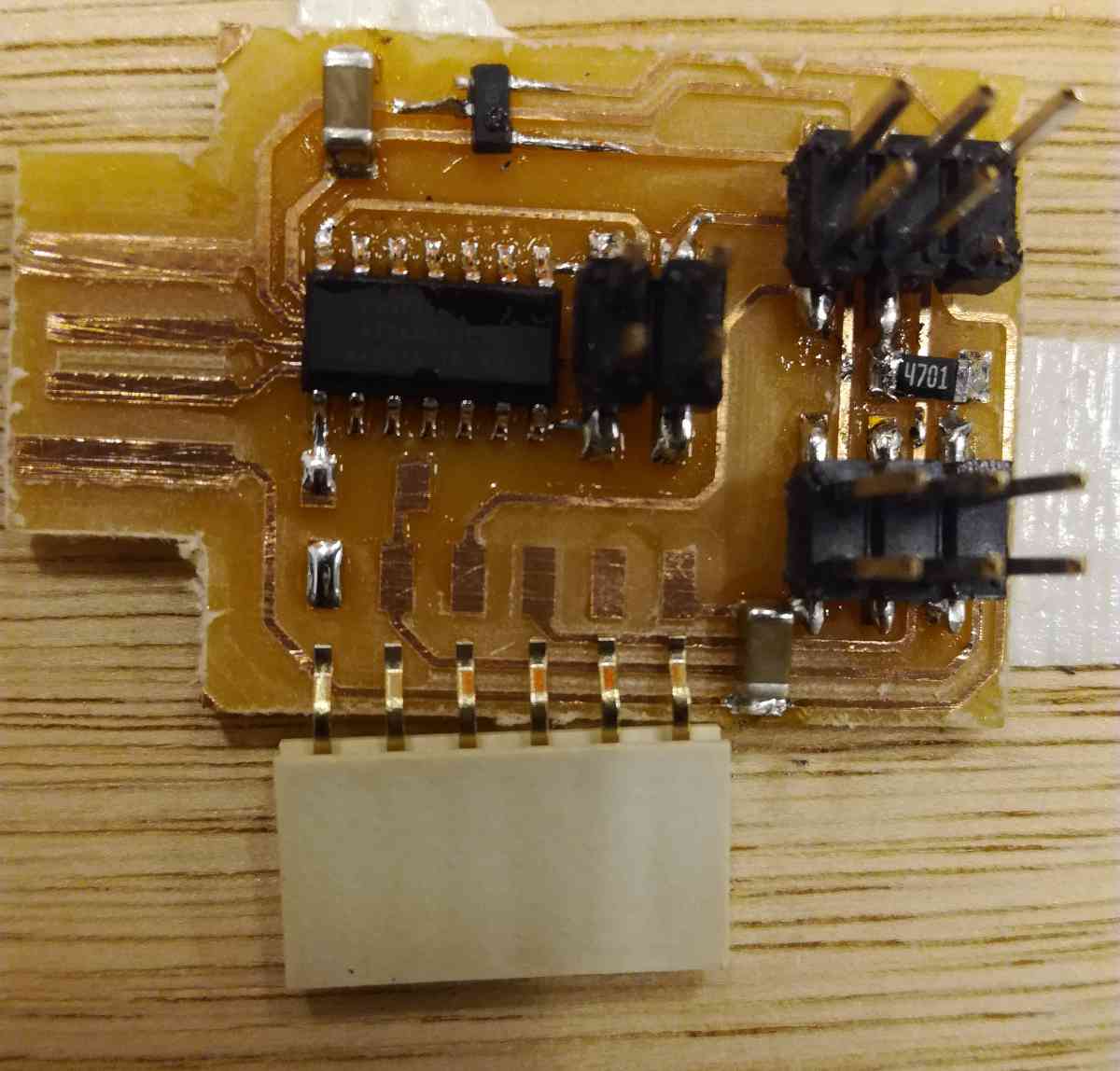
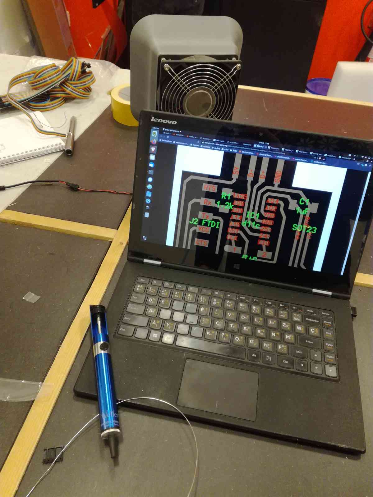
Doing that, I kept my computer open to check on the circuit and the components to place.
Programming : Flashing the bootloader
Before starting, I downloaded edbg and the binary file sam_ba_Generic_D11C14A_SAMD11C14A.bin
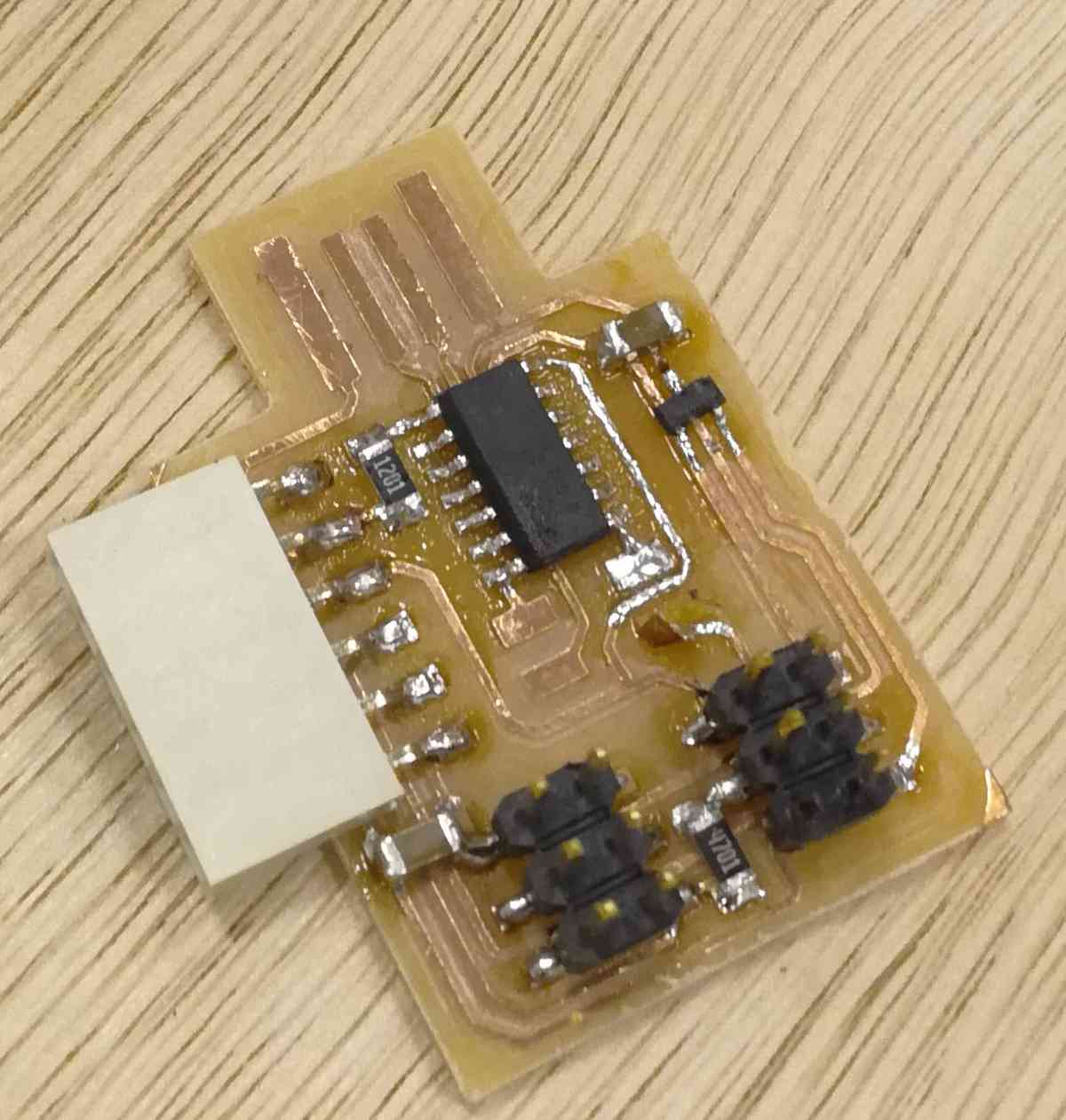
Then, to program the board, I started by connecting 2x2 pin connectors of our board to a JTAG programmer with jumper cables.
On top of connecting the 2x2 pin connectors you need to provide power to the board which can be done by plugging it in a USB port.
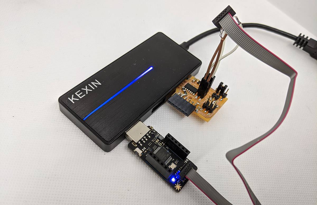
Then I verified that my computer had detected the programmer using edbg -l

When I was sure it was well connected, I uploaded the bootloader on it with :
edbg -ebpv -t samd11 -f sam_ba_Generic_D11C14A_SAMD11C14A.bin
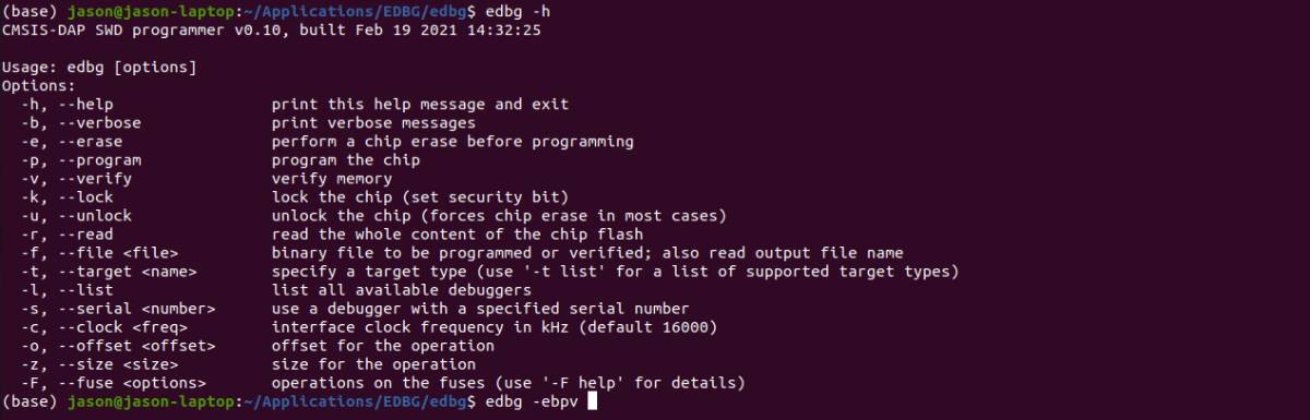
edbg -h :
edbgis the name of the program-defines the option you want to useewill erase whatever is on the microcontrollerbwill make the verbose active, meaning that it will print out messagespis there to tell edbg that we want to program the chipvto tell edbg to verify that the transfer was done without mistakes-tis the target so the microcontroller we target in this case, we soldered a samd11 so we typesamd11-fis the file that we want to upload, so the binary we downloaded
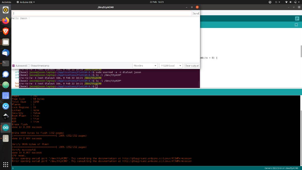
I had some issues with permissions and did not solve them properly but used sudo to get through them. It is not a good practice because you can break a lot of stuff by forcing it but it works.
sudo edbg -ebpv -t samd11 -f sam_ba_Generic_D11C14A_SAMD11C14A.bin

Erasing...  done.
Programming................... done.
Verification................... done.
It worked and now I can add programs on the chip using the USB port and the Arduino IDE.
The bootloader makes it possible to load files through the USB entry which is very convenient.
Programming : Load a program
So now to do that you can load a program. We do that with the Arduino IDE and we upload our code in C.
Here, the goal is to make this programmer translate USB into serial data.
The code we used can be found here : https://github.com/qbolsee/SAMD11C_serial
The nice thing is that it automatically detect the baudrate of the serial port.
The baudrate is the speed at which new bits are sent through the serial port.
To upload it to the chip, you need to download the ArduinoCore SAMD of Mattairtech : https://github.com/mattairtech/ArduinoCore-samd#mattairtech-dlc-core-installation
Here is a summary of the steps
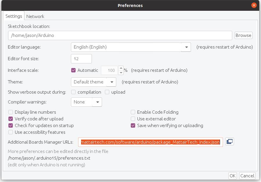
- Open the Preferences of the Arduino IDE.
- Add this URL https://www.mattairtech.com/software/arduino/package_MattairTech_index.json in the Additional Boards Manager URLs field, and click OK.
- Open the Boards Manager (menu Tools->Board-Board Manager…)
- Install Mattairtech Arduino SAMD core
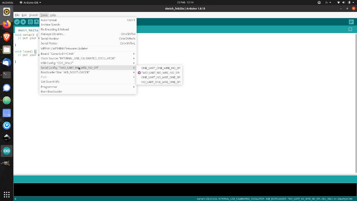
Then in tools in the ArduinoIDE, select Generic_D11C14A
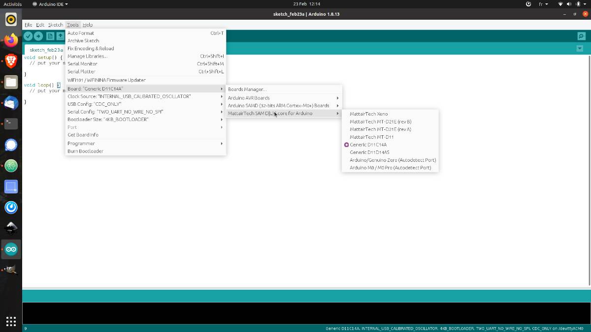
And the SerialConfig : TWO_UART_NO_WIRE_NO_SPI
We uploaded the files and I received my first custom network connections from Maxim through the serial monitor !
Addtional tests:
Voltera
We tried to make the Voltera machine from the university work but unfortunately, it was not working properly because of the ink or the nozzle probably.
The Voltera looks like a nice machine but looks also more prone to problems related to the ink. The circuits however look extremely clean !
Mods
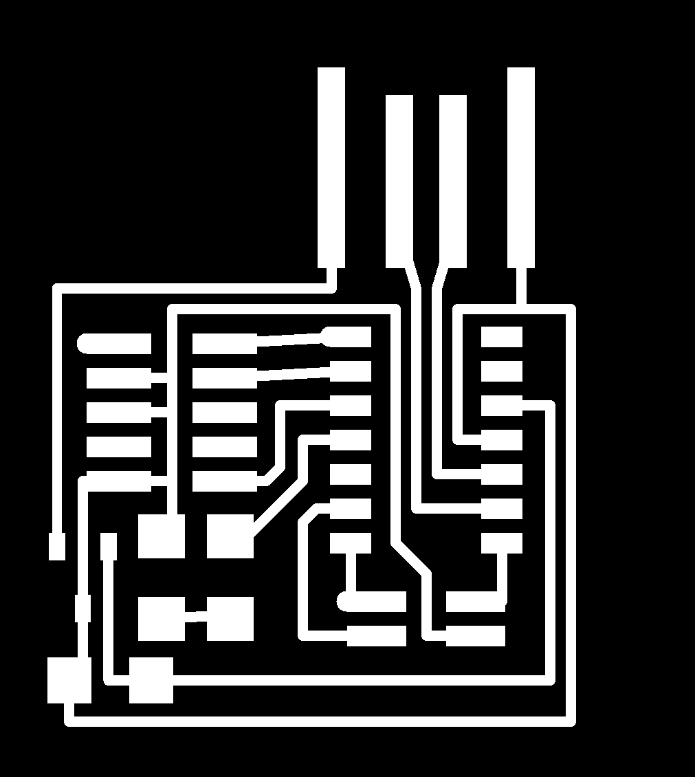
I tried using mods to make gcode from PNG.
We know that the files from Neil Gershenfeld are in 1000 DPI, so we know the scale of the picture.
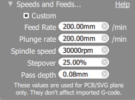
I uploaded the PNG in mods and set it up with the parameters that we use in BANTAMTools :
I did it first using the Brave browser which is based on Chrome, and the result were very weird ! Therefore I used Firefox and it went fine.
After that, I imported the files in BANTAMTools the same way I did for the gerber files but there was something wrong with the coordinate system.
After some investigation, we found that the BANTAMTools software does not recognize the gcode command “G54” and has to be removed.
So we did and it worked !
We had more issues related to the speed encoded in mods which was much too fast. There is a confusion between minutes and seconds.
I also learned that with mods we can create a custom module and save it locally increasing the speed of treatment.
Files
CMSIS-DAP.4.D11C
- traces png
- gcode for the traces
- components
- gcode for the outline
- outline png
- Python file to generate the PNG
SAMD11C14_UART-UPDI