16. Wildcard : Microfluidics
Assignment definition
Design and produce something with a digital fabrication process (incorporating computer-aided design and manufacturing) not covered in another assignment
Microfluidics :
This week, I wanted to test making microfluidics devices using digital fabrication means, especially the laser cutter.
What is microfluidics ?
Microfluidics is the handling of micrometric amount of fluid or the manipulation of fluids at small scale (milimetric).
The application are very wide, especially in pharmacy, drugs development but also in medical devices and diagnostic.
Wetting
My interest in microfluidics is more specifically aimed at automated microfluidics “powered” by hydrophilic / hydrophobic effects.
In simple terms, hydrophilic means that water “sticks to it” and hydrophobic means it does not.
In more complicated terms, it means that the wetting angle is higher or lower then 90°.
This angle depends on a lot of parameters, the surface topology, materials, charge, … It is a very deep subject and
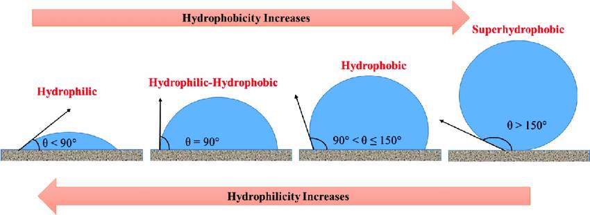
Figure from the following article
Electrowetting
Another very interesting topic in microfluidics is electrowetting. That is the modification of the wetting angle using the electric field and it opens the road to digital microfluidics.
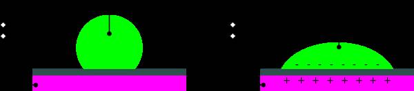
The best project I found on that is OpenDrop and it’s truely amazing !
This is only an early version, a lot has been developped afterwards and everything is open source !
However this is more complicated and requires power, high voltage (100V) and quite more preparation.
Manufacturing microfluidic chips
Different process are used in microfluidics, but because microfluidic is very dependent of the surface state and the material there are severe limitations.
A lot of methods exists and a lot of them are based on assemblies which makes it prone to fail when it is done by hand.
The simplest way to do it is using cutted paper strips, paper works as a fluidic pump, absorbing the liquids. Then, you can also use a greasy material on clean glass as greasy materials are hydrophobic and glass is (usually) hydrophilic, the liquid will stay in the boundaries marked by the grease on the glass.
Another way is to use a printer and print wax on paper, again using paper, you get other materials in the liquid (the cellulose of the paper).
Another possibility is using parafine and glass slides as showed in the following video.
Another solution is to make molds using hydrogels as a positive and cast them in PDMS.
A common material is PMMA because it’s fairly inert so does not interact with the liquid solution and hydrophilic so it pulls the fluid along the tracks.
To produce chips in PMMA two main ways exist traditionnally, milling and molding.
Milling is possible but needs to be done very slowly as the PMMA should not melt and should keep a very good surface finish. The surface finish is expressed in terms of rugosity, the rugosity is the “noise” on the surface, how smooth it is or rather how not smooth it is.
Therefore rugosity is expressed in meter or rather micrometers.
The best way to produce chips in PMMA is injection molding because then, the surface finish depends on the mold and can be extremely good.
My interest when I saw how clean the laser cuts in PMMA was to see how it could work for microfluidics.
I also wanted to test milling a piece this week and I made the design to do it but I realized the set up of the parameter would take too much time.
I did not have a specific circuit in mind but rather wanted to see how far the liquid would go naturally simply using a laser cut PMMA block.
I have read different articles including the following and as expected the trick is to defocus the laser to avoid making a sharp cut but rather a groove.
The first test to make this process complete are to define the parameter space possible, then characterize the parameters and their effects on groove depths and width as well as rugosity.
I don’t have the instruments to measure anything more than the progression of the liquid in the chip but already testing the different parameters will be plenty of work.
My intended process was :
- Design a chip in Fusion360
- Export in DXF
- Import in Inkscape
- Send to laser cutter
- Adjust parameters on Epilog Dashboard
- Close the chip with chloroform and a second sheet of PMMA
- Use water and colorant to visualize the flow of liquid
But I did not get master the process yet so I started simpler by designing simple shapes in Inkscape directly and experimented on those. On top of that, I did not get chloroform in time for my tests so I tested them in another way.
- Design a Inkscape
- Send to Epilog Dashboard
- Adjust parameters on Epilog Dashboard and on the laser cutter
- Laser Cut PMMA
- Use water and colorant to visualize the flow of liquid
Because I did not have a top part in most cases, I used gravity as the driver of the fluid by tilting them slightly.
Testing
I wanted to test two things: Rastering and vector cutting with the laser cutter.
Different hypothesis based on the papers that I had read :
Rastering would make the substrate
- more hydrophilic
- more hydrophobic
Defocusing the laser would decrease the rugosity and that would make the substrate
- more hydrophilic
- more hydrophobic
So I started experiments with the following drawings and below are the results.

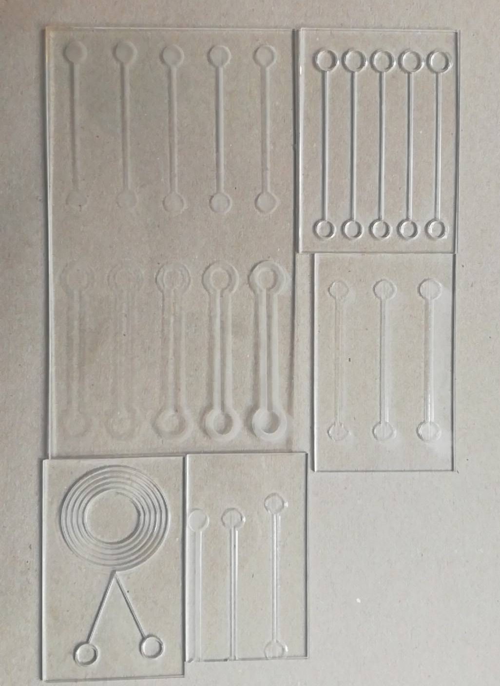
Because of the defocusing, I misplace the edge cut one of the boards but it still worked well and actually was useful as it provided and air entry when I closed with another piece of PMMA.
I managed to find good parameters for the vector technique with a defocus of +5 mm, speed 20% and power 70%. The others were not satisfying at transporting the liquid in the groove or even pulling it.
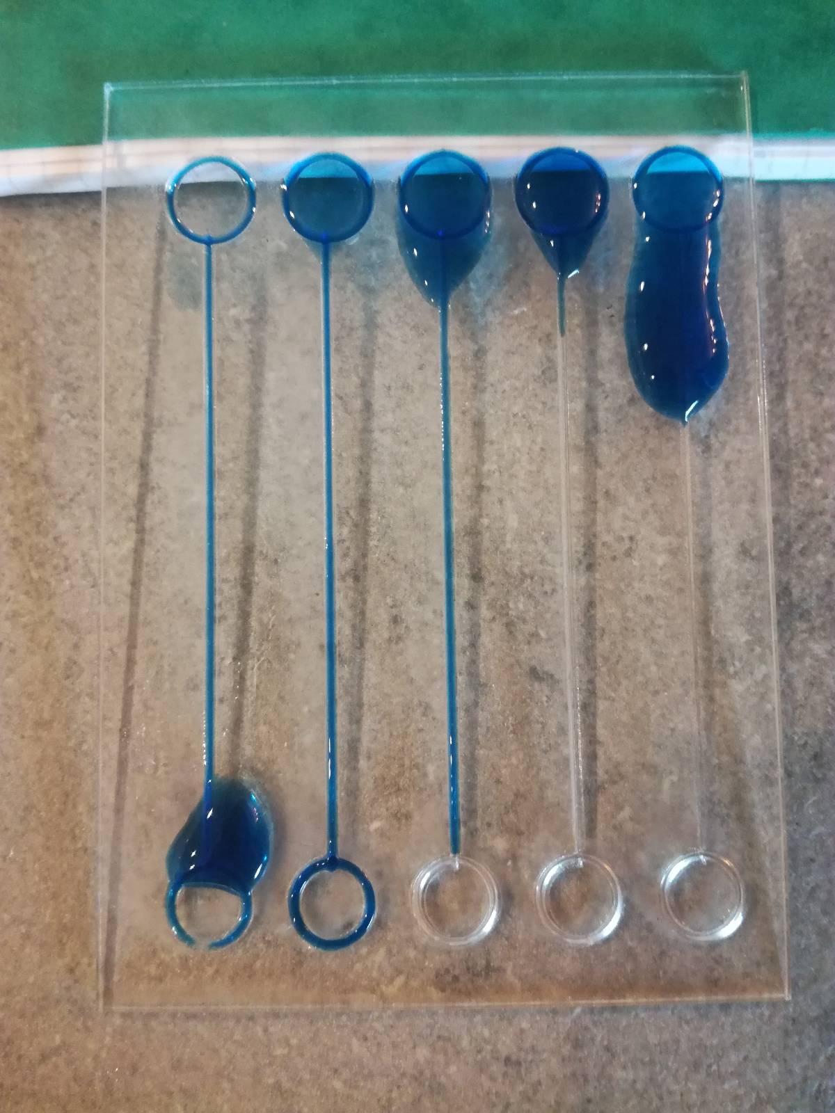
So I tested that on a more complicate design to see if it could go back up against gravity, and it worked good enough !
I tried to raster the PMMA and expected it to be less hydrophilic because of a phenomenon called the “fakir effect”, but the opposite happened.
My first test were without any defocusing here, 1200 DPI, 50% speed and 50% power but with different saturation in the colors.
I tested first with the rastered area as a border, but it clearly did not work !
Then as a guide which did not work very well either.
So I tried defocusing with different height 0mm 5mm and 10mm with higher power to compensate the defocusing :1200 DPI, 20% speed and 70% power.
It worked much better !
So I tested on a flat surface closing it with another piece of PMMA and the results were satisfying !