Project Development
Features
The features I want for this 3D scanner are :
- Take pictures of an object at different angles
- Be easily transportable and storable
- Display the status of the scanner on an OLED screen
- Control the scanner through a rotary encoder
Here’s a comprehensive view of the system that I designed.
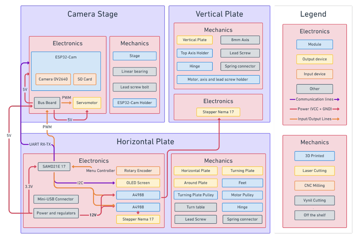
If you want to navigate it, just check it here below.
Mechanical
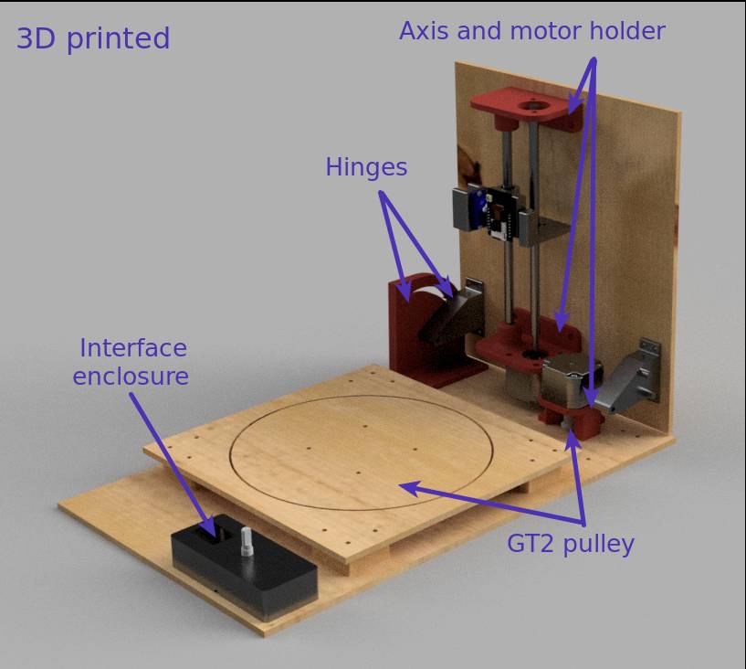
I designed most mechanical components including the hinges to retain flexibility.
For the prototype, I decided to stick to 3D printed parts and laser cutted planks to fabricate them in the fastest way possible. I would like to mill the casing but I will do that only if I have enough time remaining.
Regarding the active components, I added as many of them to my Fusion360 model as I could to reflect as best as I can the final look and also to design my pieces at the right dimensions.
However I encountered problems multiple times as the dimensions of the 3D model I had imported did not always match the ones I had physically.
To download parts to add to my CAD model I searched the web and found useful parts on website such as GrabCAD, STL Finder, …
But before looking online, I used McMasterCarr library which is included in Fusion360 itself and very convenient. They have a lot of parts in imperial units rather than metric but still often works.
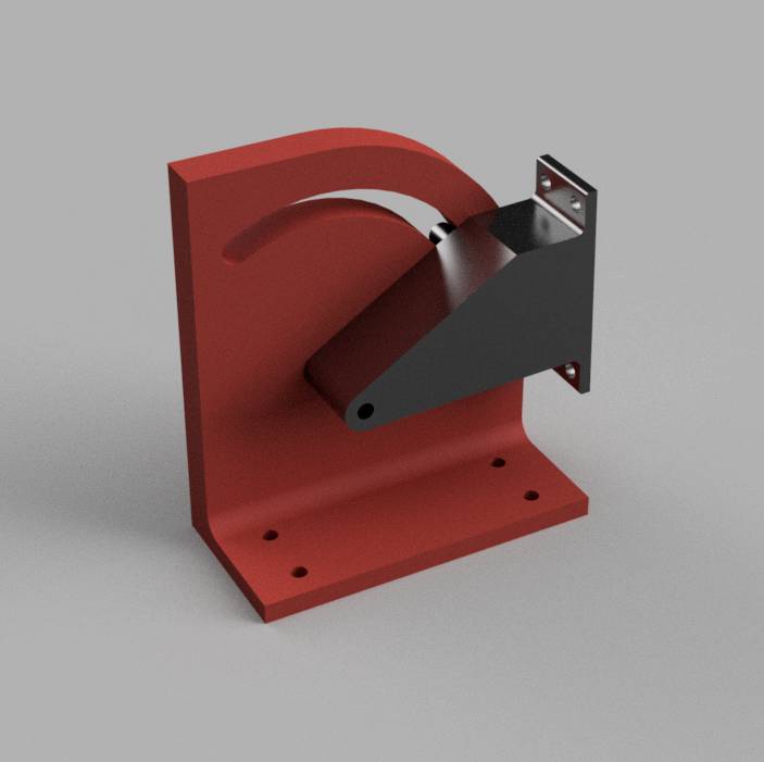
I designed the hinges so that they allow for the movement and minimize dead space while avoiding collisions between the motor and the botton plate.
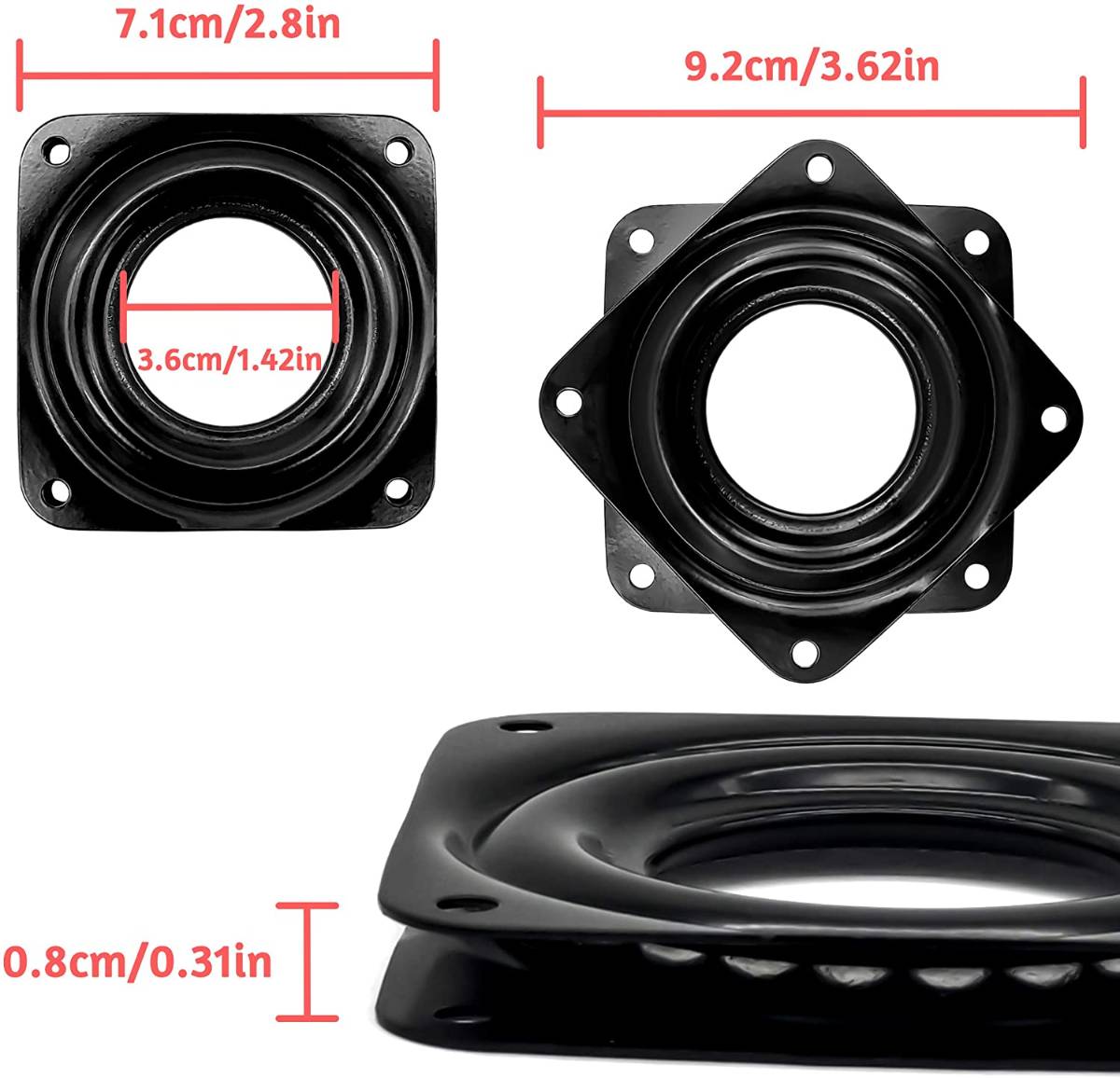
To make the turning plate turn, I decided to use a turntable also called lazy susan (for an unknown reason). It has the advantage of being very resistant but does give a little game so it’s not perfectly parallel.
Also, the 3D model I imported for it were wrong and I had to redraw it using the proper dimensions.
To actuate the turning plate, I decided to follow the same solution as Quentin and use a timing belt. This allowed me to get the turning plate lower by placing the motor further and minimize the space taken by the whole scanner.
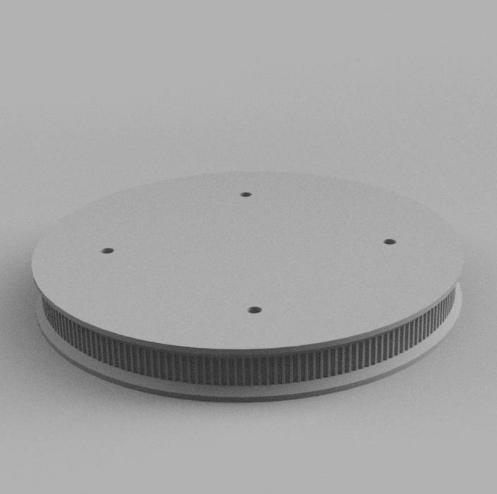
To design the pulley, I tested different solutions, starting with the one Quentin used (an online gear generator) then I tried a Fusion360 add-on to generate gears but I was not satisfied so I kept looking and I found a GT2 parametric pulley authored by Fusion360 people which fitted perfectly my needs.
I adjusted the size by adding parameters and designed large pulley to fit the turntable.
I then designed a custom pulley as the ones I had ordered where not of the right diameter for my motor axis, and I also designed a motor holder to fix the motor upside down to align the two pulleys in the same plane.
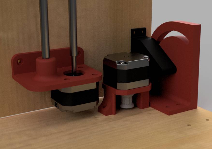
For the vertical axis, I decided to raise and lower the camera stage using a lead screw and to keep the alignment using a simple cylindrical axis. The motor is here fixed to the vertical plate and the hinges are “perfectly” designed to limit the deadspace under it.
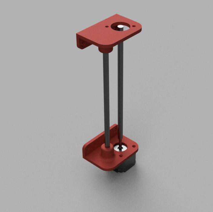
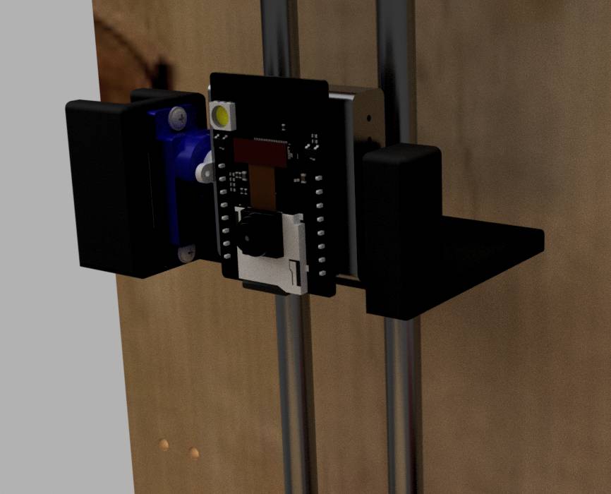
Finally, for the camera stage, I made a stage carrying a servomotor, itself carrying the ESP32-Cam. I attached fixation holes for the lead screw moving nut and a hole for the linear bearing for the axis.
Electronics
Regarding the electronics, I needed different elements:
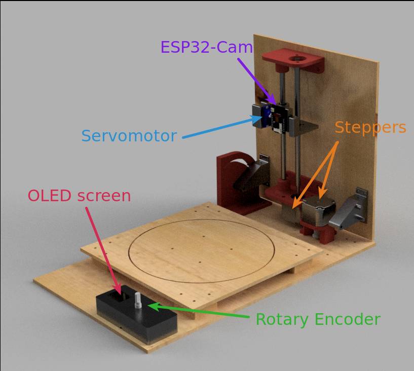
- ESP32-Cam : it is the easiest way I know to have an all-in-one camera, plus it provides wifi and bluetooth which is convenient if I ever decide to use it.
- Motor controllers : I wanted to use nema steppers, for my purpose but I now realize that it might be overkill as my application does not require a lot of torque. Anyway I have already planned everything with these so I’ll stick to it.
- LED screen : I decided to use an I2C OLED screen for no better reason than I had one on hand but if I could I would go for a I2C LCD screen as they are bigger and more appropriate for menus similar to 3D printer ones.
- Rotary encoder : it’s a classic for embedded menu selector in any 3D printer so I thought it would be perfect.
- Servomotor : to control the vertical angle of the camera
- Main controller : The ESP32-CAM has no pins available besides the TX-RX pins and thus is very limited in terms of control. To control the motors, servomotor, screen etc. I needed another board. Now I had to choose the family and the microcontroller.
Choosing the microcontroller
I new I would be tinkering and I knew I wanted to have the possibility to collect the images through USB so using a microcontroller providing native USB support would be very convenient. The ARM family was thus a good choice. I had already tinkered with the SAMD family and decided to go for that one.
I had already designed boards with the SAMD11C14 but it had way too little pins for me so I needed a bigger one.
How many pins do I need ?
| Component | GPIO Pins required | Other pins |
|---|---|---|
| OLED screen | 2 (I2C: SDA, SCL) | 3.3V & GND |
| A4988 controllers | ( > 2 and < 6 ) *2 motors | 3.3V & GND , 12V & GND, Motor pins |
| Rotary Encoder | 3 (2 rotary + 1 button) | 3.3V & GND |
| Servomotor | 1 PWM | 5V & GND |
| Serial communication with ESP32 | 2 (RX & TX) | n.a. |
Thus that makes it a minimum of 12 pins and a maximum of 20 pins including 2 serial ports (I2C and RX-TX). The number of pins used depending on the amount of control you want on the A4988 controllers.
The SAMD11C14 was not enough but the SAMD21E17 did. Because I wanted to have the possibility to code it all in Python, I made the second board using the SAMD21E18.
Well just around that time I was wondering whether to use a single board handling everything or to make multiple smaller boards, simpler to debug.
I think both solutions would have been good but I sticked to making one single board as it was not so much.
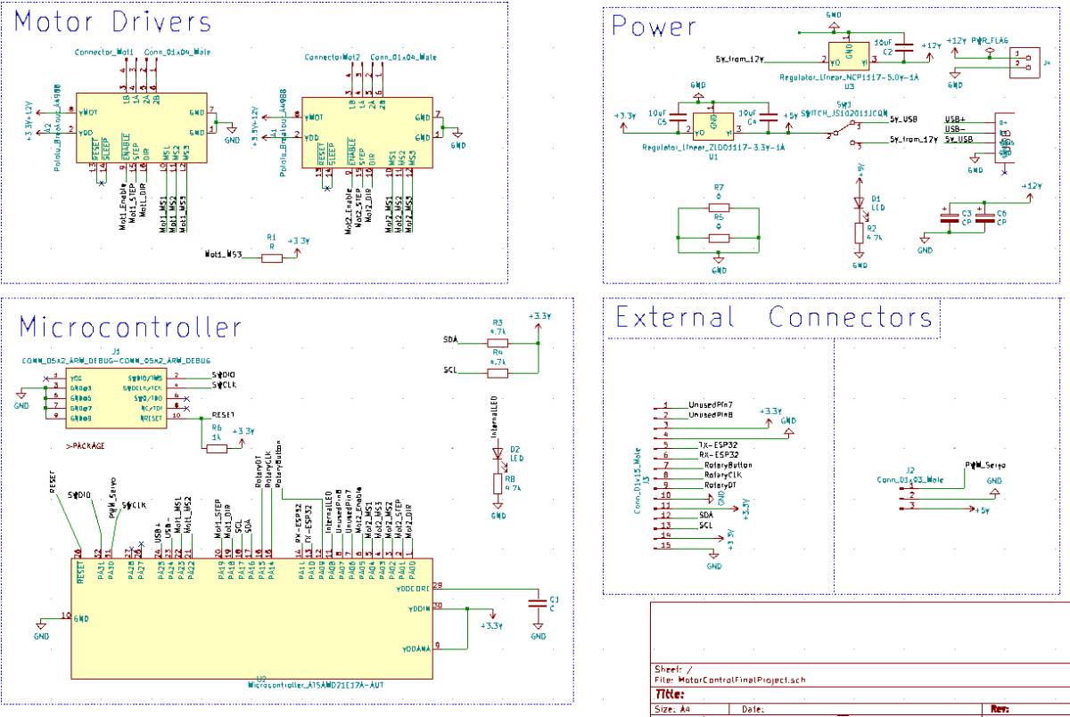
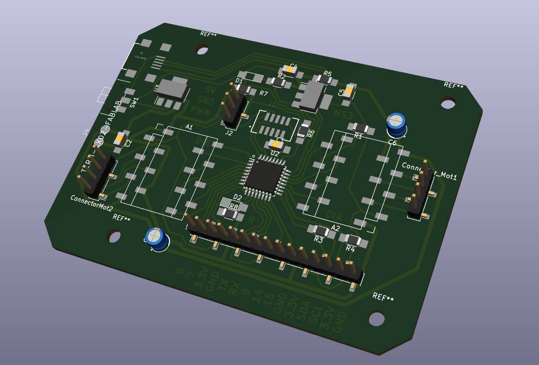
This was the largest circuit I had designed so far, so I also made it the cleanest so far to avoid getting confused.
To be honest, my first routed version was quite ugly and impractical especially when I realized I had completely forgotten to put the JTAG connector.
I could have avoided using the JTAG pins by pre-programming the board but I preferred adding them anyway as this makes it more versatile, especially for the SAMD21E18 version for which I can switch from C to Python by changing the firmware.
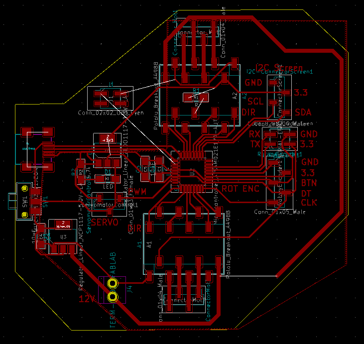
Routing the circuit took me quite some time as there are 3 different power lines (12V, 5V and 3.3V) and that I wanted to be able to power the board simply through USB even when the 12V is not connected.
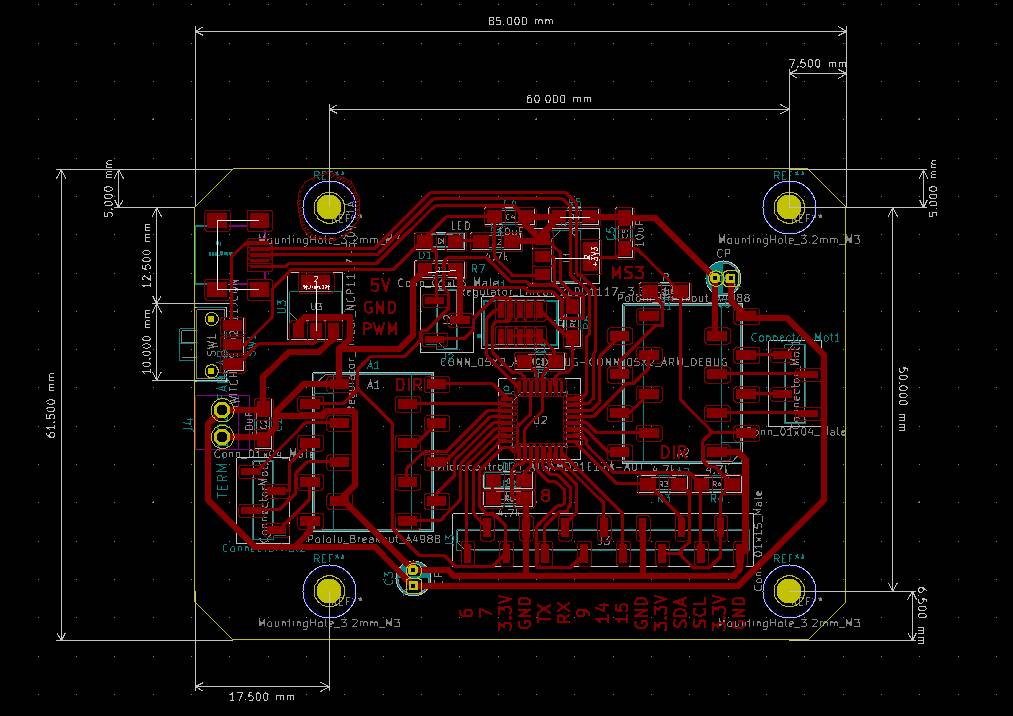
I had a couple of issues milling the board as the planeity of the FR1 boards in our Bantam machine is not always great and I had to use a 1/64” to get in between the SAMD21E17 pads so I could not increase the depth too much.
Then I loaded the bootloader and it went fine.
Then when I connected the board to my computer it did not work… Looking into it, we realized I had confused the logical pin numbers and physical pin numbers for the USB connections …
I fixed the USB connections and I was very hopeful that it would work but it still did not work. So I desoldered the microcontrollers to check for other issues and also made a second board. I resoldered the microcontrollers and populated the other boards with the minimum power components, JTAG connectors and USB plug and microcontroller but it still did not work …
Two boards and none are detected but they accept the bootloader, what could it be … I have followed the guidelines, and did put capacitors everywhere, before and after each regulators …
I was a bit desperate because nobody could figure out why it was not working and I already made a new board so I figured it must have been a design issue which I did not understand.
In a last attempt I figured I could try putting a capacitor closer to the SAMD21 and … IT FIXED IT !
So I lost some place on the board and I should update the PCB layout but my 2 boards were now working !
With the boards made, I quickly designed spacers to fix it without breaking the 2 electrolytic capacitors I had fixed below the board.
I then tested every function with example code to verify that every function was working : Motor control, I2C and rotary encoder.
Programming
Now comes the programming !
Let’s infuse some intelligence in the copper !
Let’s take our list of features:
- Take pictures of an object at different angles
- Be easily transportable and storable
- Display the status of the scanner on an OLED screen
- Control the scanner through a rotary encoder
Now we need to break them down as these features are quite high level and based on a number of assumptions that we need to explicit.
1. Take pictures of an object at different angles
The activities required to do this are:
- Take a picture
- Store a picture
- Transmit a picture
- Move the vertical motor to a given height
- Move the rotary motor
- Adjust the camera angle through the servomotor
Ok, that’s a good start but actually now that I am here, I realize that to move the vertical motor to the appropriate position, I need to know it’s position and therefore, I need to add a homing system.
2. Be easily transportable and storable
This is dealt through mechanical features.
3. Display the status of the scanner on an OLED screen
What are the important information to display to the user ?
The scanner has as far as I see it now 2 statuses :
- Scan ongoing : if so, display the progress on a progress bar
- No scan ongoing : otherwise, display the menu and listen to instructions from the wifi interface.
What should the menu contain ?
- Start a scan
- Homing
- Scan options
- Scan resolution : a proxy for the number of pictures taken
- Object height
- Change the Wifi network
- Find the webserver address
4. Control the scanner through a rotary encoder or Wifi
Generally speaking we need a control function and two communication functions, one for wifi and one for the rotary encoder.
- Instruction function (main function)
- Wifi communication : this can be done through javascript sending a request to the ESP32Cam then transmitting it via Serial to the SAMD21E17 board.
- Rotary encoder communication : This can be done via a menu using the OLED screen, the rotary encoder to navigate and the included button to select.
Files
Mechanics
To demonstrate capability in FreeCAD, I decided to make one component in FreeCAD.
STL files for 3D printing are too large to include.
Electronics
Code