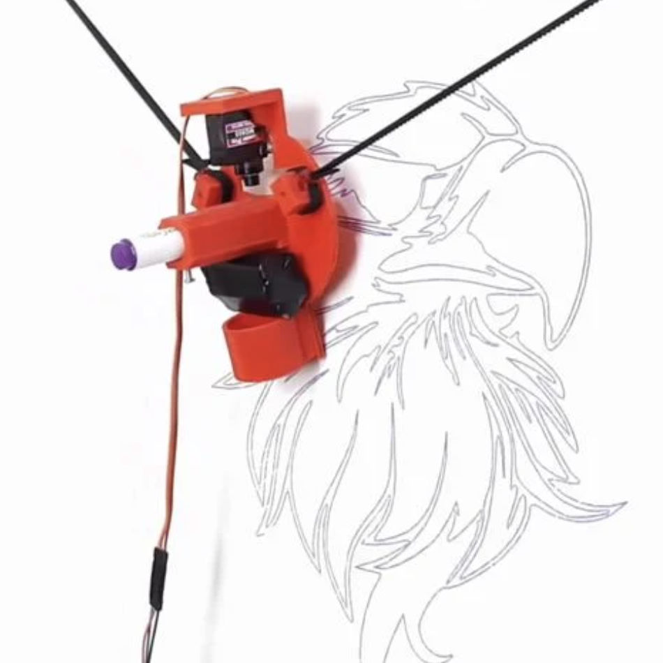
Machine Design Concept
We decided to make a machine to draw on the wall of Inno Fab's incoming space.

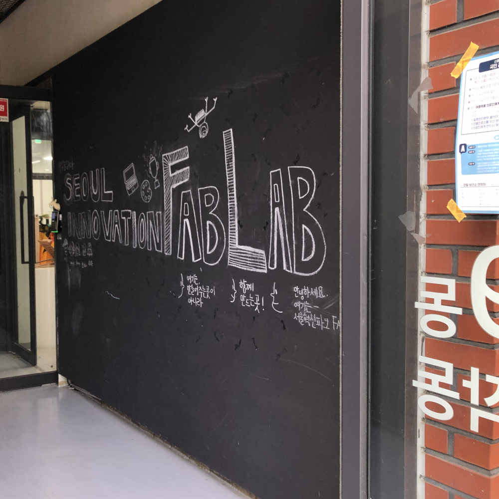
- The walls of the space were plastered to be decorated with chalk, so we tried to make a drawing machine with chalk, unlike the previous one.
Here, the problem with using chalk is that the more we use it, the more it wears out, so we need to make it come forward.
- And we were planning to make a different board without using the existing Arduino board, and also make boards for each stepper motors.
- Then We was going to use SPI to do networking.
- we decided on the model of the machine we were going to make.
Member Tasks
We divided Inno Fab's students into a software team(Yunjo, Jihwan, Seokmin) that would make and code boards and a hardware team(Jeonghwan, Yunje, Hyunho) that would create the overall external frame of the drawing machine.
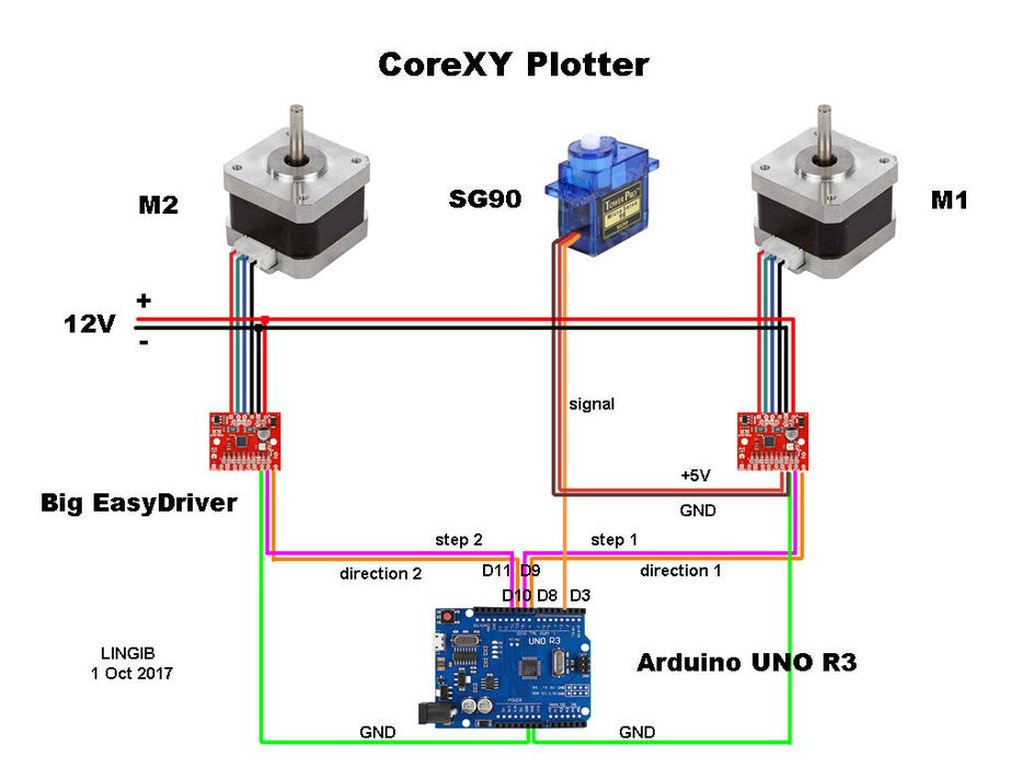
Schema of Connections
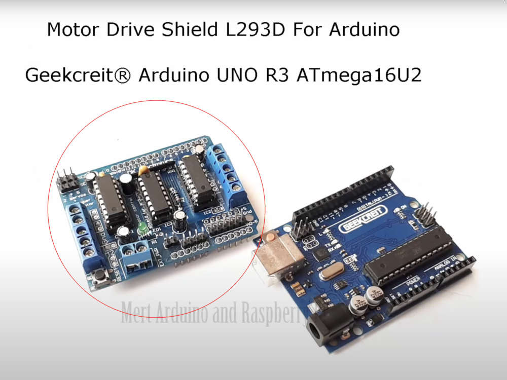
- We first tried to test using the Arduino board as we used in the tutorial.
- But we didn't have the "L293D Motor Drive Shield" used in the tutorial, so we decided to use another motor drive.
- So we found "GY-4988" in our lab and decided to use it.
- It was very similar in function to the commonly used "A4988 Motor Dive Board."
- So we used A4988 to find examples of stepper motor movement. I referred to the YouTube video.

- The test was successful.
- And we found an example site of using two stepper motors and one servo motor.
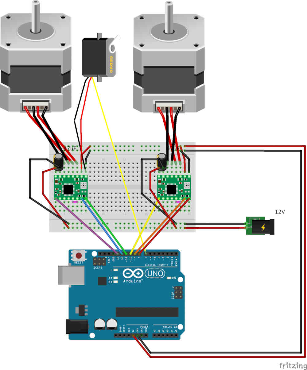
Reference Site
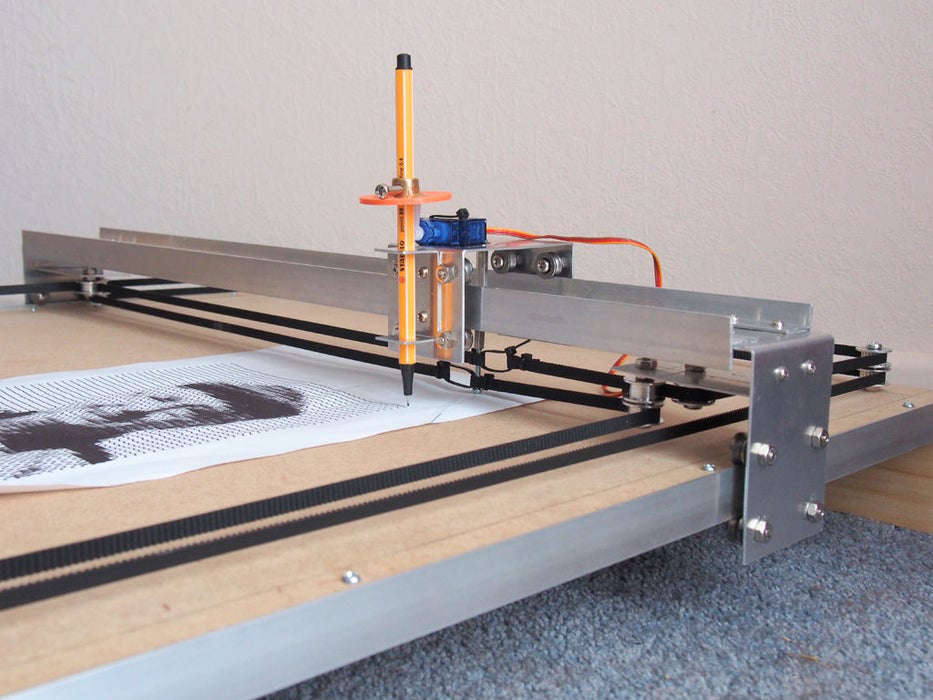
- In this tutorial, the motors of the machine being the model and the boards were connected in a similar way and there was a schema that could be referenced for programming.
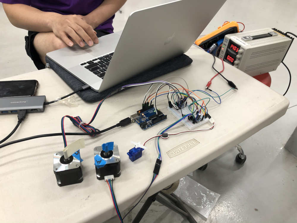
- And we tested it after making the same connection as it.
Apply to Model (about the connection schemas)
We proceeded in the following order.
1) First, download the Polargraphcontroller compression folder through the reference site.
2) Add specific files to each storage space in Arduino and Processing.
3) Insert the Arduino code into the Uno board.
4) Turn on the processing and run it to draw along the tutorial.
I added only the part that changes the code to my documant, and the part that deals with processing will be referred to the documents of Yunjo and Seokmin.
- In order to use "GY-4988" instead of "L293D Motor Drive Shield," the code had to be modified according to the instructions in the Arduino code used in the tutorial.
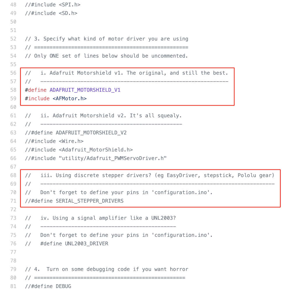
- We defined the code for the motor boards(GY-4988) used and then modified the information on the pins to which the motors were connected.
Before
// 3. Specify what kind of motor driver you are using // ================================================== // Only ONE set of lines below should be uncommented. // i. Adafruit Motorshield v1. The original, and still the best. // ------------------------------------------------------------- #define ADAFRUIT_MOTORSHIELD_V1 #includeAfter// ii. Adafruit Motorshield v2. It's all squealy. // ---------------------------------------------- //#define ADAFRUIT_MOTORSHIELD_V2 //#include //#include //#include "utility/Adafruit_PWMServoDriver.h" // iii. Using discrete stepper drivers? (eg EasyDriver, stepstick, Pololu gear) // ---------------------------------------------------------------------------- // Don't forget to define your pins in 'configuration.ino'. //#define SERIAL_STEPPER_DRIVERS // iv. Using a signal amplifier like a UNL2003? // -------------------------------------------- // Don't forget to define your pins in 'configuration.ino'. // #define UNL2003_DRIVER // 3. Specify what kind of motor driver you are using // ================================================== // Only ONE set of lines below should be uncommented. // i. Adafruit Motorshield v1. The original, and still the best. // ------------------------------------------------------------- //#define ADAFRUIT_MOTORSHIELD_V1 //#include// ii. Adafruit Motorshield v2. It's all squealy. // ---------------------------------------------- //#define ADAFRUIT_MOTORSHIELD_V2 //#include //#include //#include "utility/Adafruit_PWMServoDriver.h" // iii. Using discrete stepper drivers? (eg EasyDriver, stepstick, Pololu gear) // ---------------------------------------------------------------------------- // Don't forget to define your pins in 'configuration.ino'. #define SERIAL_STEPPER_DRIVERS // iv. Using a signal amplifier like a UNL2003? // -------------------------------------------- // Don't forget to define your pins in 'configuration.ino'. // #define UNL2003_DRIVER
Make Main Board
- We decided to use Satshakit Board to replace board Arduino Board.
- I made a satshakit cnc board.
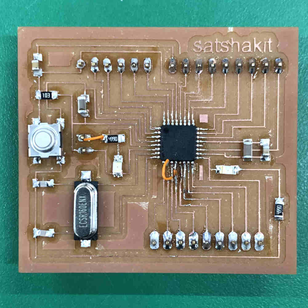
- And I went through this part of satshakit site to use the satshakit cnc board.
- I tried uploading the code to the Satshakit using an Arduino as an ISP, but got an upload error.
- I switched to using my trusty FabISP and it worked without any problems.
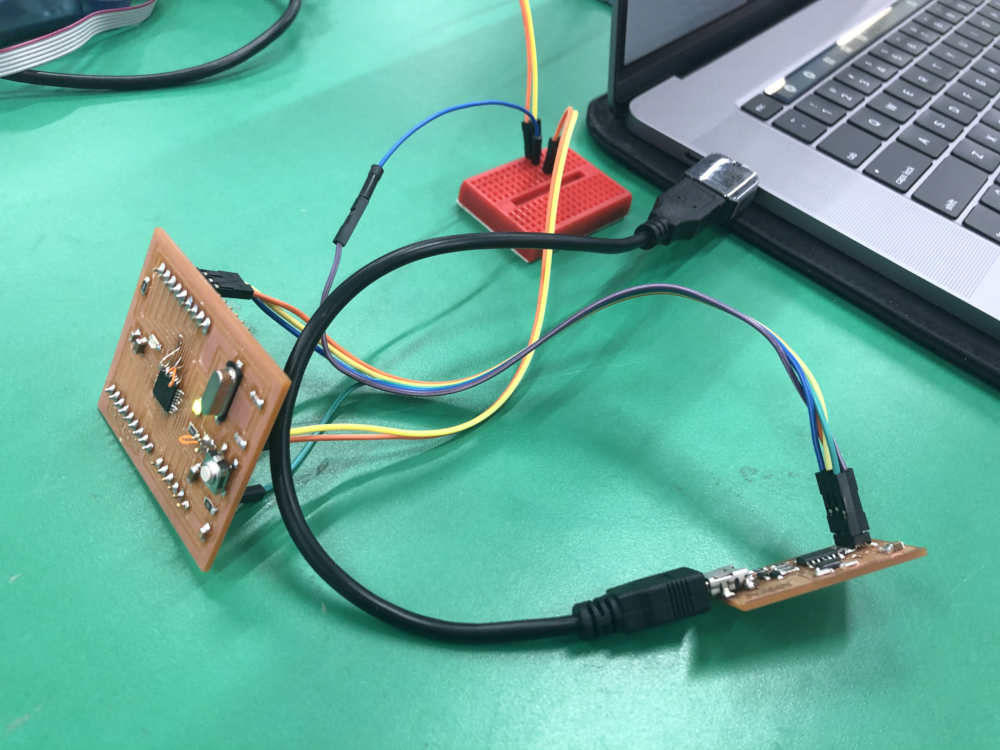
- Tested the satshakit cnc board
Make Sub Board for Motor Drive
- There were three kinds of motor drive components in our lab.
- One was the complete motor drive(L293D) of H bridge, the other was the half-motor drive(A4953) of H Bridge, and the last was the motor drive with the same functionality as the "GY-4988" we used to test.
- I chose H bridge's motor drive, and decided to use ATtiny1614 as a micro controller. (I referred to the motor drive board that Jeonghwan made at Output Week. I used other components to try using components that Jeonghwan didn't use.)
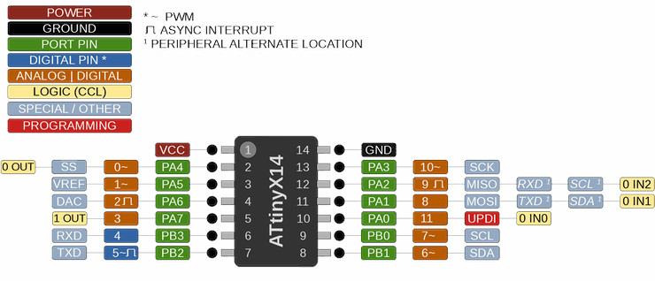
ATtinyX14 14 Pin Series Pinout
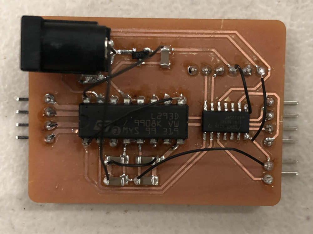
- And I made a motor board
Schematics
Footprints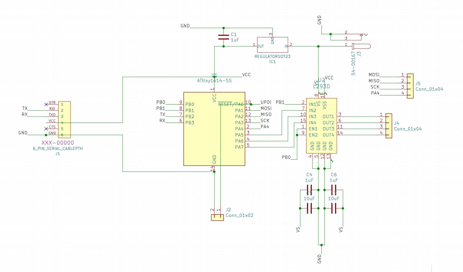
PCB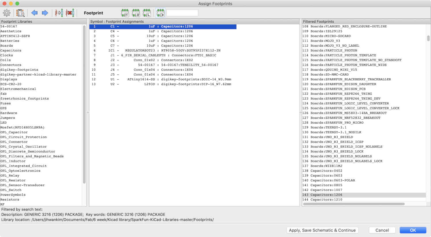
Motor Drive Board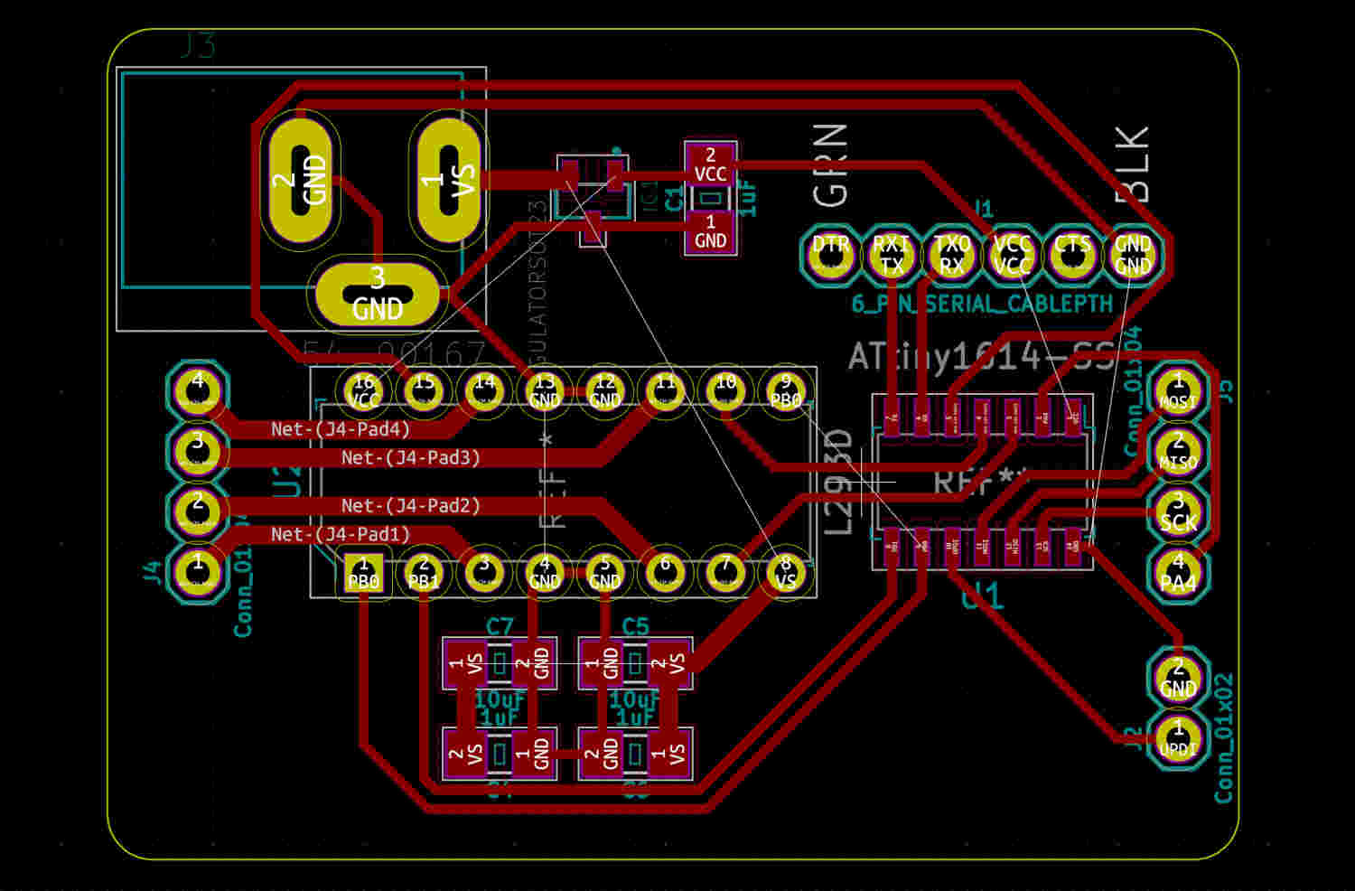
Motor Board Components
- 1) Microcontroller : ATtiny1614
- 2) Motor : 1 x 4 pin female connector
- 3) Power : Jack (12V)
- 4) Power Regualtor : RT9058-50GV(5V, 0.1A)
- 5) SPI : 1 x 4 pin male connector
- 6) FTDI : 1 x 5 pin male connector
- 7) UPDI : 1 x 2 pin male connector
Why I choose to add the capacitors to my motor boardI added a capacitor for the L293D IC because the stepper motor is an inductive load. So, it develops a back EMF when supplied by a voltage. There can be fluctuations of voltage while using the motor say when suddenly we take a reverse while the motor was moving in some direction. At this point the fluctuation in voltage is quite high and this can damage the IC. Thus, we use four capacitors that help to dampen the extreme variation in current. (Reference Site)
Why I needed to calculate the trace width on my motor board?The voltage for the motor is 12V, and the copper wire must be wide enough for sufficient current to flow. That's why I had to know how wide copper wire I needed. The calculation found that a width of about 0.8mm was needed. (PCB Trace Width Calculator)
Controlling a Stepper Motor With an H-Bridge (From lastminuteengineers.com)As L293D IC has two H-Bridges, each H-Bridge will drive one of the electromagnetic coils of a stepper motor.
By energizing these electromagnetic coils in a specific sequence, the shaft of a stepper can be moved forward or backward precisely in small steps.
However, the speed of a motor is determined by the how frequently these coils are energized.
Below image illustrates driving stepper with H-Bridge.
Learning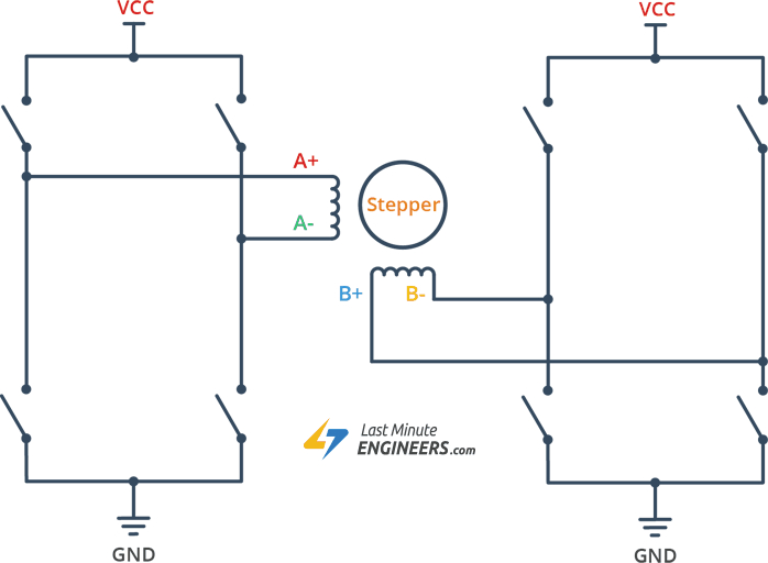
So I understand that there are four pins in the stepper motor and through those pins must be supplied with a certain sequence of power to the coils of the motor to operate the motor. Therefore, four digital input pins are needed to control each pin.