Design
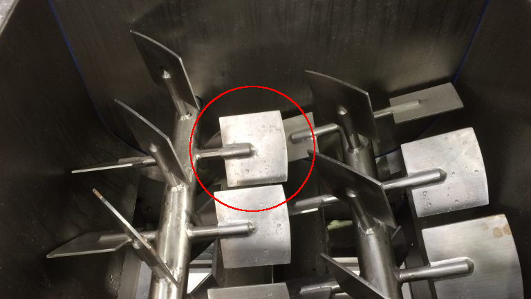
I decided to make a blade of mixing paddle included in my final project. (Similar to the image below)
Fusion 360
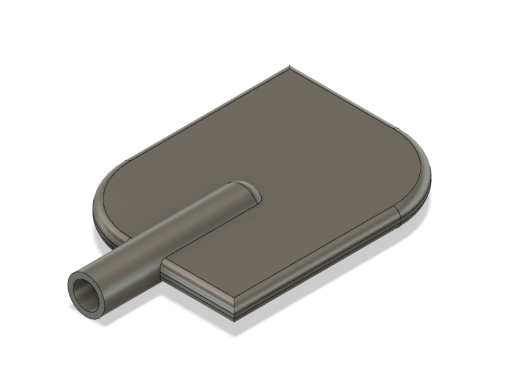
- I designed the last object to cast.
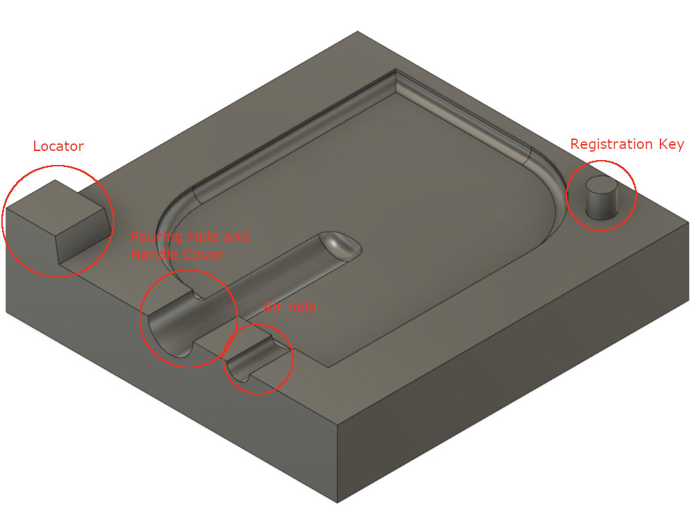
- And designed a frame for the object. (The method is to cut the object to be cast using a combine function after overlapping with the box to be molded.)
- I made a part to indicate the direction of the two frames when they are engaged, the coupling part so that the frame wouldn't rotate, a hole for the casting material and a hole for air to come out.
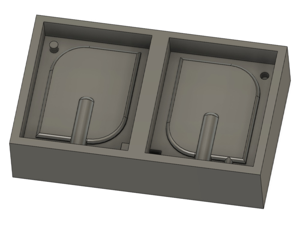
- And I used the combine function again after overlapping the frame in my wax-sized box.
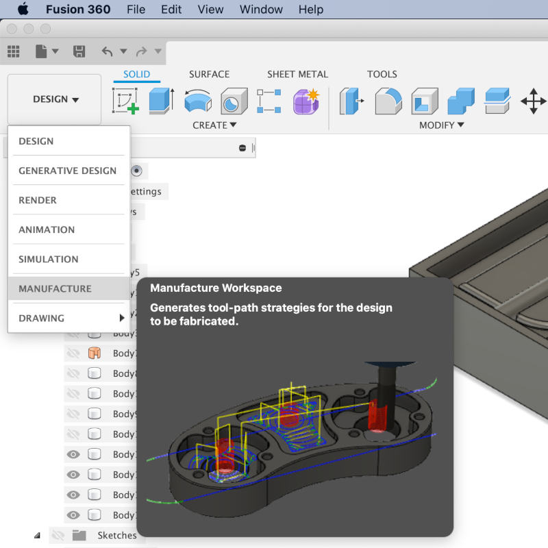
Manufacture (Fusion 360)
- Entered the manufacture.
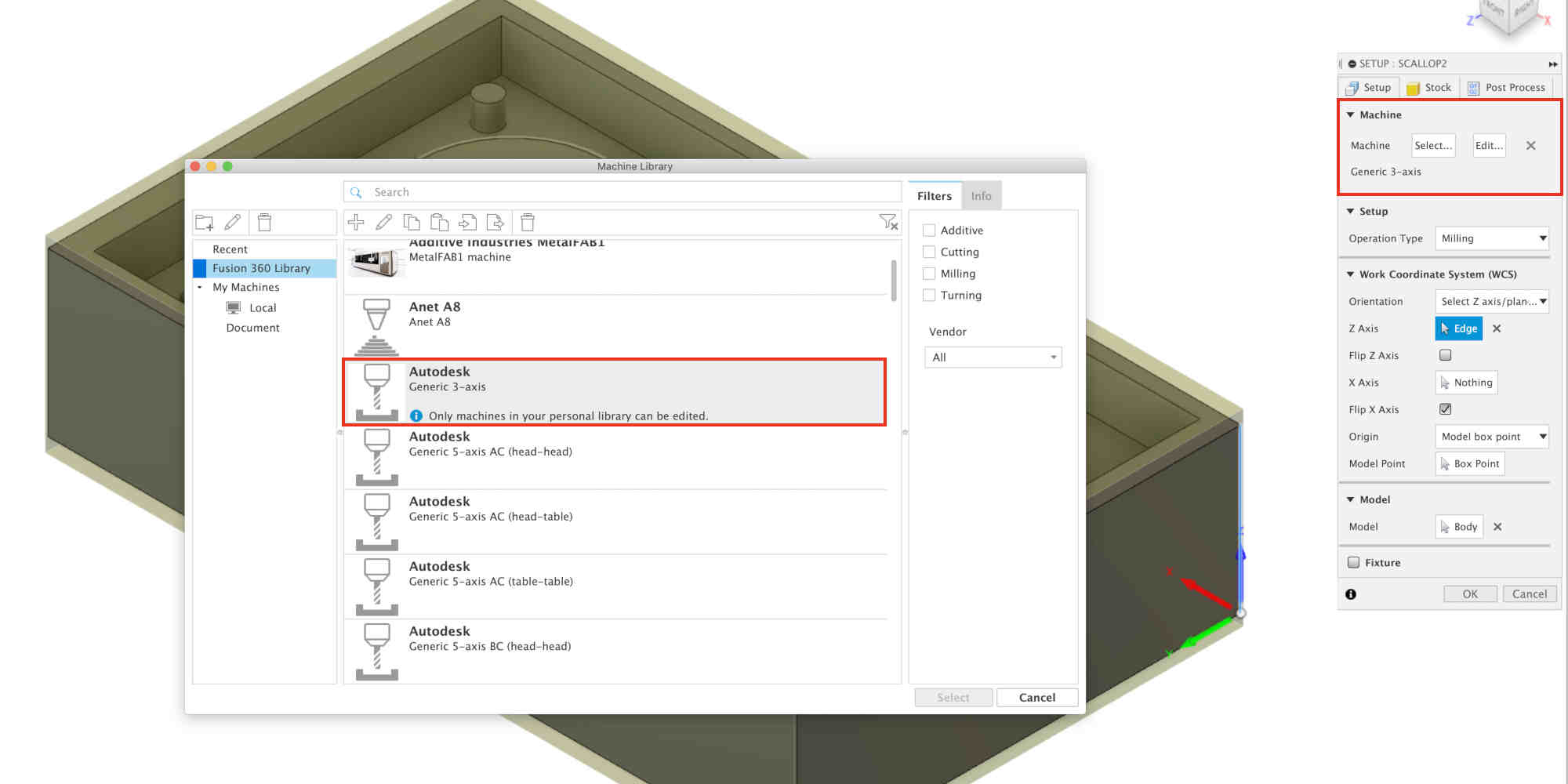
- Made a new setup.
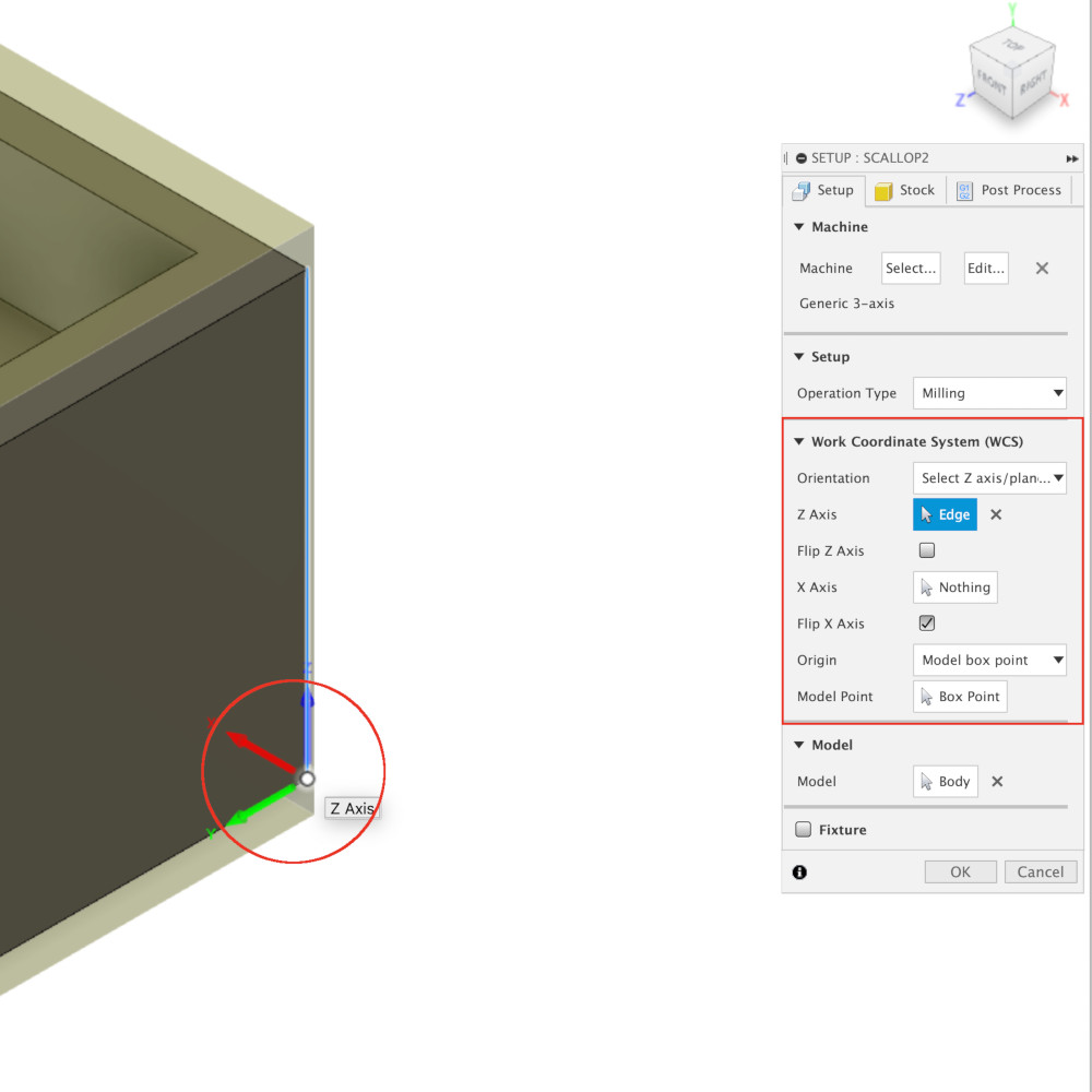
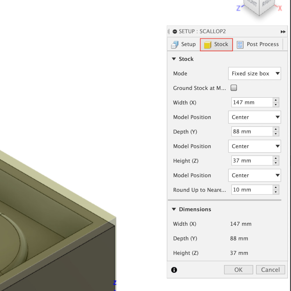
- Selected the machine to use, set the origin and axis, and the size of the Wax to use.
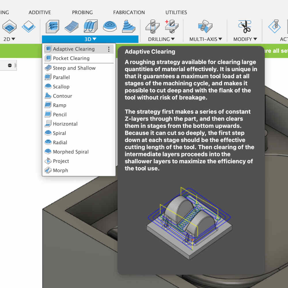
- First, I made toolpath using
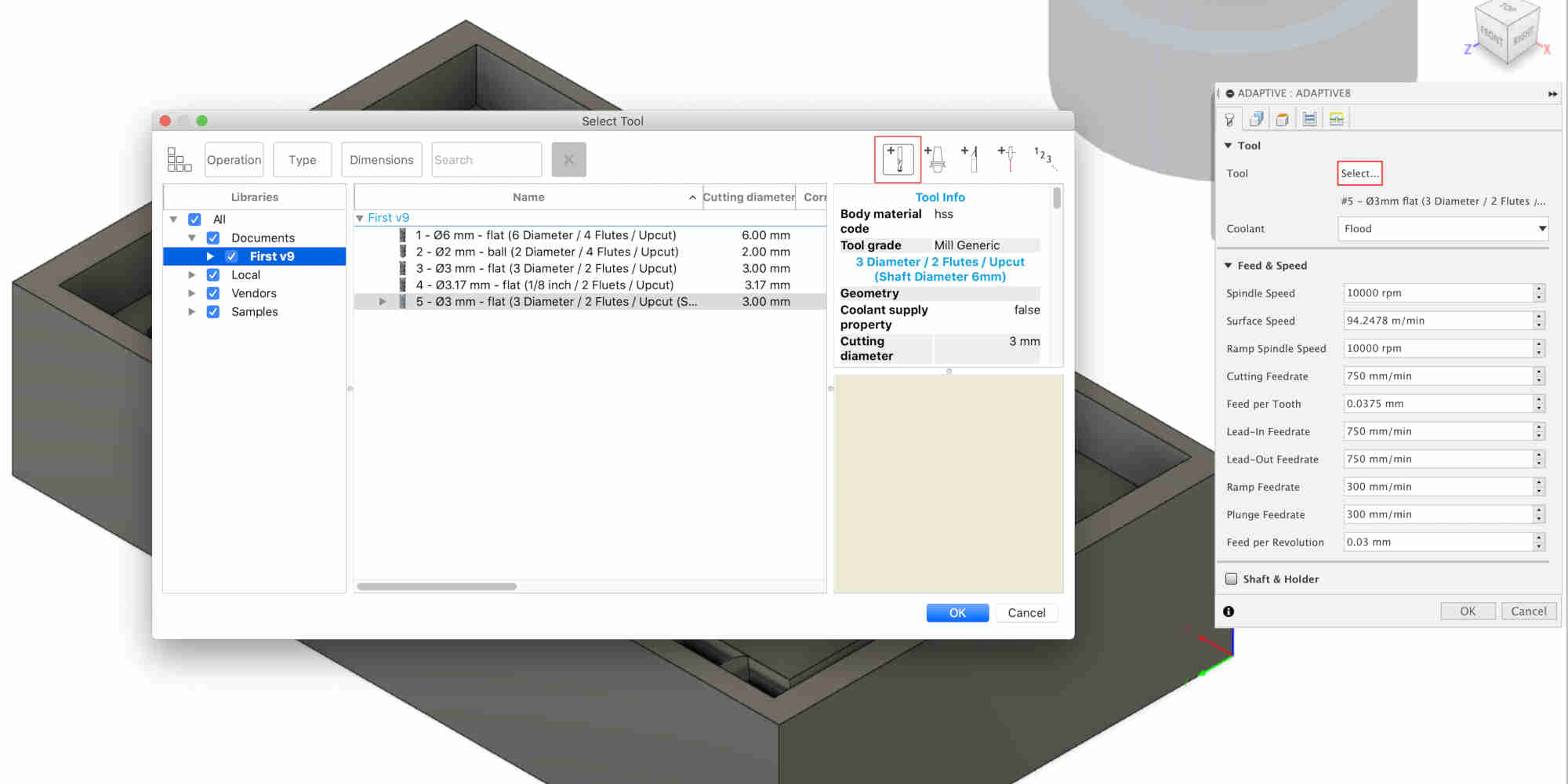
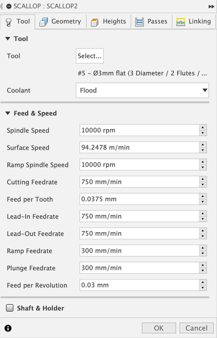
Adaptive Clearingfunction in3DOption.- 1) When making toolpath, the first thing to do is to choose the appropriate endmill for my design.
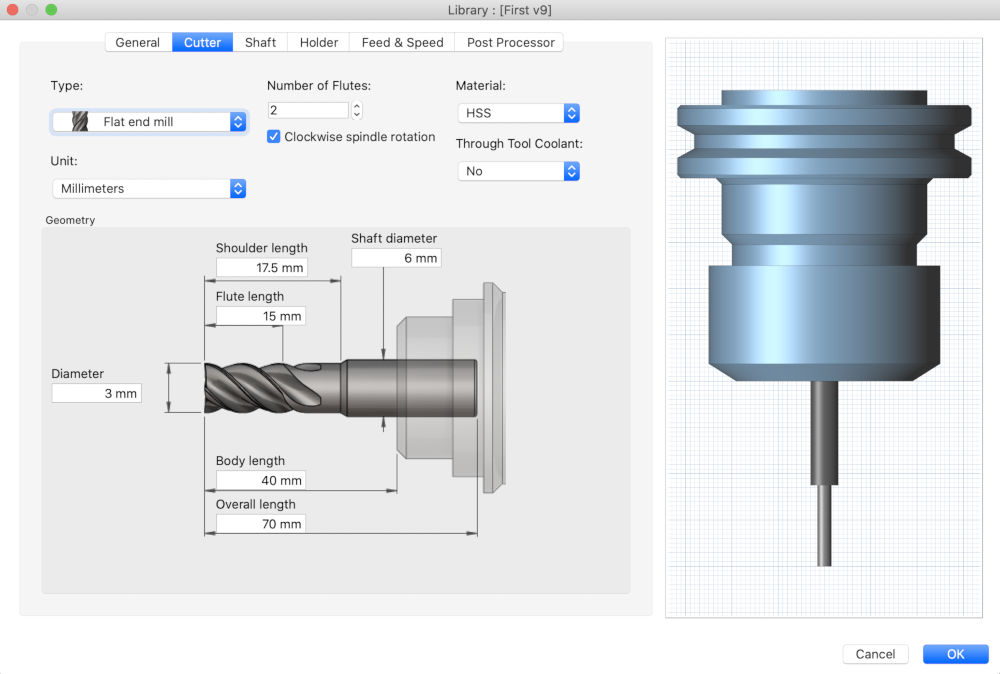
Then I entered the specifications of the endmill into Fusion 360.
- 2) In
Adaptive Clearing - Geomatry - Geomatry, The parts I wanted to cut was chosen in theMachining Boundary.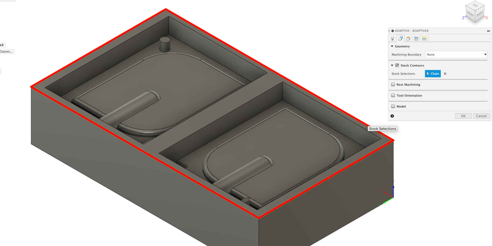
- 3) In
Adaptive Clearing - Passes - Passes, I set upMaximum Roughing Stepdown. Usually set the cut depth of endmill used to a value of endmill's diameter. So I adjusted the value of cut depth using the diameter of the endmill.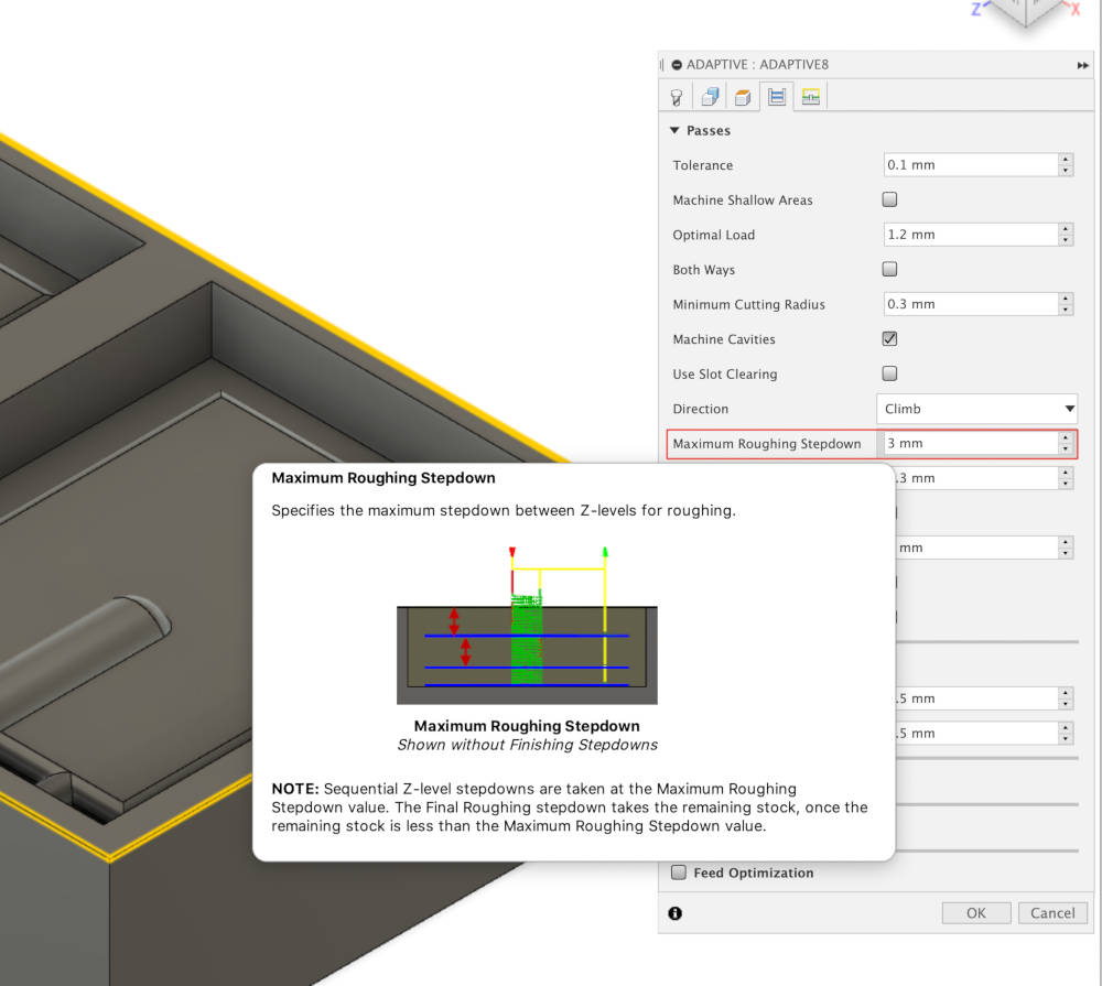
- 1) When making toolpath, the first thing to do is to choose the appropriate endmill for my design.
Then I entered the specifications of the endmill into Fusion 360.
- For the last trim, made another toolpath using
Scallopfunction in3DOption.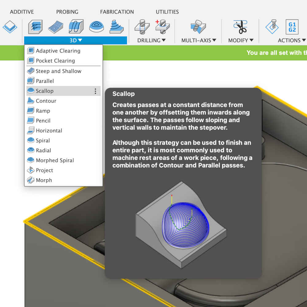
- 1) Followed the settings set above to set the corresponding part.
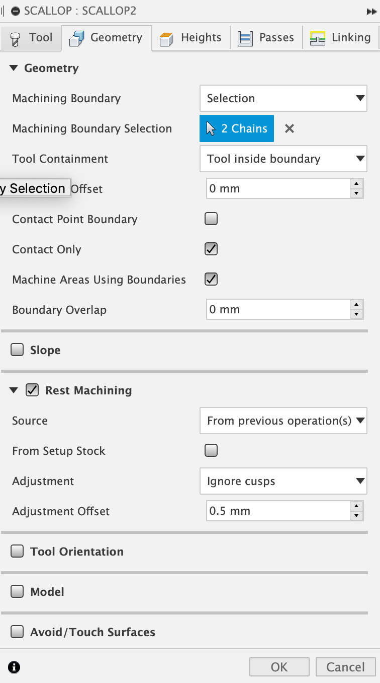
- 2) If you want to operate this toolpath by applying the sharpened part of the toolpath above, In
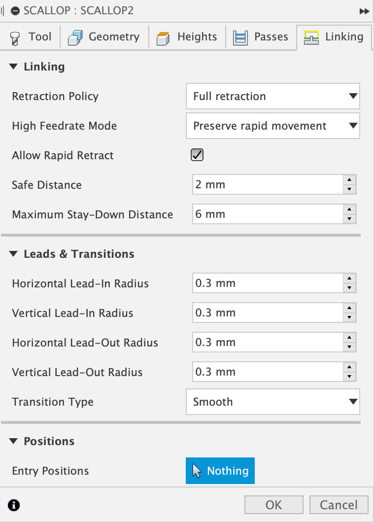
Scallop - Geomatry - Rest Mashining - Source, you can selectfrom previous operation(s). And it will reduce the machining time of toolpath. - 3) And for a smoother surface, In
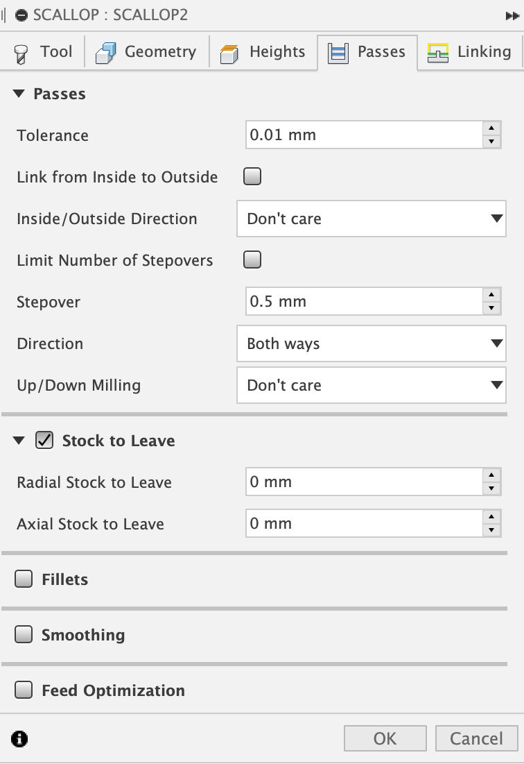
Scallop - Passes - Stock to Leave, Set the values ofRadial Stock to LeaveandAxial Stock to Leaveto zero. - 4) What you see below is the setting value of the scallop I chose.
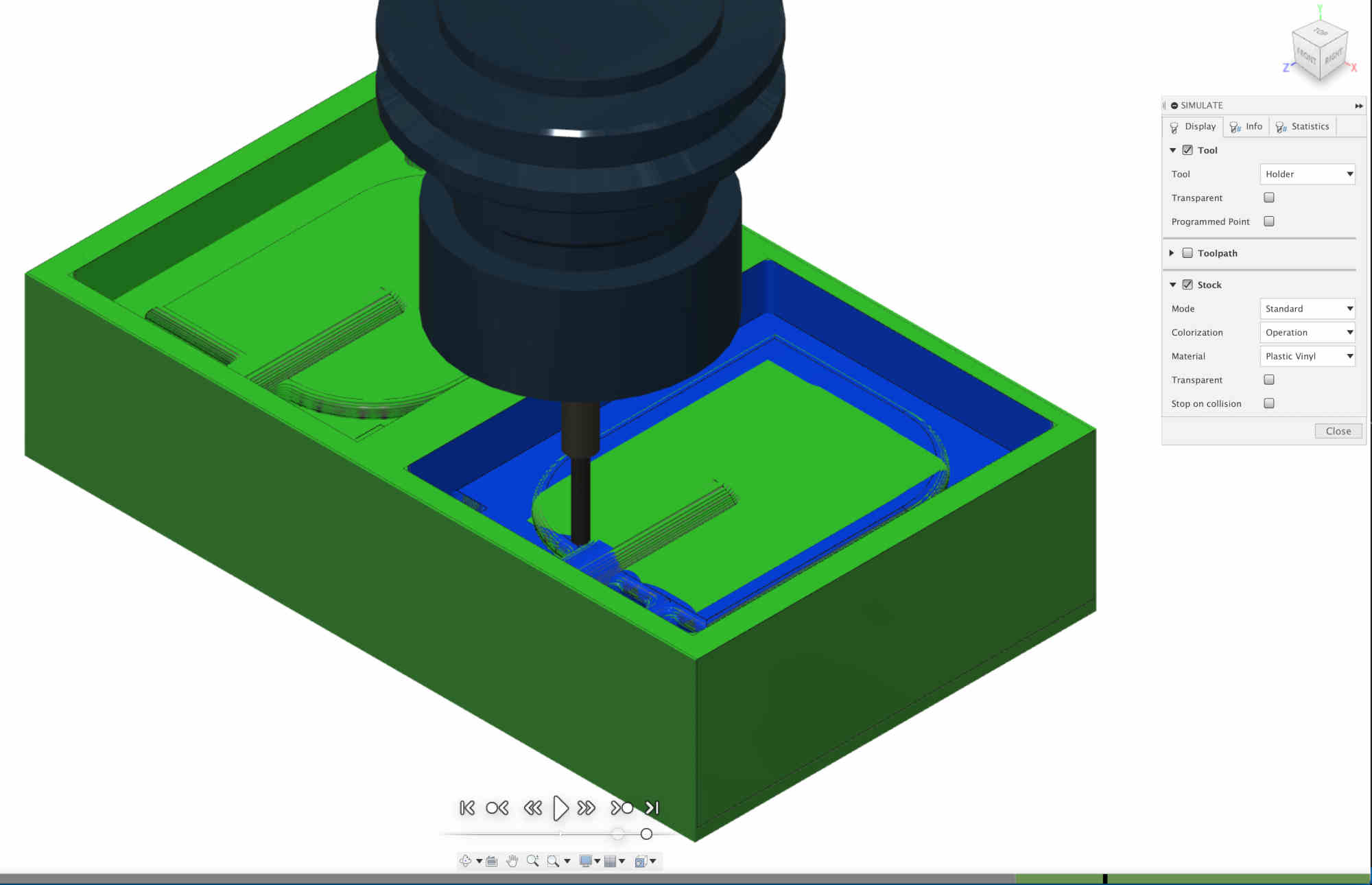
- In
the setup I made - Right Click - Simulation, Through the simulation, I could see if my work was in trouble or not.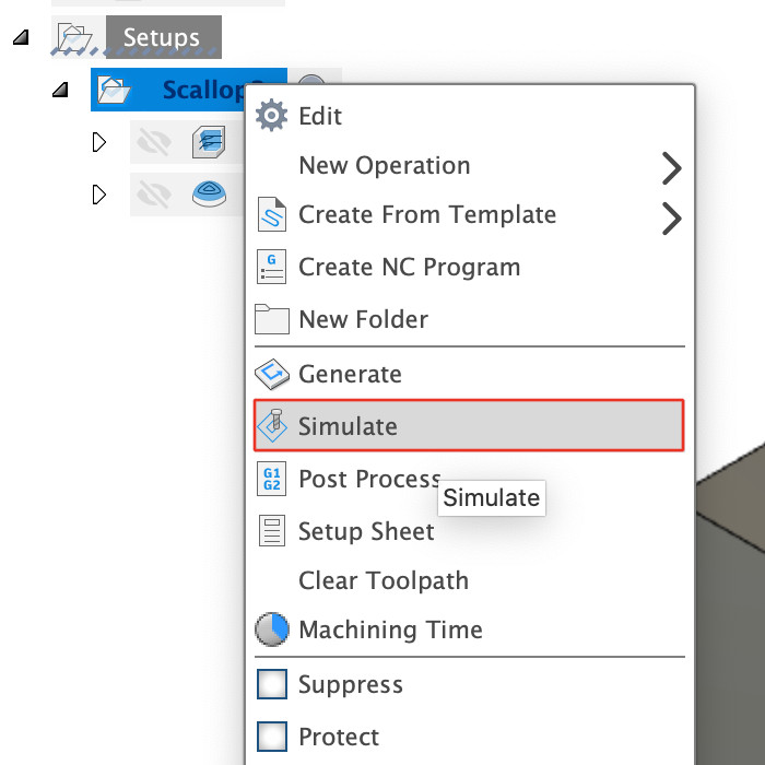
- In
the setup I made - Right Click - Machining Time, I was able to check the time of the milling machine.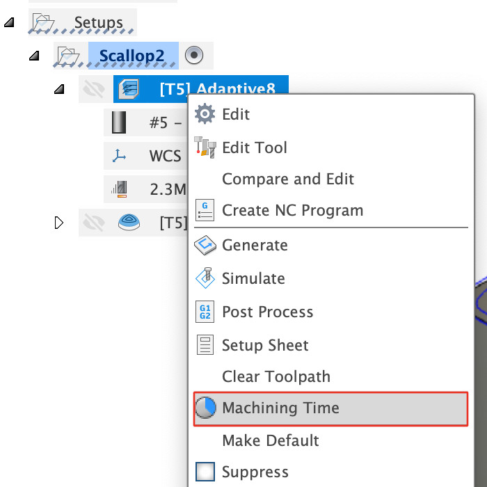

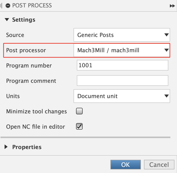
- In
the setup I made - Right Click - Post Process - Settings - Post Process, After selecting "Mach3Mill/Mach3mill", I was able to create a .tap extension file.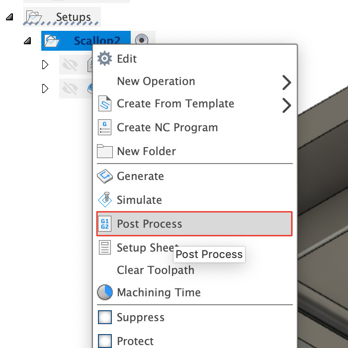
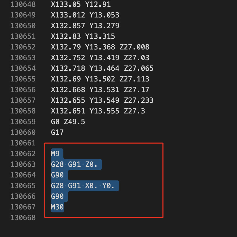
Since there was a problem with the Mach3Mill program used by our fab lab, we had to open the .tap extension file that was created and delete the code in the last red square. (The code in the red box is the G-code that goes to the origin when the milling is finished, but if you delete that part, the endmill is still in place even after the milling ends.)
1) I referred to this video.
2) First, make a plane that will be the top part.
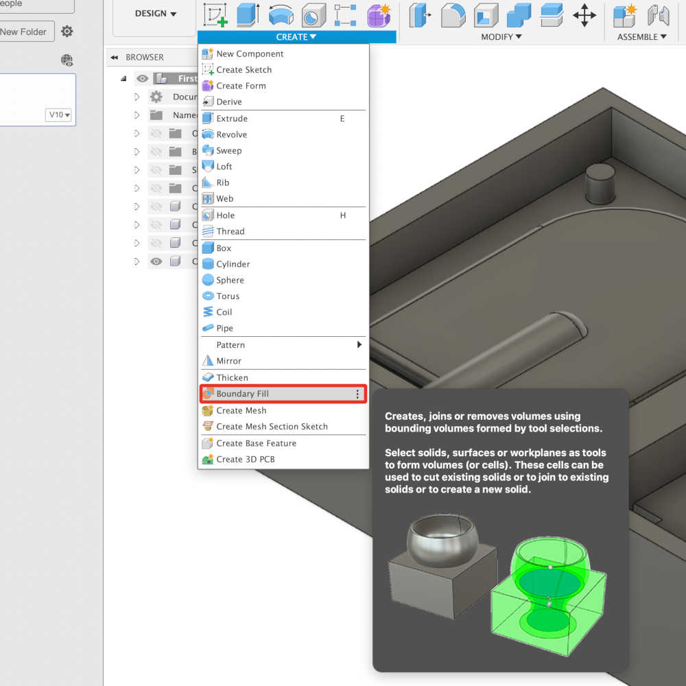
3) Use a function called Boundary Fill to select the space for the object inside.
4) Then go into the body's property made like that and check the volume.
5) Searching for that volume value in google shows it as a liter.
Milling
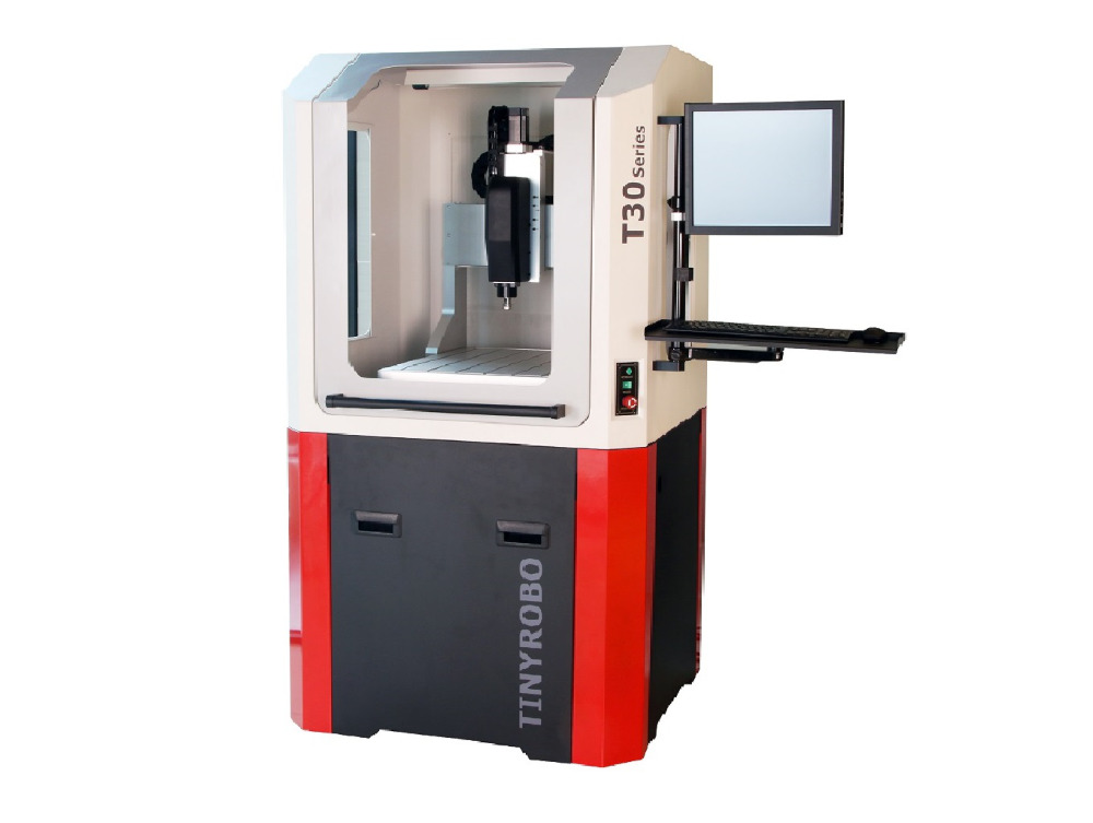
The CNC used for molding and casting in this week was TinyCNC-3035C. And it used the Mach3 CNC as its control program.
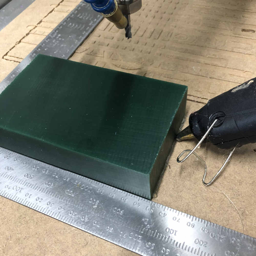
- After laying a plate on the CNC's workstation, I used a glue gun to attach the wax that I would use.
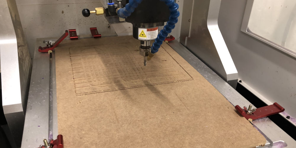
- And I've mounted the endmill I'm going to use on the CNC.
- And I turned on the Mach3 CNC program from the connected control computer.
- I opened the .tap extension file that I saved by
Import File.
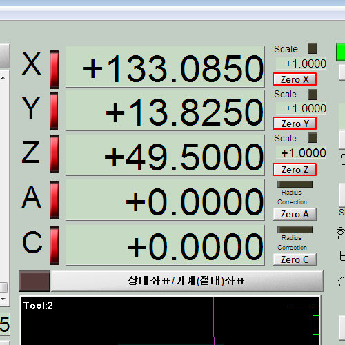
- set the origin of the x, y, and z axes.
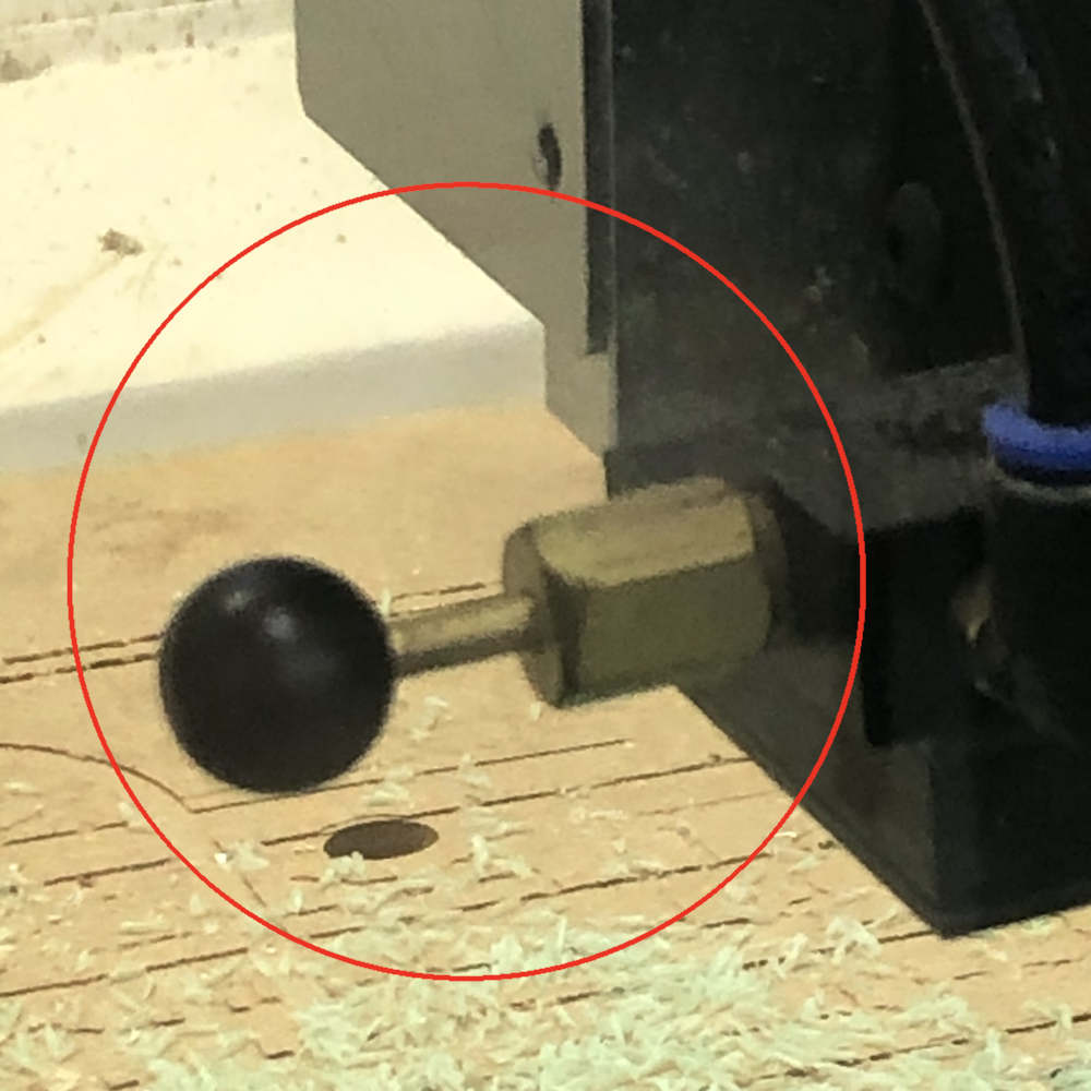
- After turning on the air compressor connected to the CNC, click the
Air_ONbutton to activate the air hose.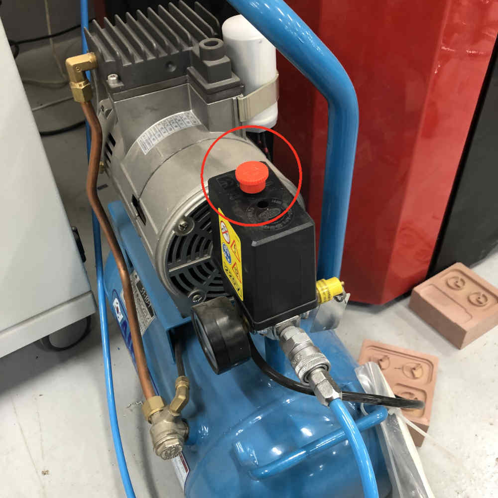

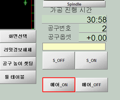
- And I started working by pressing the
Startbutton.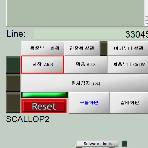
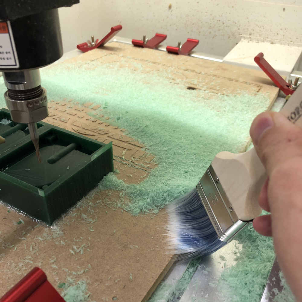
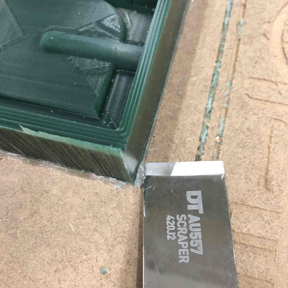
- After finishing the work, I used a brush to clean the chips, took out the plate, and removed the glue gun bond using a scraper.
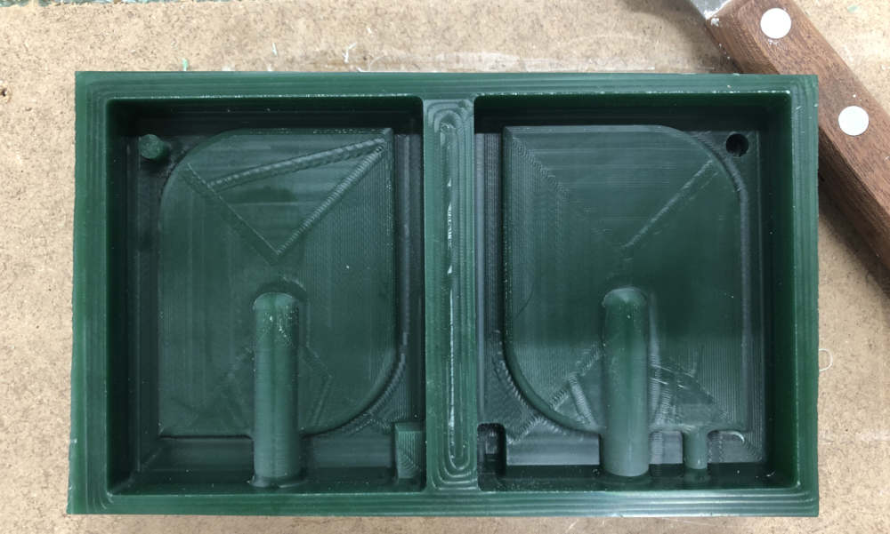
- Completed
When different kinds of endmill toolpaths were put into one file, the machine did not stop in time for endmill replacement.
So I waited by the side to finish the first task, then stopped the CNC and replaced the endmill.
Set the z-axis again and restart operation.
Then, the endmill moved unspinned, causing the endmill to break.
Depending on the type of endmill, the toolpath was divided, saved as a .tap extension file, and opened and operated in order.
The CNC does not stop when the work of one kind of endmill is finished.
Replacing the endmill in one operation takes the risk.
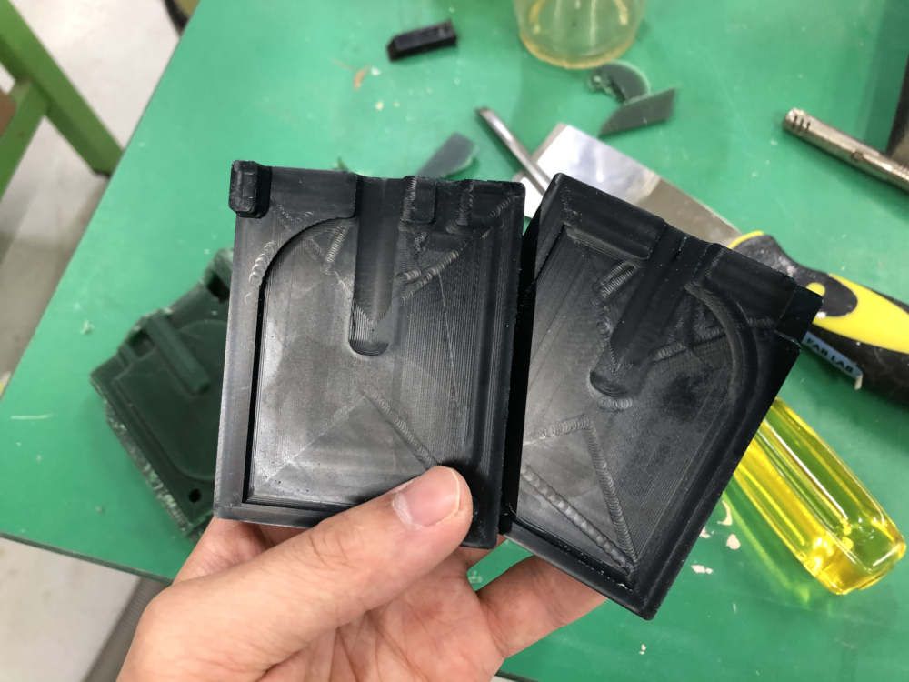
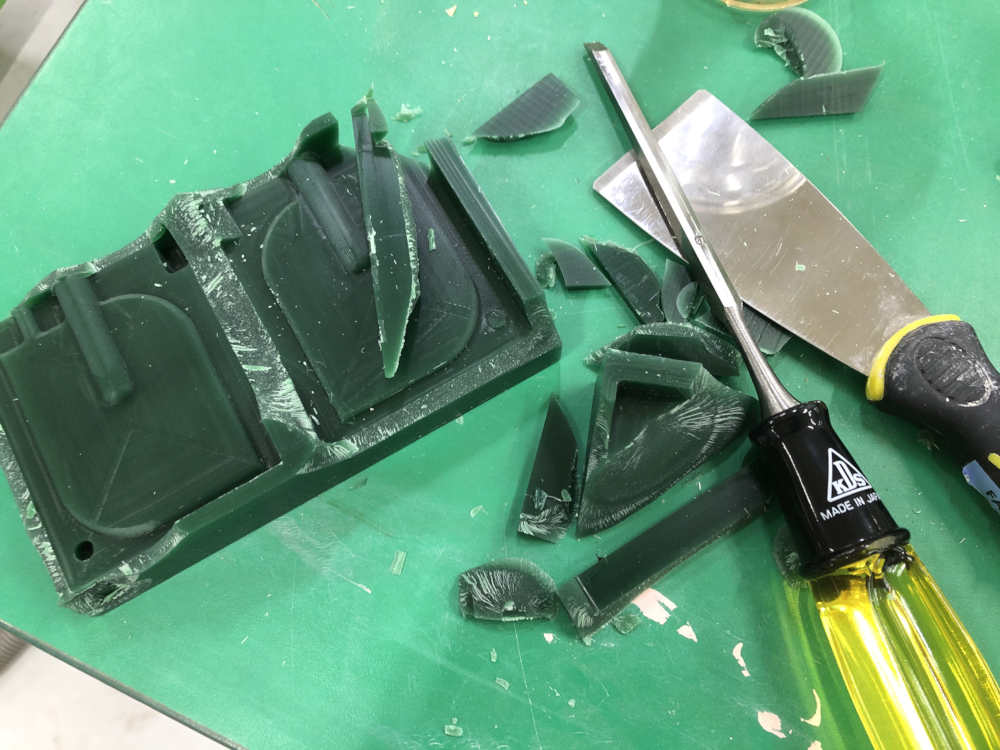
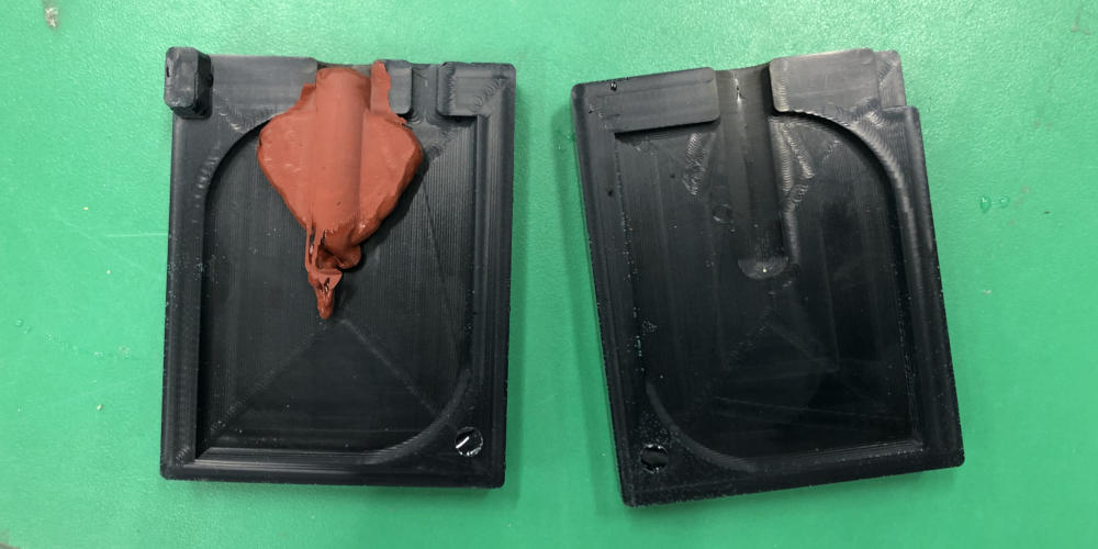
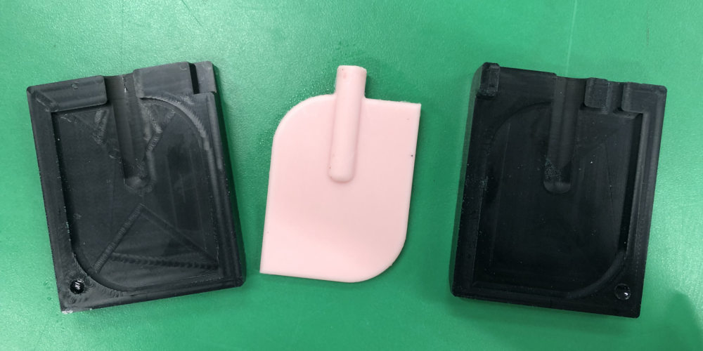
Molding
I thought I should use hard materials because it was a job to make a frame for casting objects.
The framework was created using Smooth-Cast 326 (Urethane).

After the pouring material in the wax had hardened, I realized that I had to use a flexible material for the pouring material in a solid frame.
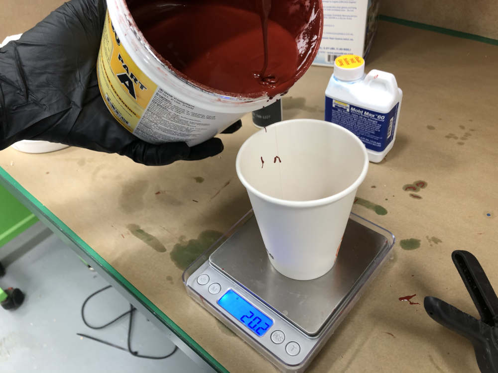
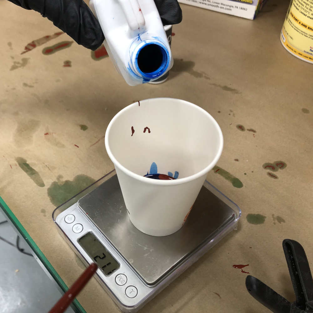
Casting
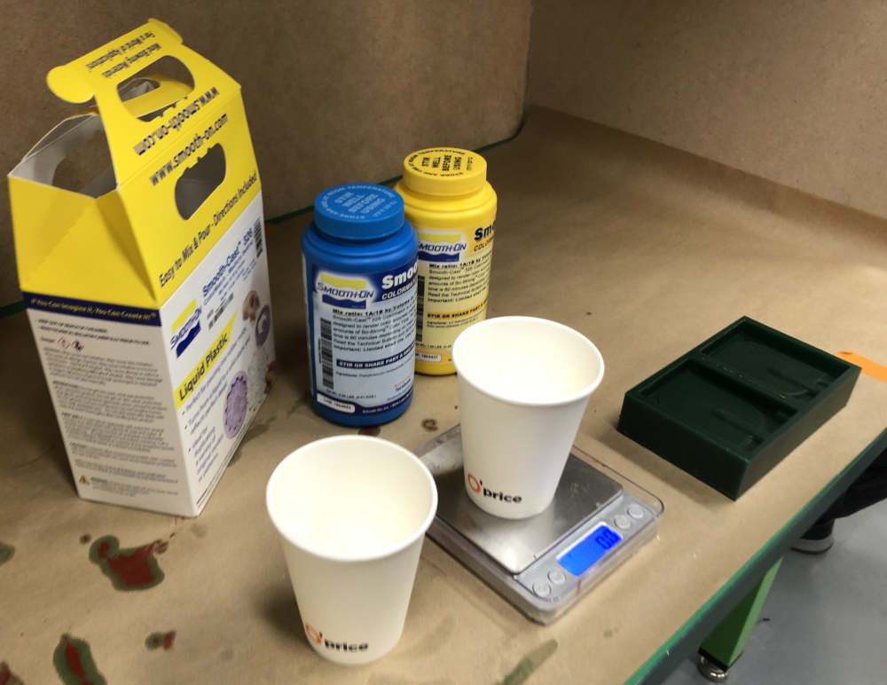
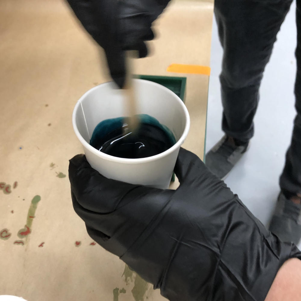
Mold Max 60 was chosen as the material for the object to be cast.
After mixing the materials of Mold Max 60, I used an vacuum chamber to remove the air bubbles.

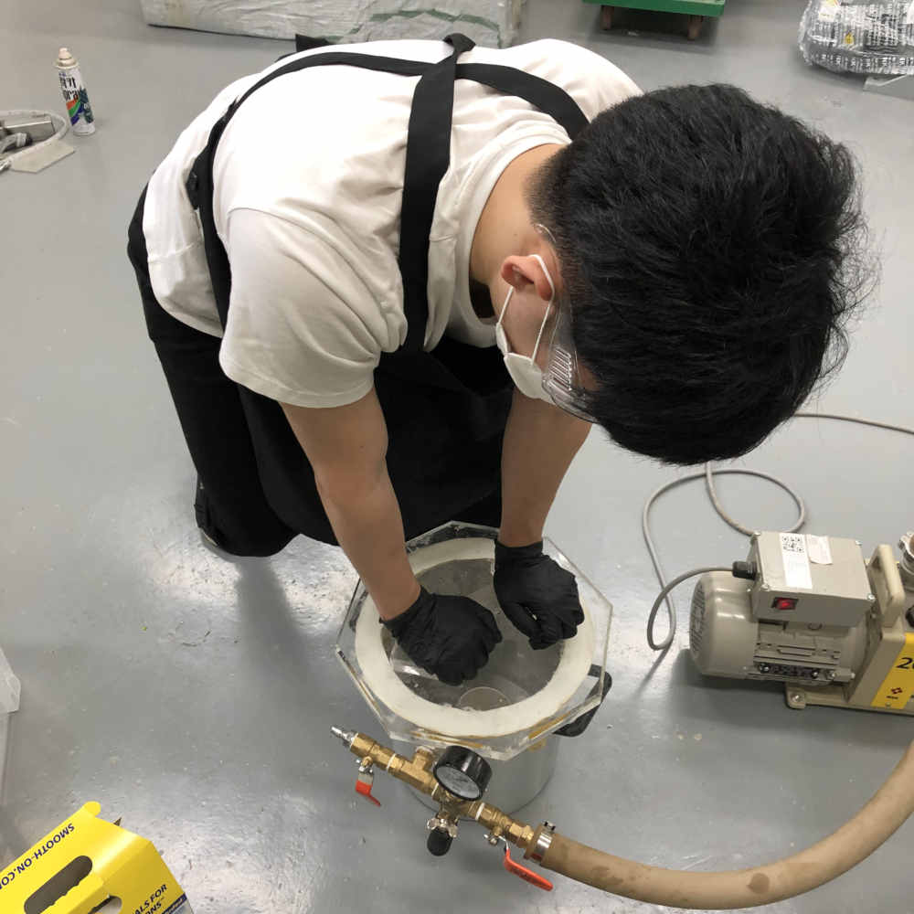
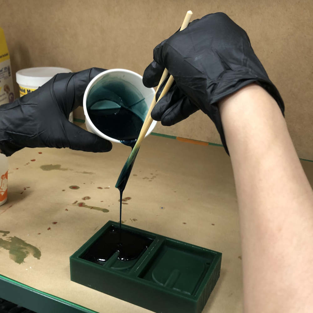
After using the vacuum chamber, I felt that the material did not flow better.
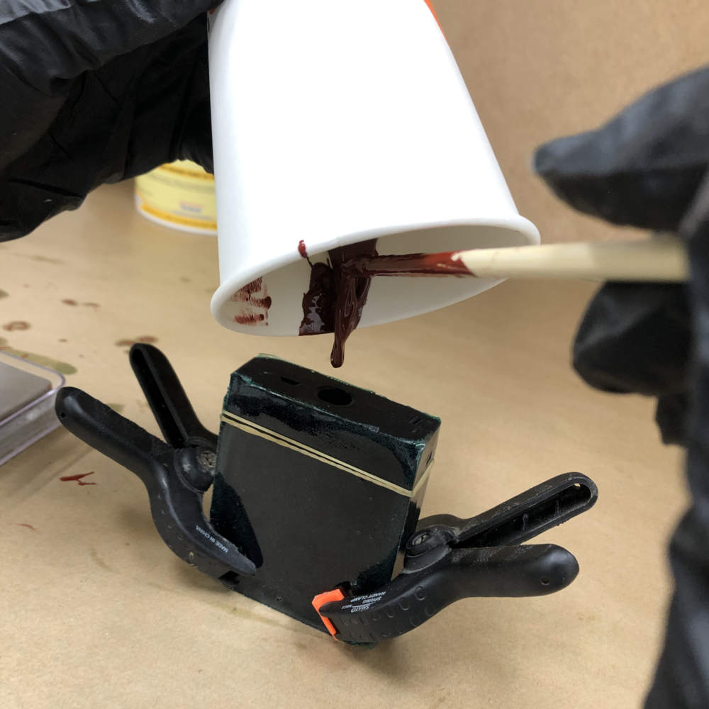
So when pouring material into the pouring hole, the material didn't go in well and failed casting.
I used the material(Smooth Sil 940) that flow better. (The material with lower viscosity were used.)

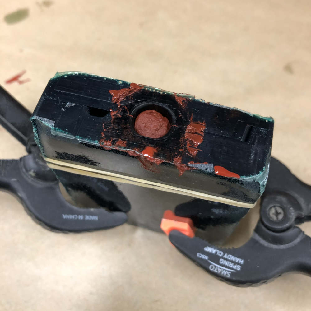
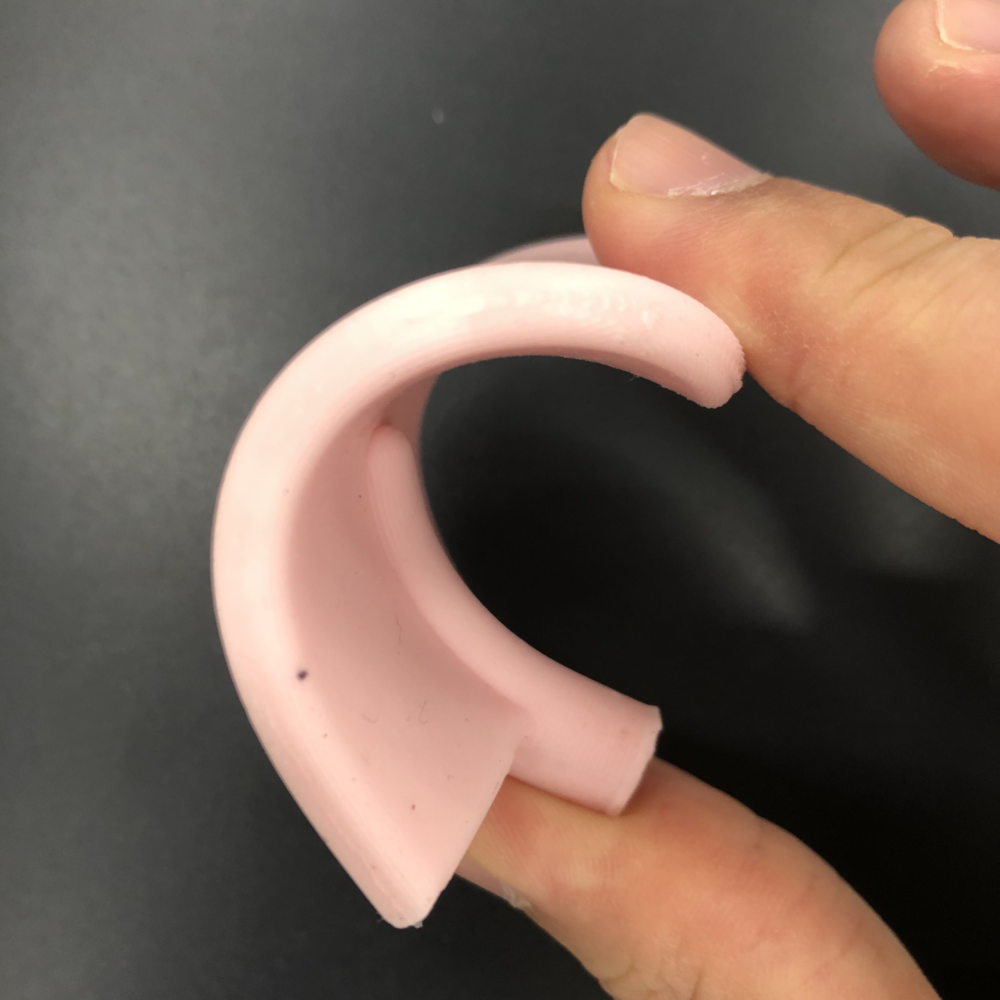
But the paddle was relatively thin, so it bent well. So I tried one more time using urethane material(Smooth-Cast 326).
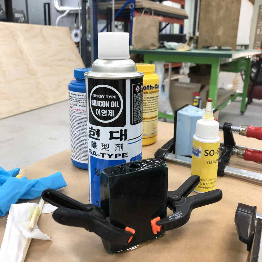
Because I used the same kind of material as my molding object, I spraied silicon oil on the molding object to act as a release agent.
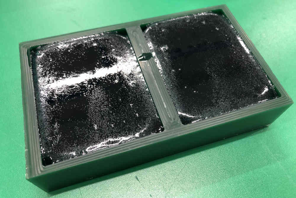
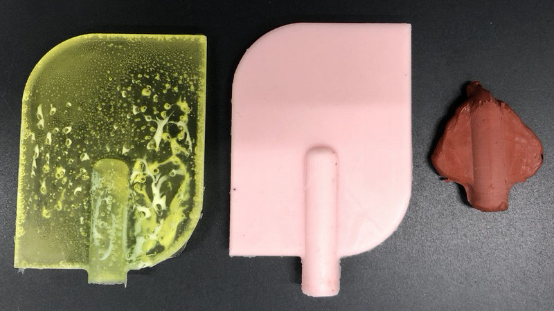
The leftmost one is the final result. Because it was sprayed with oil, it was easy to take out the casting product. However, Casting material swelled so quickly that there were many bubbles inside.
1) I learned about the properties of the material called viscosity, and that if its value is high it does not flow well and if it is low it flows better.
Reference sites related to viscosity
2) If you have enough time, apply a thin layer of release agent to get a smoother surface.