Test Sensors With Arduino UNO Boeard
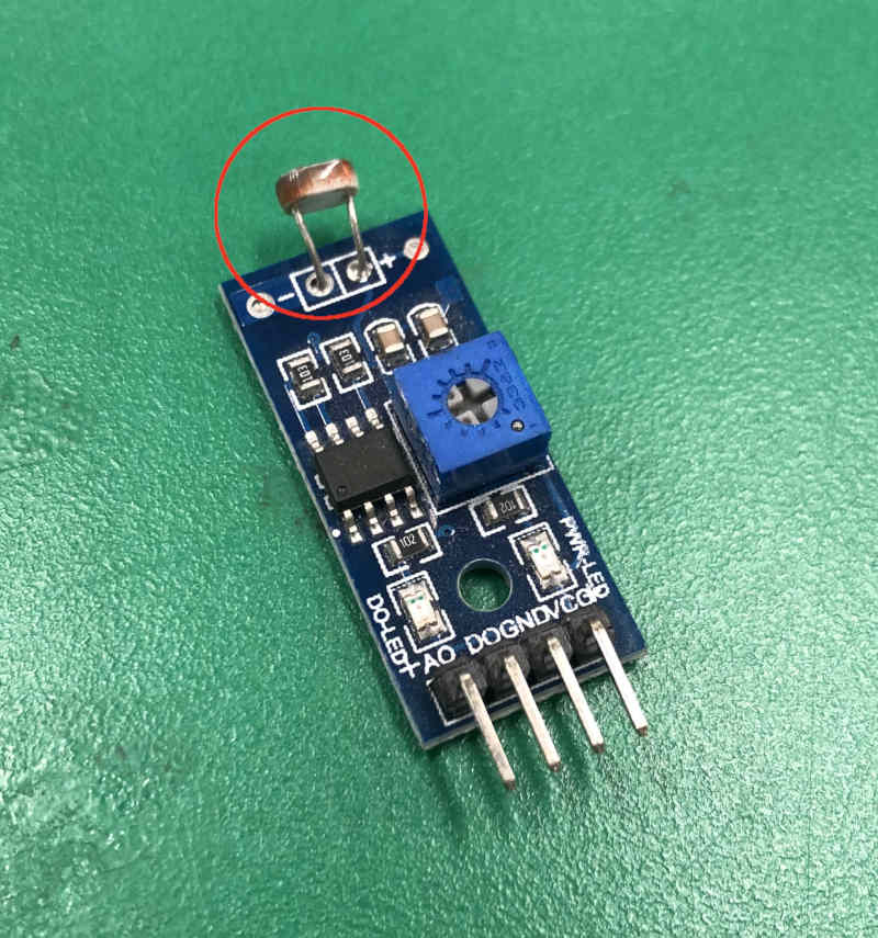
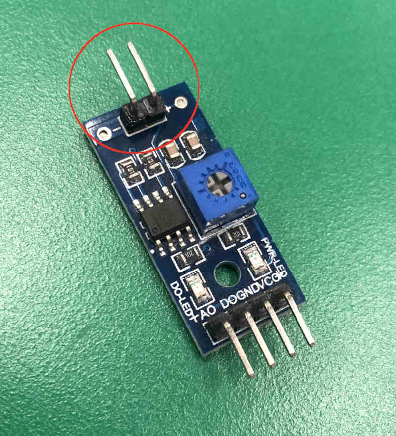
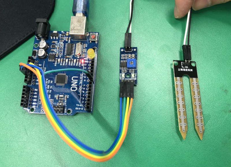
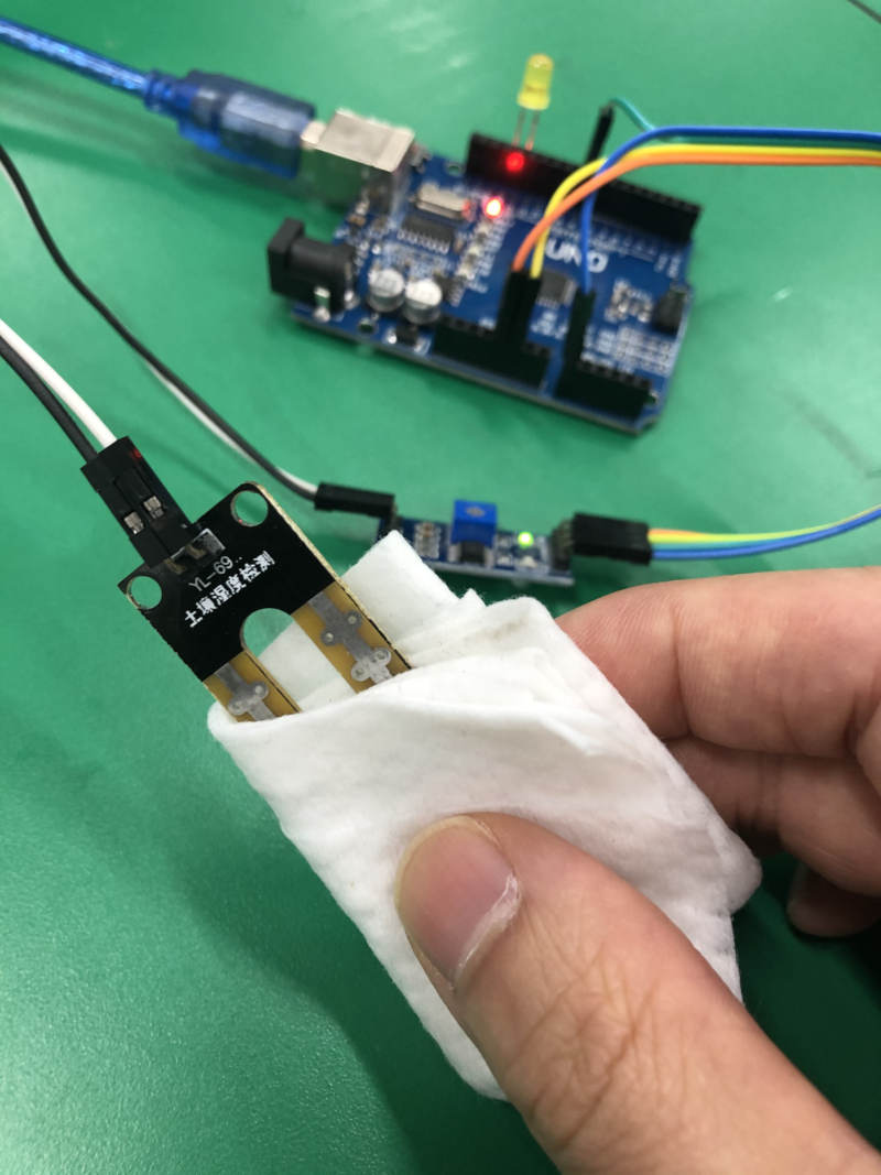
Soil Moisture Sensor (YL-69)
- Searched tutorial about Soil Moisture Sensor. (Tutorial Site)
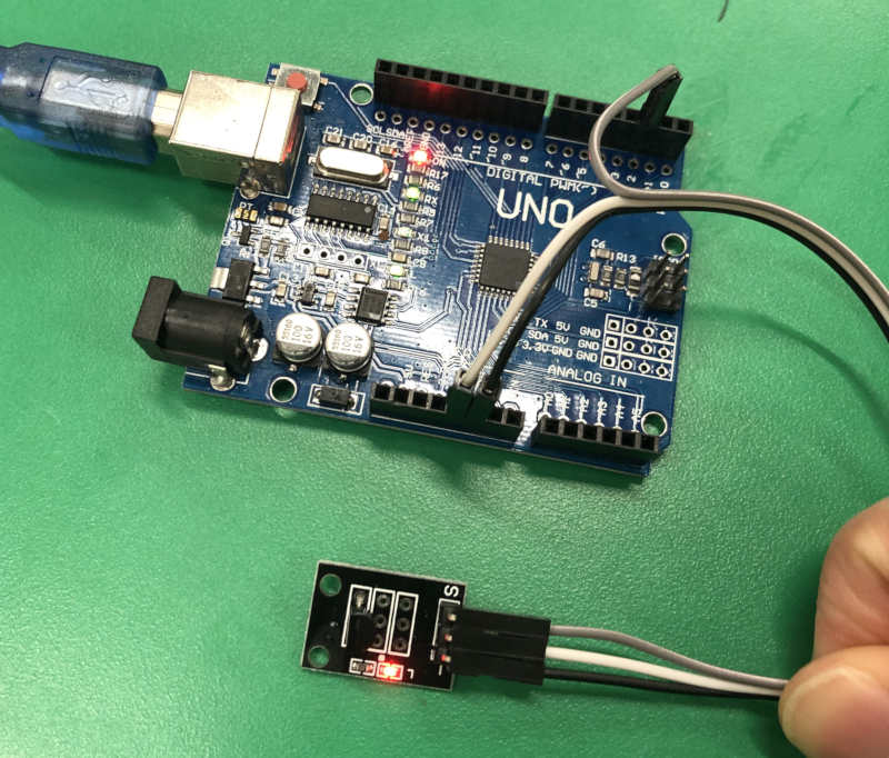
- Needed Soil Moisture Sensor Module. But There was the same module with different sensors. So Removed the sensor and attached the pin connector.
- And I tested the sensor along the tutorial by using Soil Moisture Sensor Module.
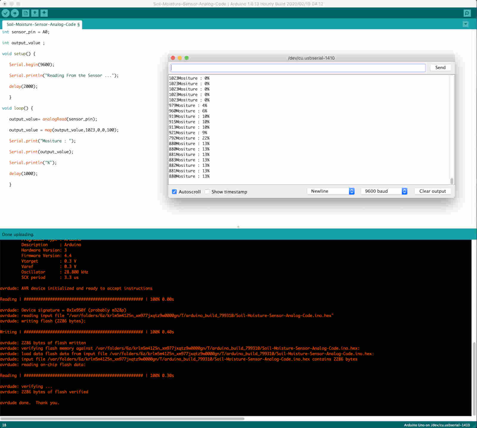
Learing
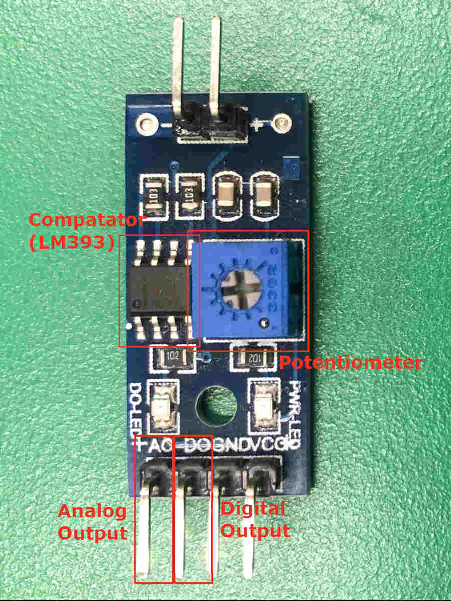
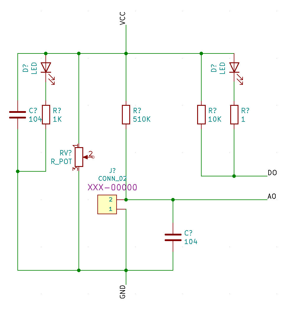
The module was divided into analog and digital output circuits.
The digital output circuit consists of comparator and potentiometer(variable resistance). (LM393 comparator datasheet)
What's the role of comparator?
The role of comparator is comparing the value of measured in potentiometer and sensor.
What's the role of potentiometer(variable resistance)?
It can be turned with a small screwdriver. This results in a different resistance value. As a result, the analog signal range of the sensor being measured can be adjusted.
Temperature Sensor (DS18B20)
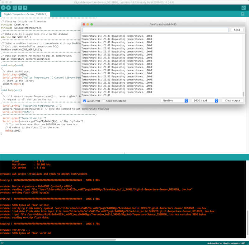
- This sensor is a logic sensor, and information about logic sensors was searched on Group Assignment Page. I hope you will refer to it.
- Likewise, Found a tutorial about it. The sensor I tested was a sensor board with the required resistor. (Tutorial Site)
- Downloaded two kinds of libraries because this sensor needed a library for the code.
- I tested it using the code in the tutorial.
ETC
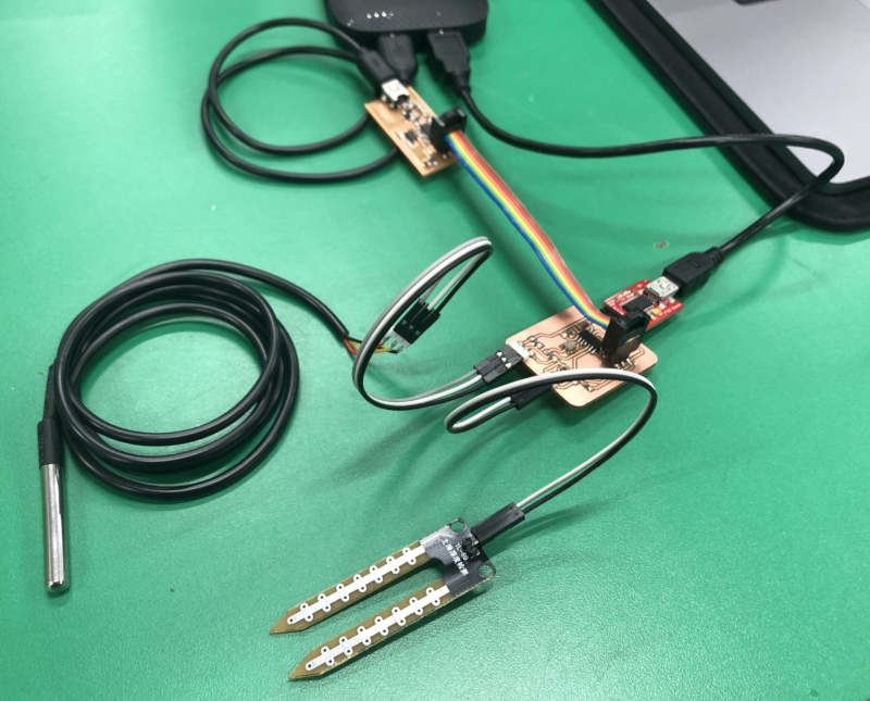
- Because I decided to put two sensors on my board,
- First connected the two sensors above to the Aduino board. And combined the code into one.
- The sensor both worked normally.
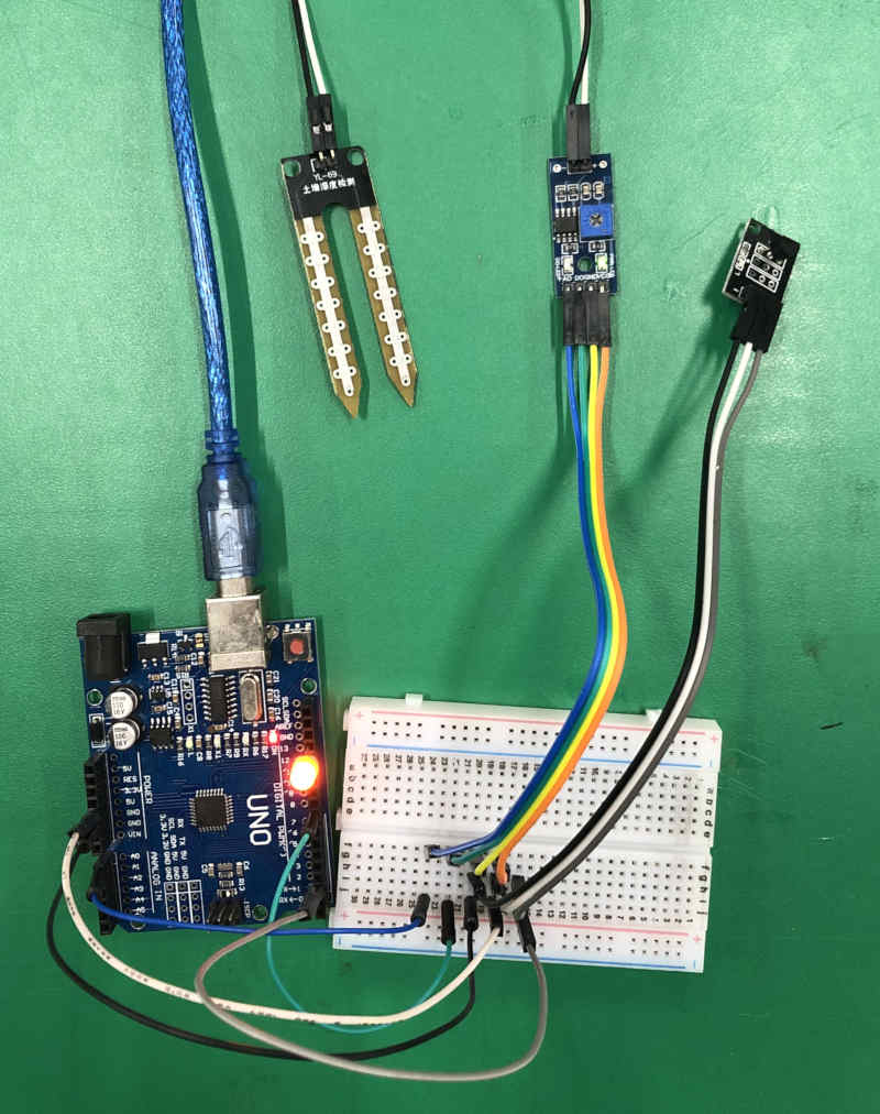
When I connected two sensors to the same vcc, The sensor reading values on the serial monitor has changed. Because the value of the voltage input to each sensor decreased. I wonder how this should be used to when I design and make boards.
Making Board (Desing, Milling And Soldering)
Design
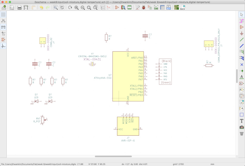
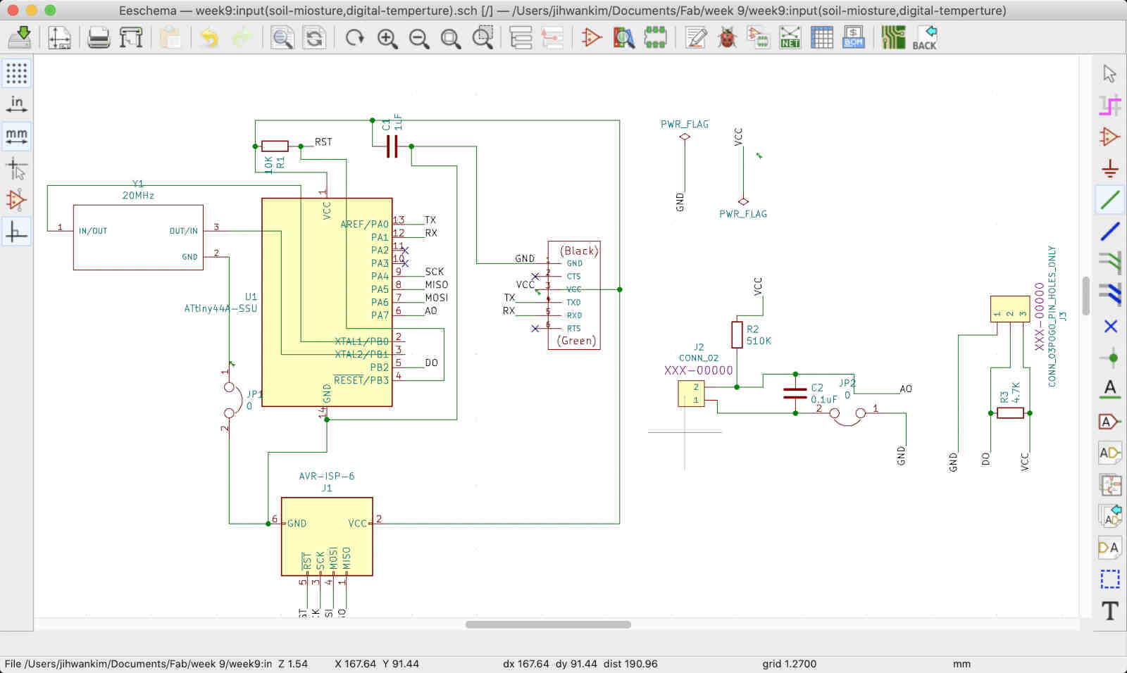
- In Kicad, Start to draw the schamatic circuit diagram.
 Problem
At first I tried to put both the analog and digital output circuits in the Soil Moisture Sensor Module on my board. It was too complicated.
 Solution
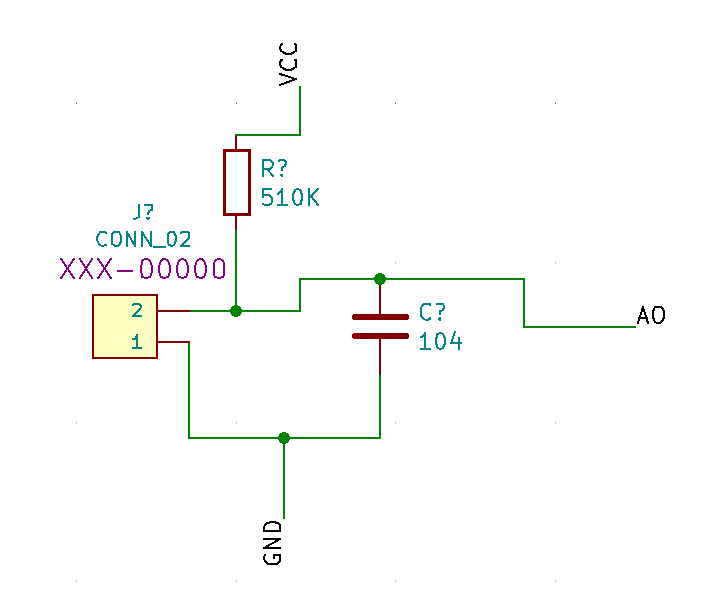
Instead of using a dedicated external Comparators with potentiometer, By converting analog information into digital code on the attiny board, we could do the same things it does. So removed that part from the circuit diagram I drew.
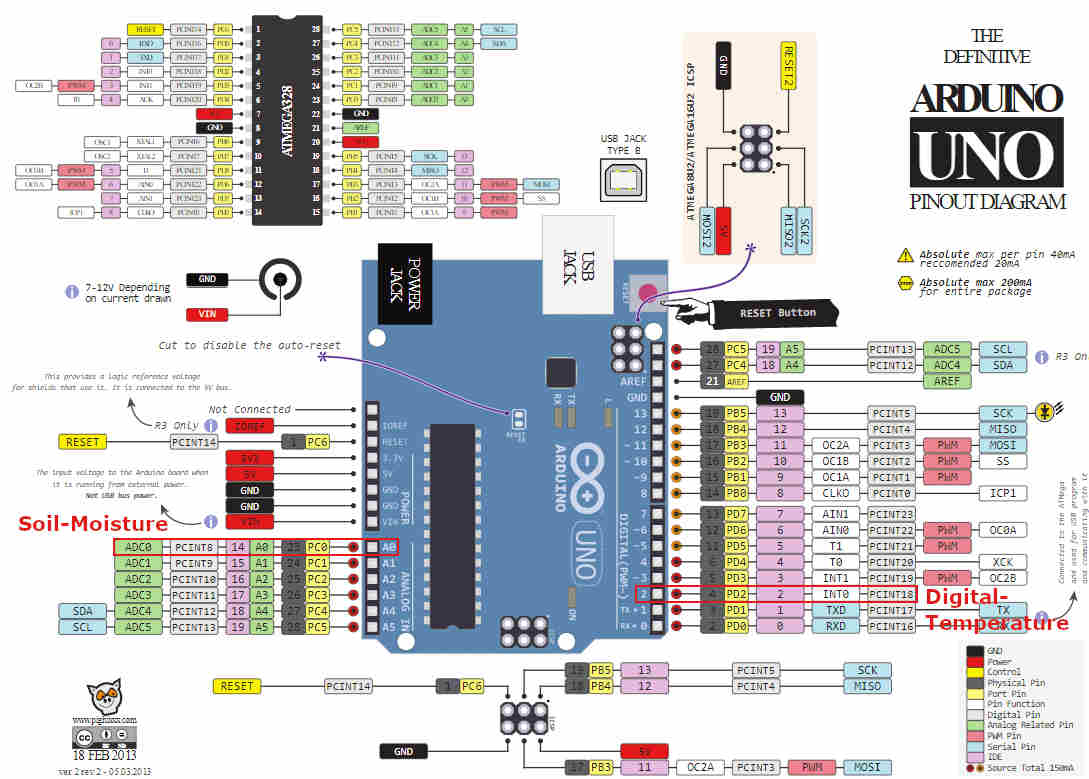
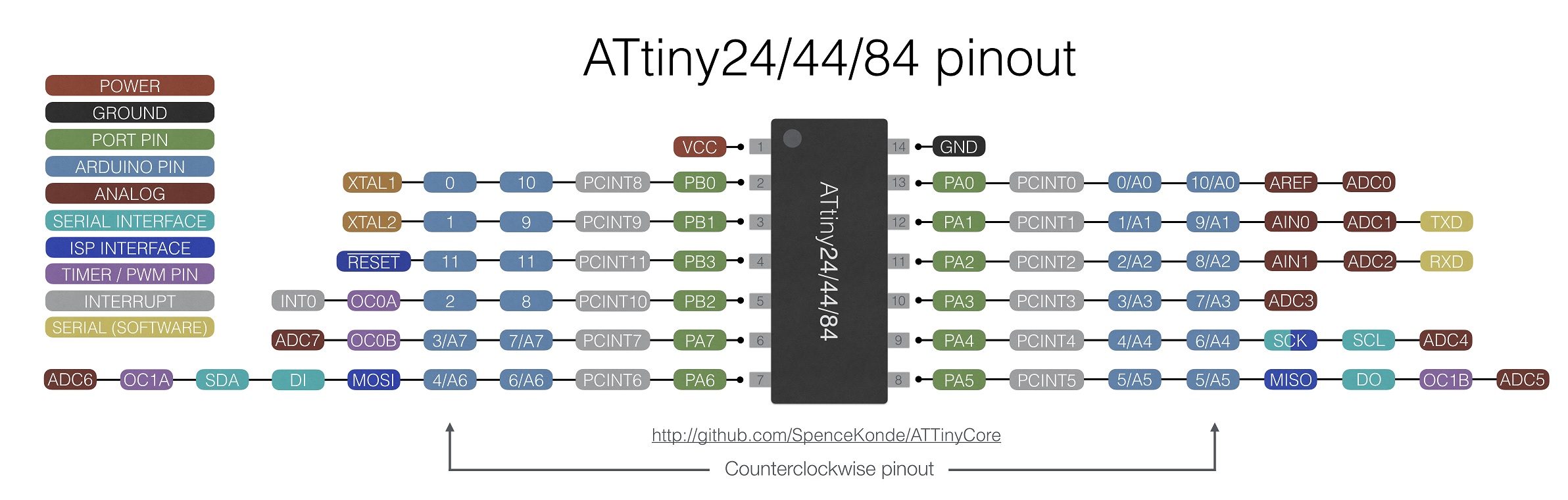
- I compared the aduino pinout and atiny44 pinout to match the pins suitable for the sensor. (Arduino UNO Pinout Site, ATtiy44 Pinout Site) The main purpose was to connect to the "ADC" pin to the analogue sensor, the soil moisture sensor.
Arduino UNO pinout
ATtiny44 pinout
 Learning
ADC means "Analog to Digital Converter". So I will be able to convert the analog signal I receive from the sensor into a digital signal later. (INPUT)
In addition, "PWM" means "Pulse-Width Modulation". It is a method for generating an analog signal using a digital source. Namely, It is used to send out analog signals. (OUTPUT) And it can be used with resistors or capacital to produce more refined values.
- Then I finished drawing schamatic circuits safely and moved on to PCB design.
- Before connecting components, printed a pcb footprint to compare it to the actual size of the component.
In the week 8, I compared the size after connecting all the components, but realized that doing it before connecting was more effective and time-saving.
 Problem
The resonator we have had GND in the middle, but the resonator in the footprint had GND on the side.
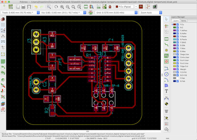
- This is my completed circuit diagram.
Schamatic
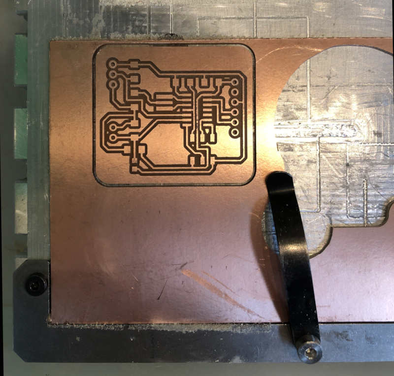
PCB
Milling And Soldering
- The milling process was really smooth. It's really an easy process to extract from a Kicad to a .gbr file and cut a copper board with Bantam software.
- But soldering was not.
- First, soldering iron's tip burned so black that there were many difficulties in soldering.
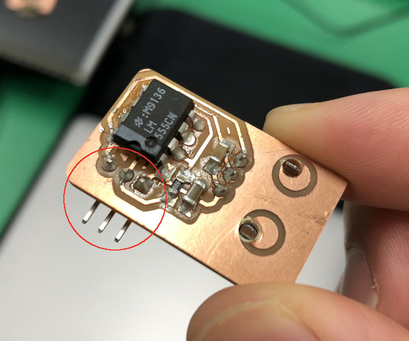
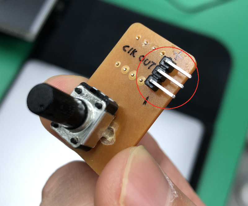
- Secondly, I planned to use L shape pin connectors, but the holes for L shape pin connectors did not seem suitable for the copper plate. The lead would not stick to any other part except copper and it seemed impossible to put the lead through a hole in the joint.
- And After much effort I chose to bend one side of straight shape pin connectors and solder it.
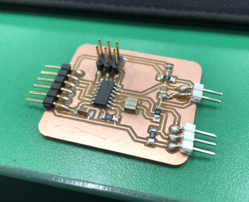
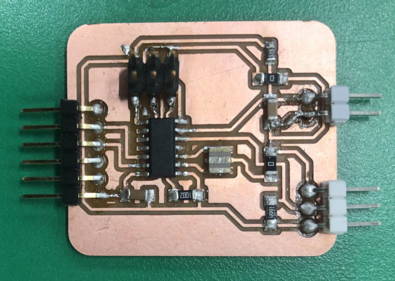
- Later, My instructor gave me a good idea. It is to attach the component to the bottom side.
Programming
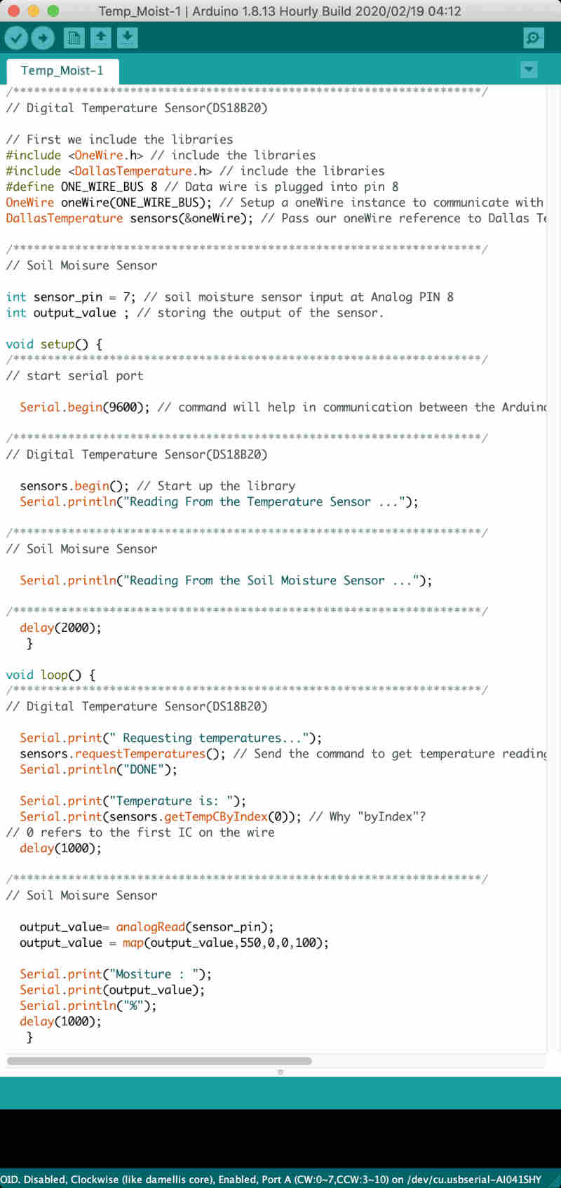
- The first attempt was to upload code after modify only pin informations in the code consisting of two types of sensor codes that were last tested on the Arduino board.
 Problem
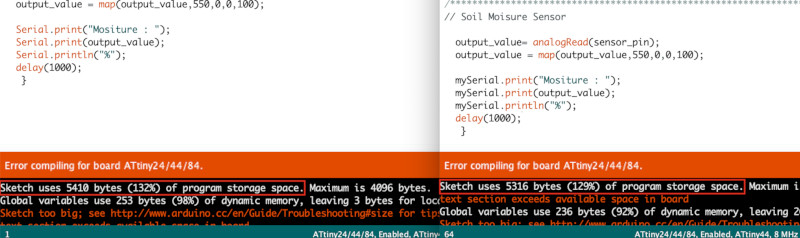
The capacity of the code was larger than the capacity of the ATtiny44, so it could not be uploaded.
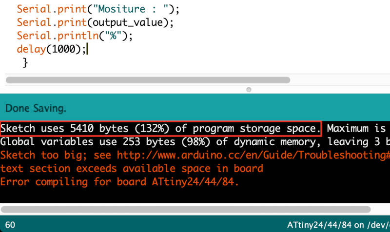
I should have checked the capacity of the code in advance in the Aduino test.
SolutionI decided to reduce serial code, which takes up a lot of capacity, Because Serial code accounts for a large portion. So I searched and downloaded the "send only software serial library". Than I used this code. (Reference site)
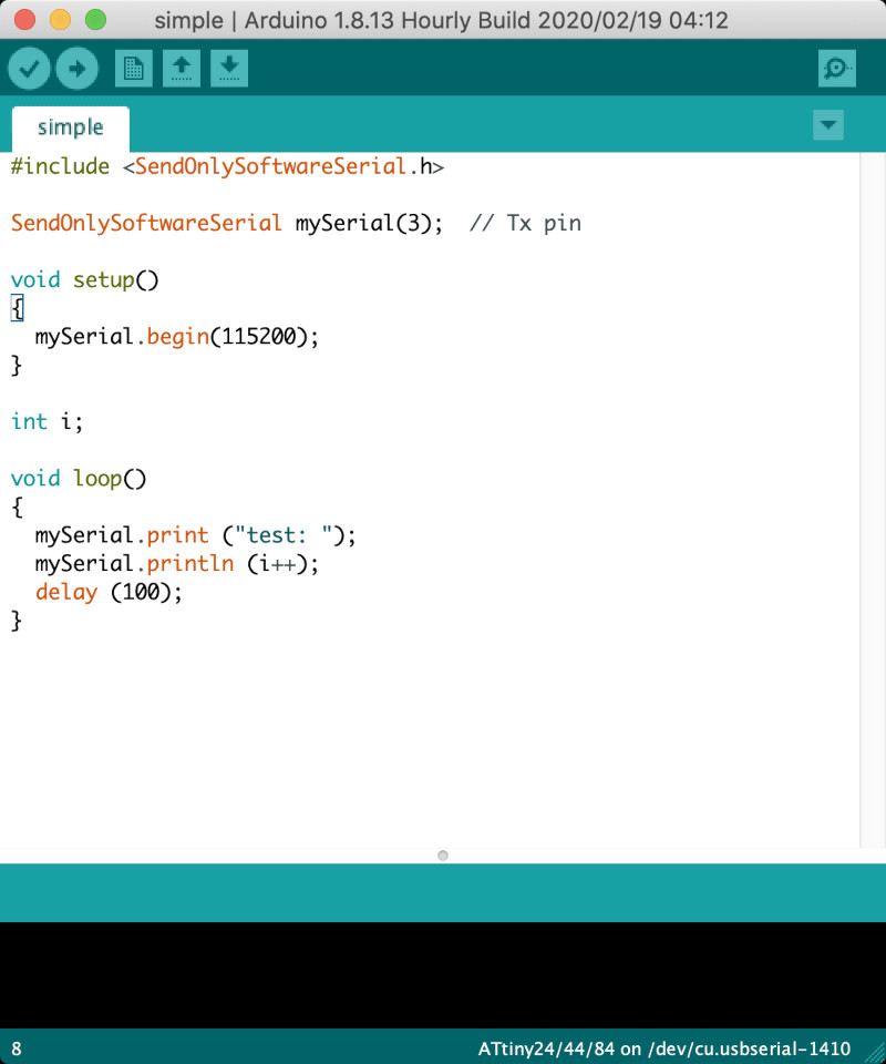
When I changed the serial code, the capacity of the code was reduced about 100 bytes.
 Learning
First, I learned about Tx, Rx. Tx (T=Transmit) is the same as the mouth and Rx(R=Receive) is the same as the ear.
Second, Kinds of serials include hardware serial and software serial, and software serial libraries for different purposes.
Hardware Serial - It's in the MCU. Library does not need, This "Serial.begin, Serial.print, Serial.println" that we usually use is hardware serial.
Software Serial - Downloading library is required, Software Serial library codes required.
Software Serial Library - Be created for specific purposes of Software Serial.
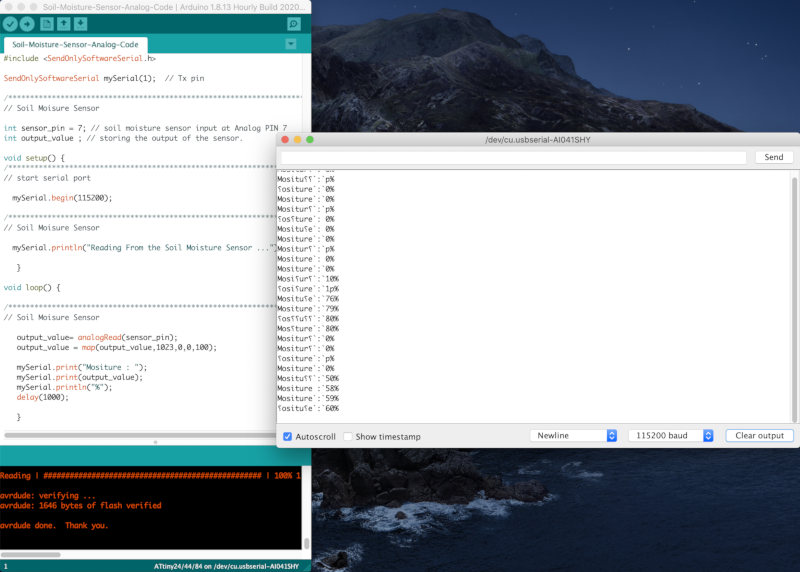
- Then I used software serial library to fix the code and first I tried only one sensor, soil Moisture sensor.
- It worked.
- Also I tried the temperature sensor's code separately.
- But even though I only fixed the serial code, it still did not succeed because the capacity of the code exceeded the capacity of memory.
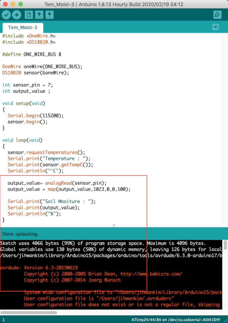
- So I found a temperature sensor code with less capacity and combined it with the moisture code. (Reference site)
- The code accounted for 99 percent of the memory capacity and I was able to upload it by a hair's breadth.
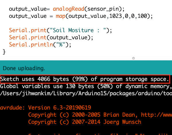
- Here are the code & video
Temperature and Moisture Code
                #include <OneWire.h>
                #include <DS18B20.h>

                #define ONE_WIRE_BUS 8

                OneWire oneWire(ONE_WIRE_BUS);
                DS18B20 sensor(&oneWire);

                int sensor_pin = 7;
                int output_value ;

                void setup(void)
                {
                   Serial.begin(115200);
                   sensor.begin();
                }

                void loop(void)
                {
                   sensor.requestTemperatures();
                   Serial.print("Temperature : ");
                   Serial.print(sensor.getTempC());
                   Serial.println("°C");

                   output_value= analogRead(sensor_pin);
                   output_value = map(output_value,1023,0,0,100);

                   Serial.print("Soil Mositure : ");
                   Serial.print(output_value);
                   Serial.println("%");
                }
Video