Make Something Big
Decided to make a final project prototype out of something big.
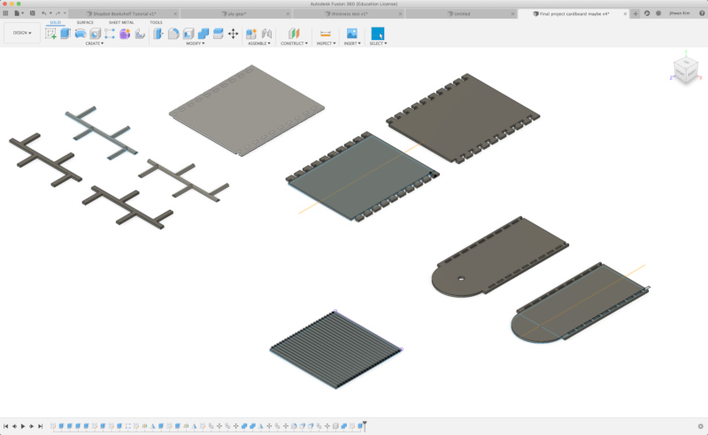
Design
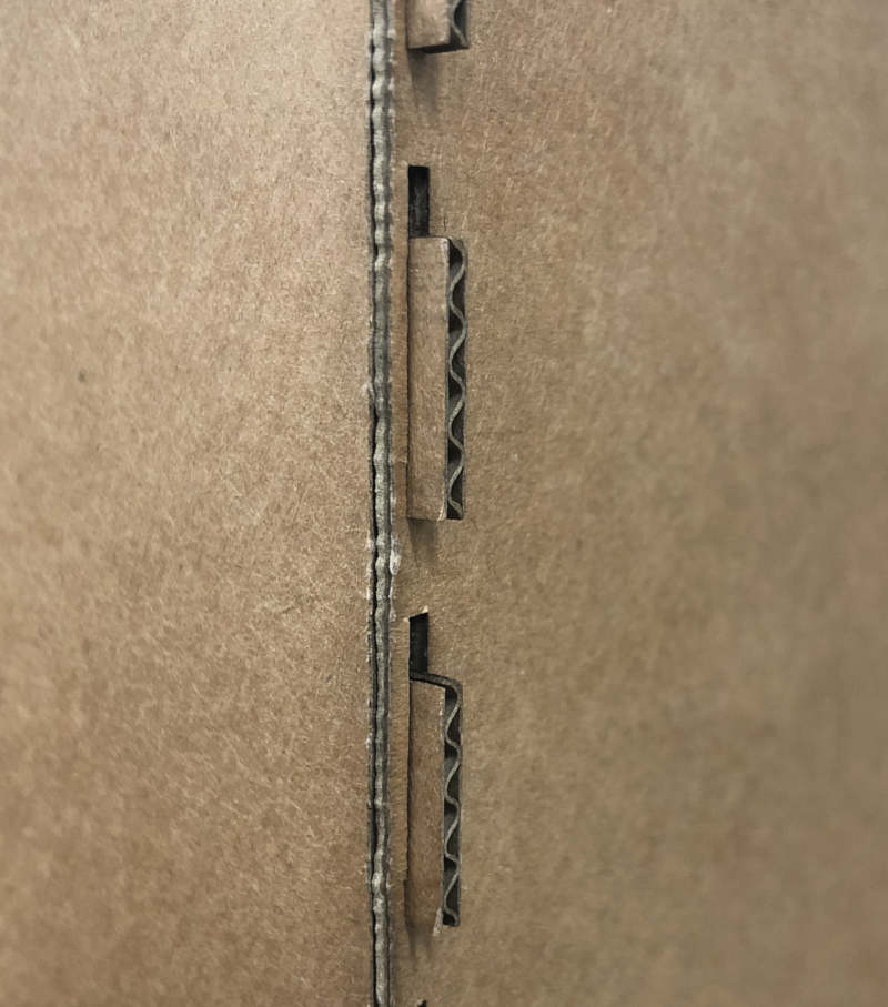
Designed parametric with Fusion360. First design was Cardboard version. In draft, Joint was simple box joint but changed to hook joint to make it stronger.
Cardboard in laser cutter (K2)
Good
1) Easy and quick mothod to see the full dimensions of the design.
2) Not difficult to combine without the need for clearance.
Bad
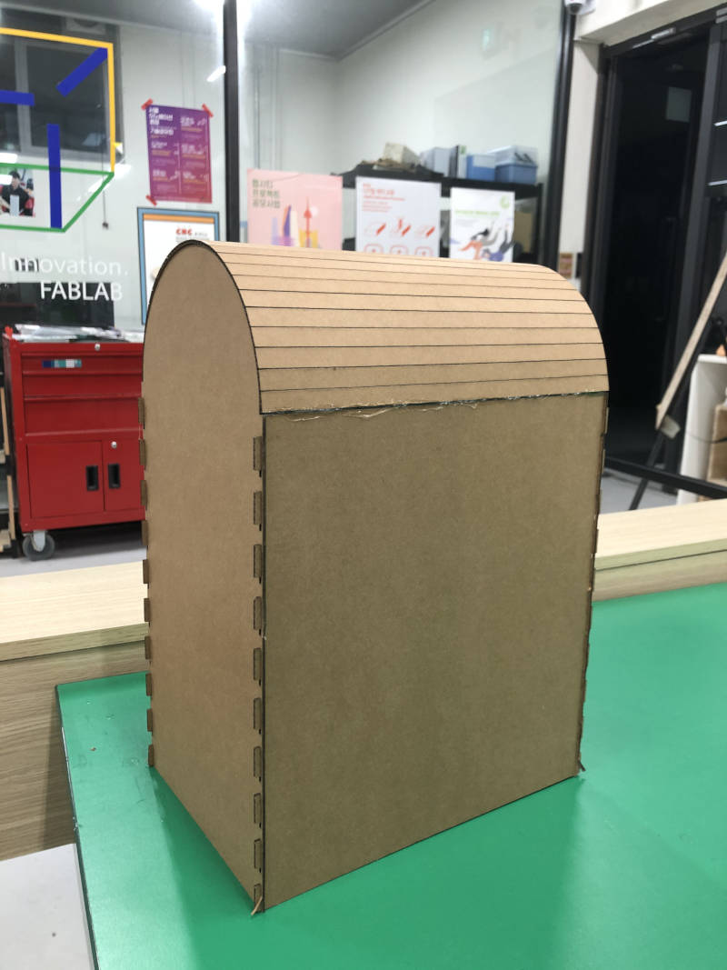
1) Not suitable for testing gears. Because the thickness of the material was 1.6mm.
2) I had to use a glue gun to combine the kerfing part because I didn't put a joint on the saw kerfing part.
Plywood 4mm in laser cutter (Trotec speedy 100)
In Design
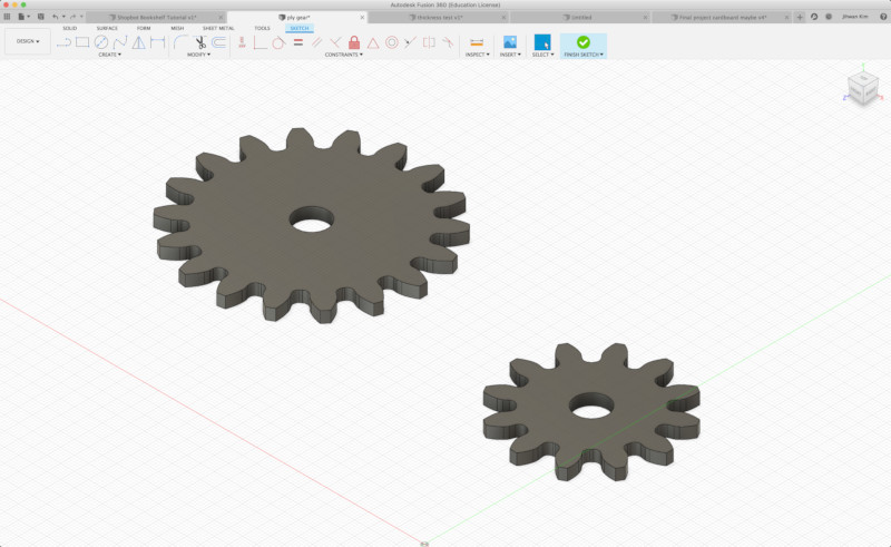
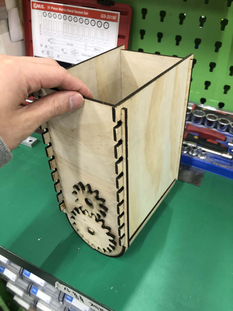
1) I was able to include the gear in design. Gears was designed through FM GEARS in fusion by borrowing a computer from a friend who uses Windows.
2) The rest of the design was carried out only by changing parameter values in the cardboard design. My parametric design was not perfect, so I could find some flaws in areas where parametric wasn't applied.
In Result
1) Multiple joints were interlocked tightly to the connections, so more clearance was needed.
2) The different sizes of gears had to be slightly spaced to make a good rotation.
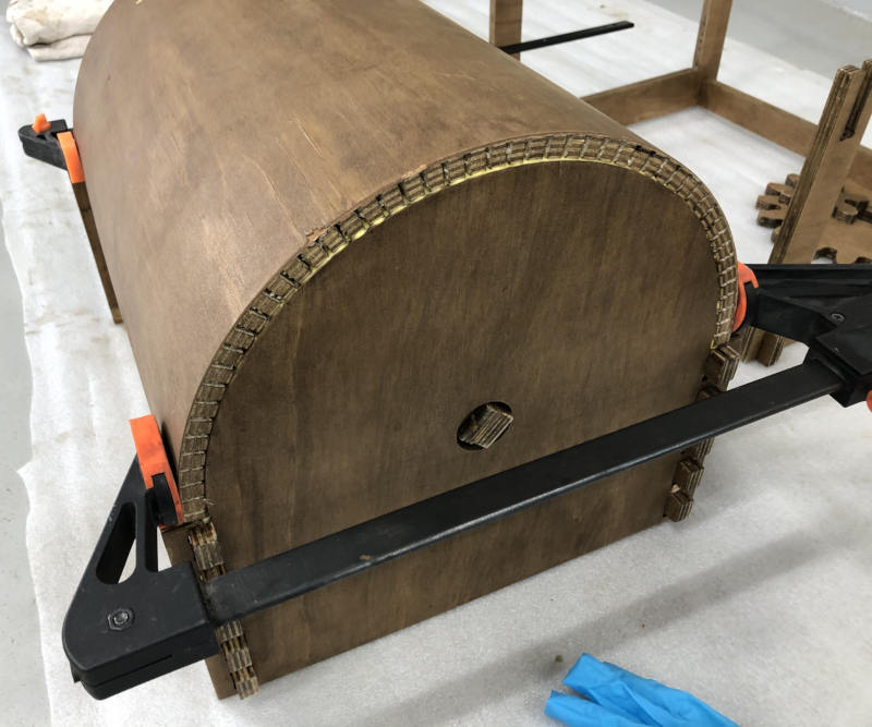
3) Unlike cardboards, some of the kerfing parts were broken because of lack of flexibility.
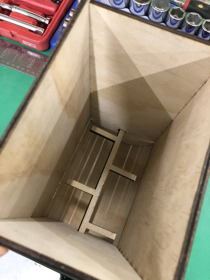
Joint & Saw kerfing Test in CNC
Based on the results made by card board design, Tested joint and saw kerfing using 6 mm endmill.
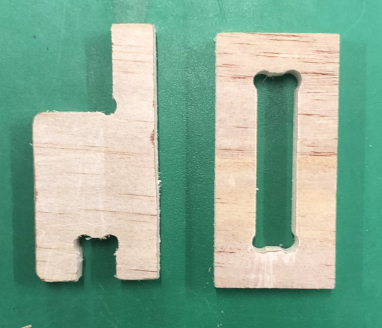
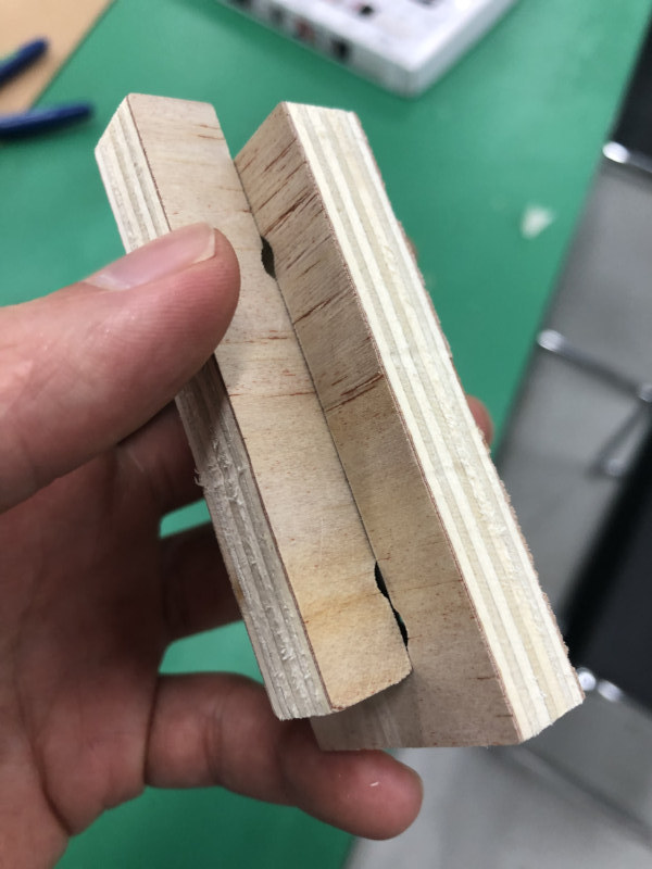
In joint test
Gave a clearance of the hook joint to check if it was fit well. I found that slots related to the thickness of the material needed to be given more clearance at least 1mm.
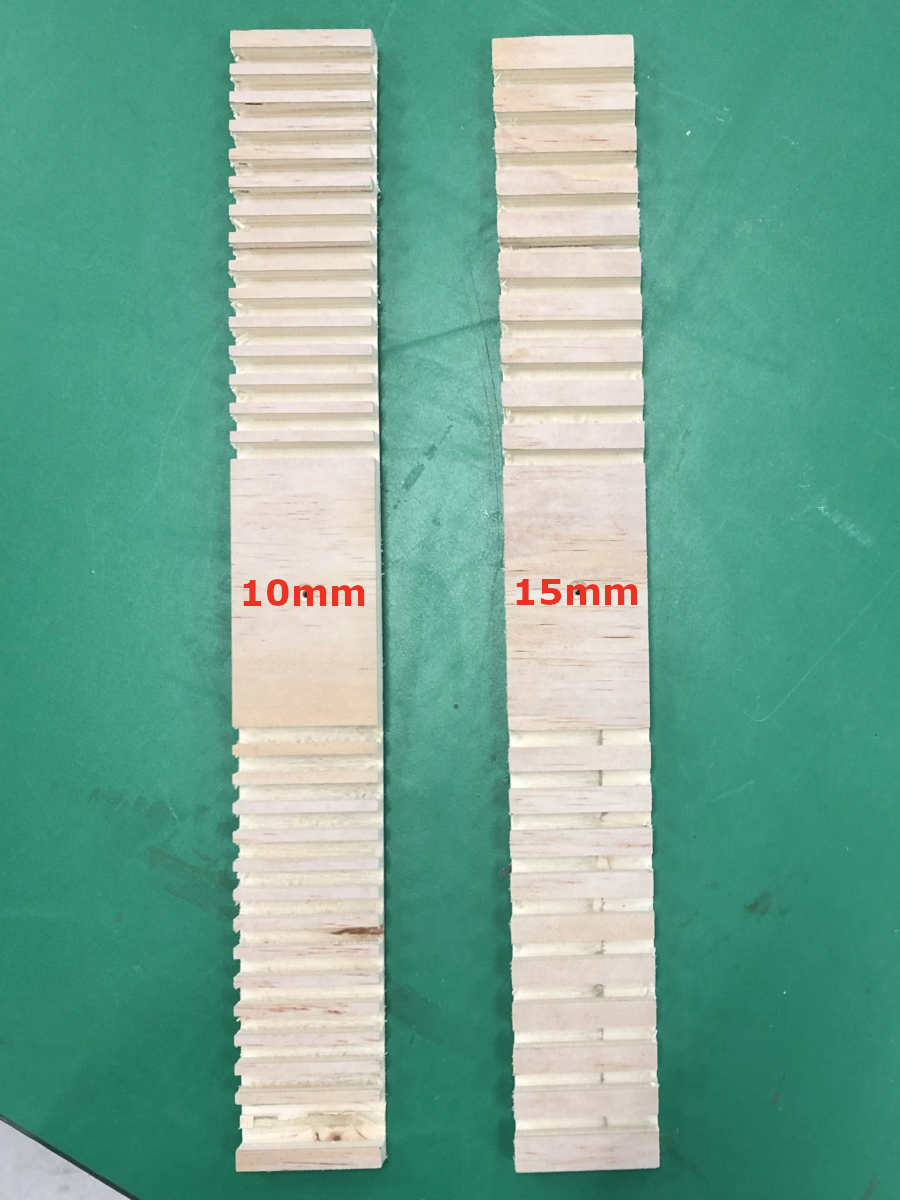
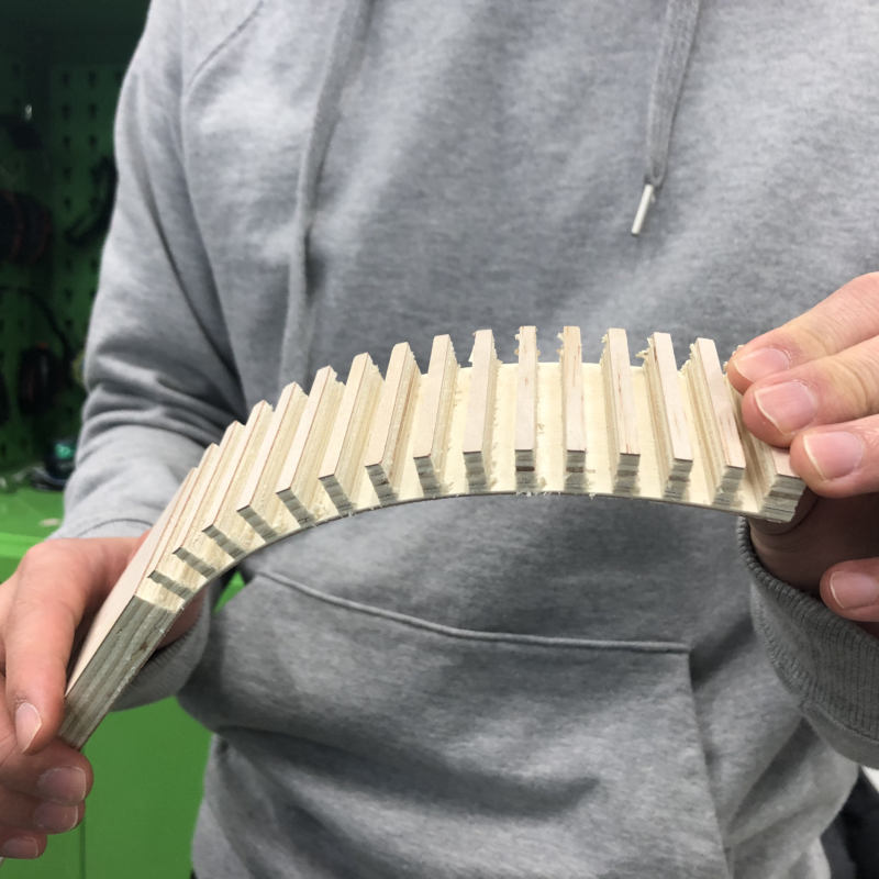
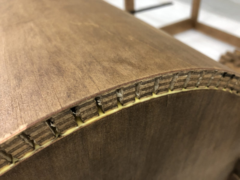
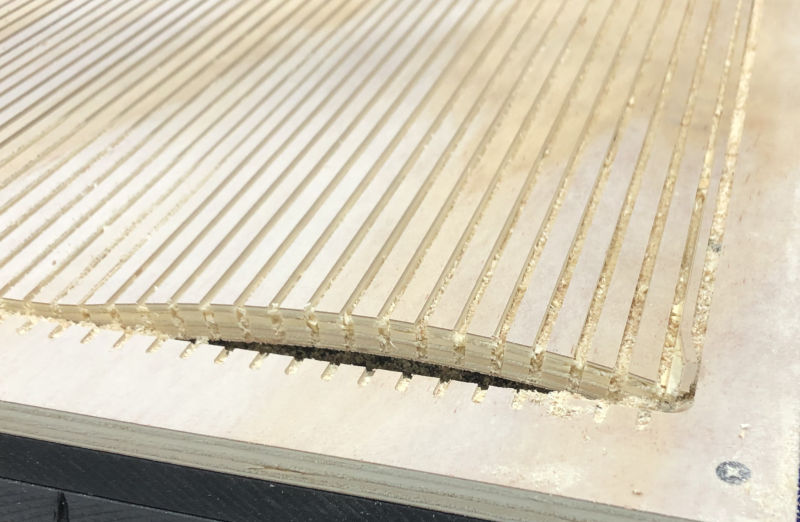
In saw kerfing
Tested how much space should be left to bend, and how much space should be given depending on how much bending is achieved. The re.maining plywood thickness was 2mm and 3mm. Gap between line was 10mm and 15mm. It bended well when the remaining thickness is 2mm, but when it is 3mm, there is almost no curve. And the narrower the interval between, the better the bend.
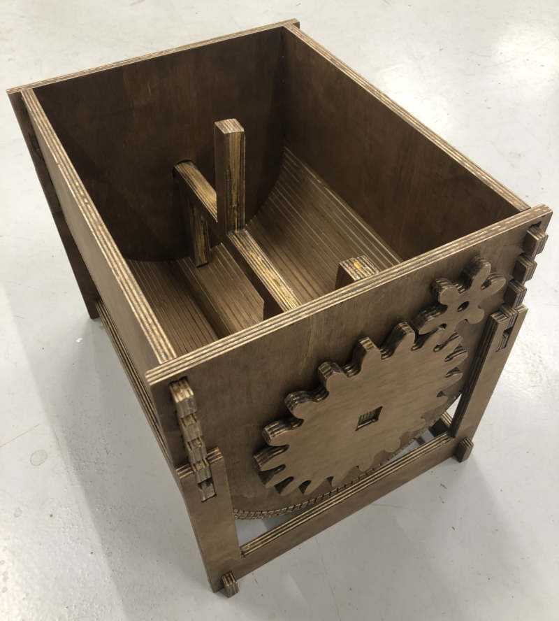
Modify Design
- The parameter values were changed to match the size of CNC.
- The height of the upper part, which is less important than where the pedal is operated, has been reduced.
- Support was made to stand the prototype.
- I tried to put a small gear on the support, but it failed because of a slight difference in position.
- I gave a little more clearance to the connection. 1mm on both sides
V-carve
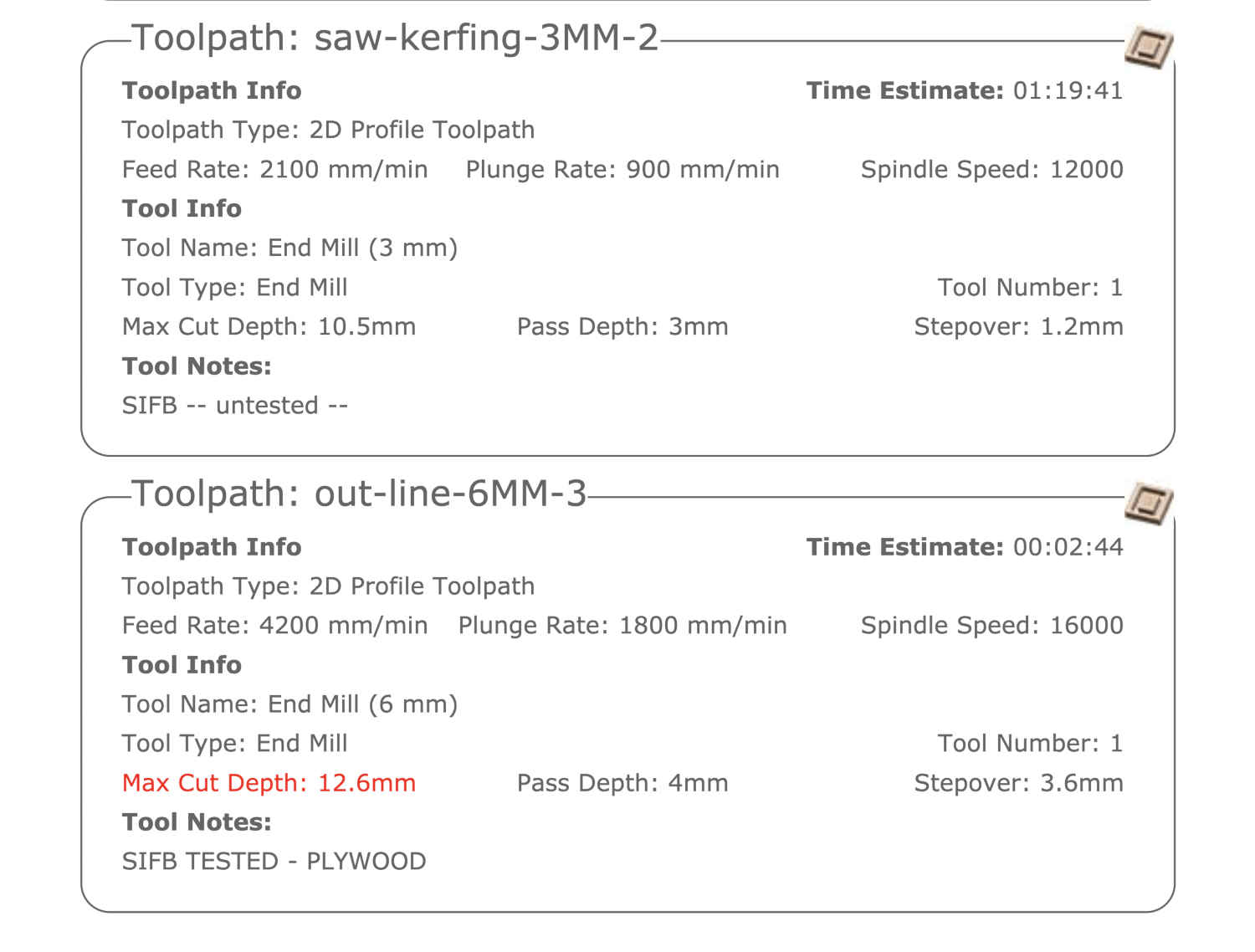
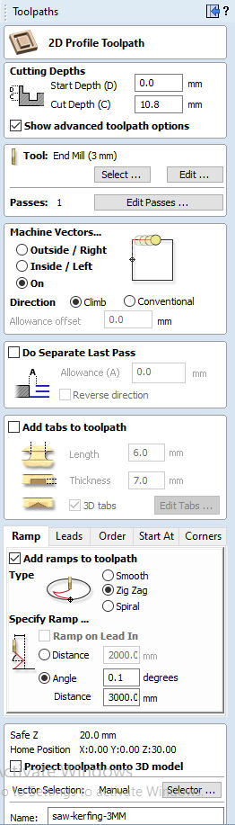
Attach job sheet to refer to feed rate, flange rate, and spindle speed of 3mm and 6mm endmill. (For information on 6mm endmill, refer to the experiment in group assignment.)
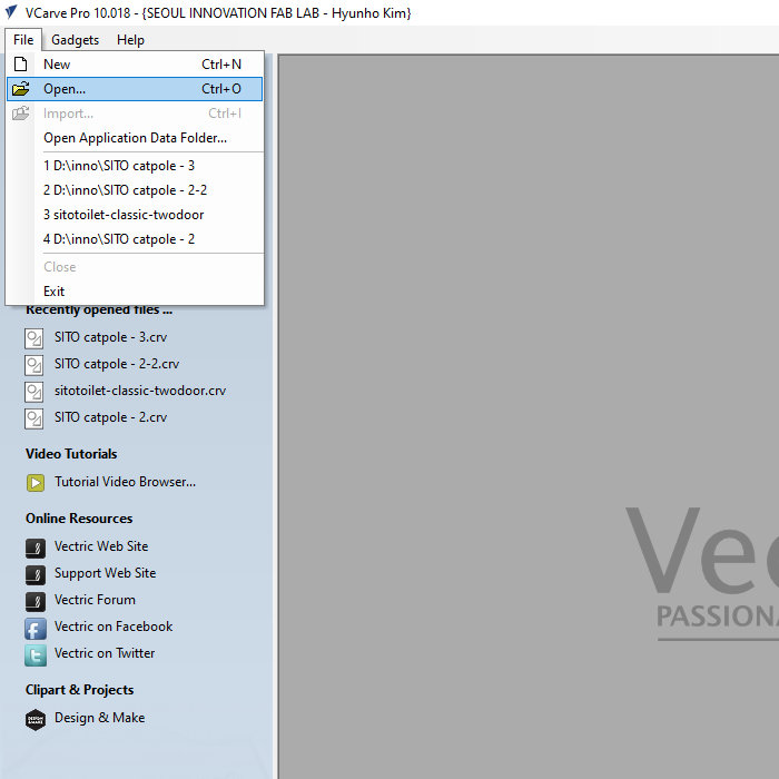
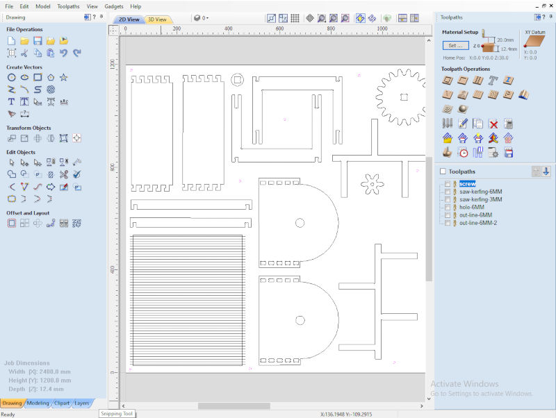
- Opened V-carve.

- Opened the .dxf file. (Click import to attach another design to an existing design file.)
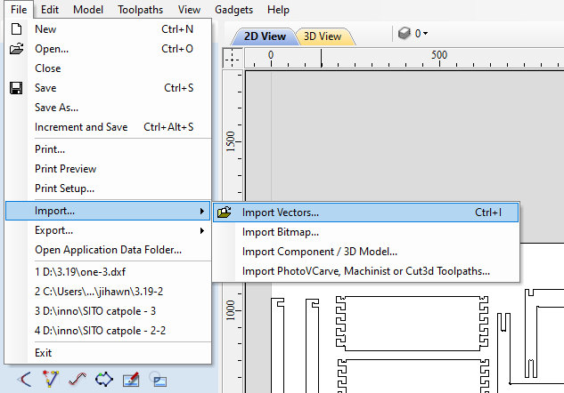
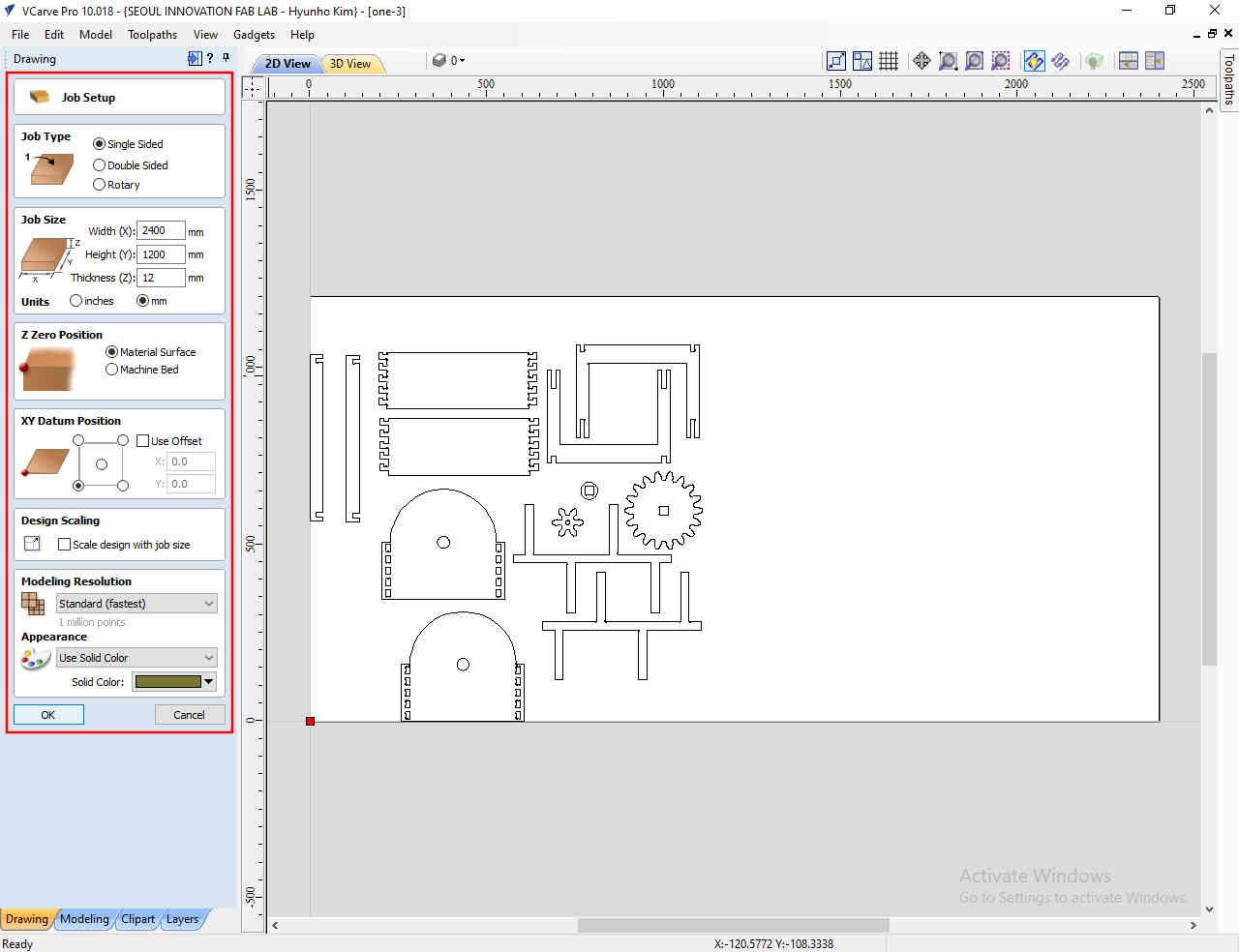
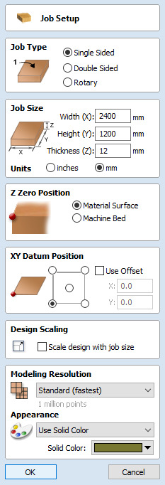
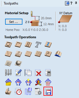
- 'Job Setup' - Clicked OK button
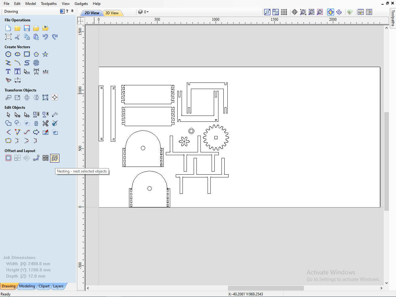
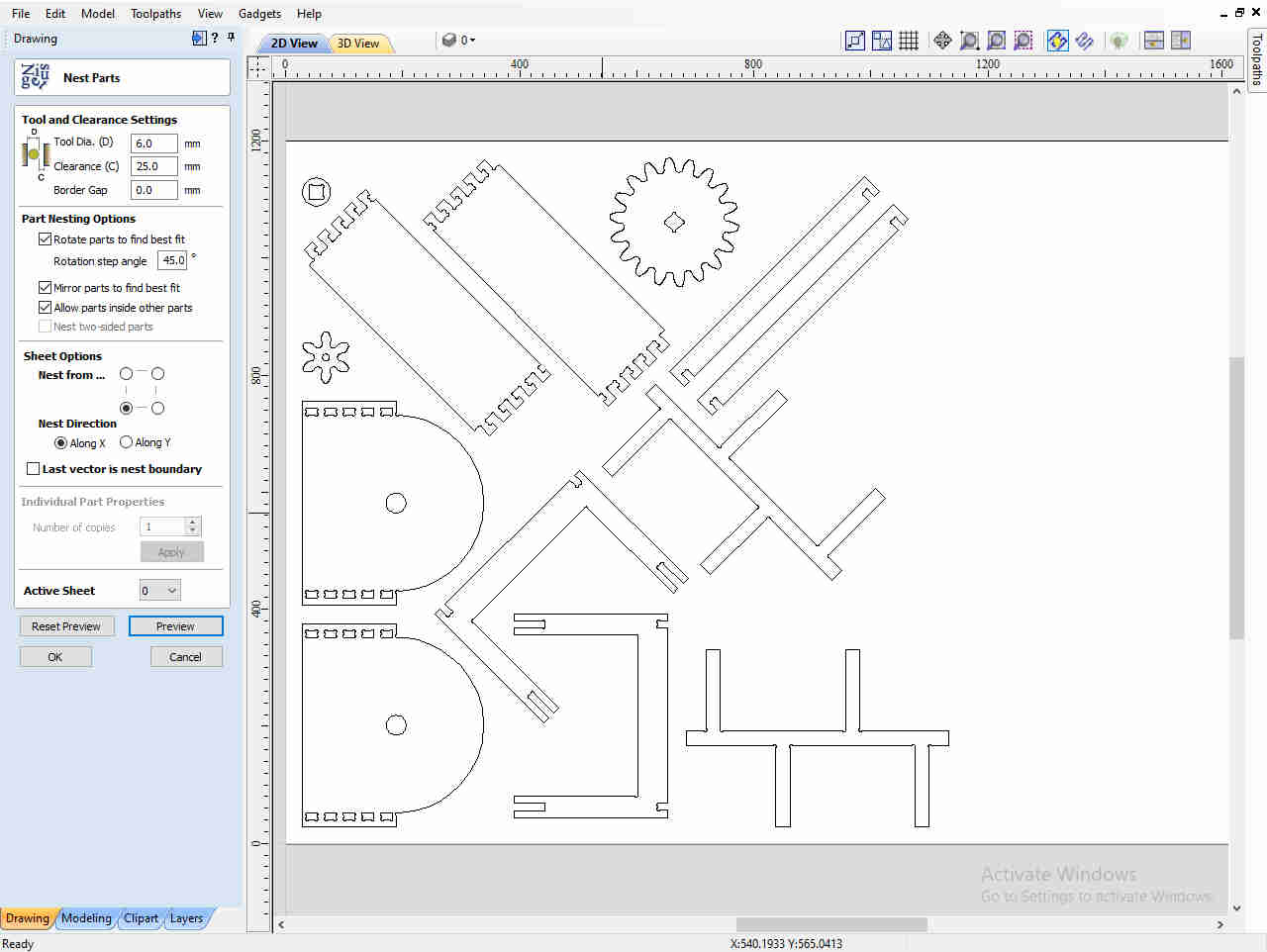
- I used the 'Nesting' function to arrange parts of desing, but there was a phenomenon where several parts I designed overlapped and the outline of the gears was.
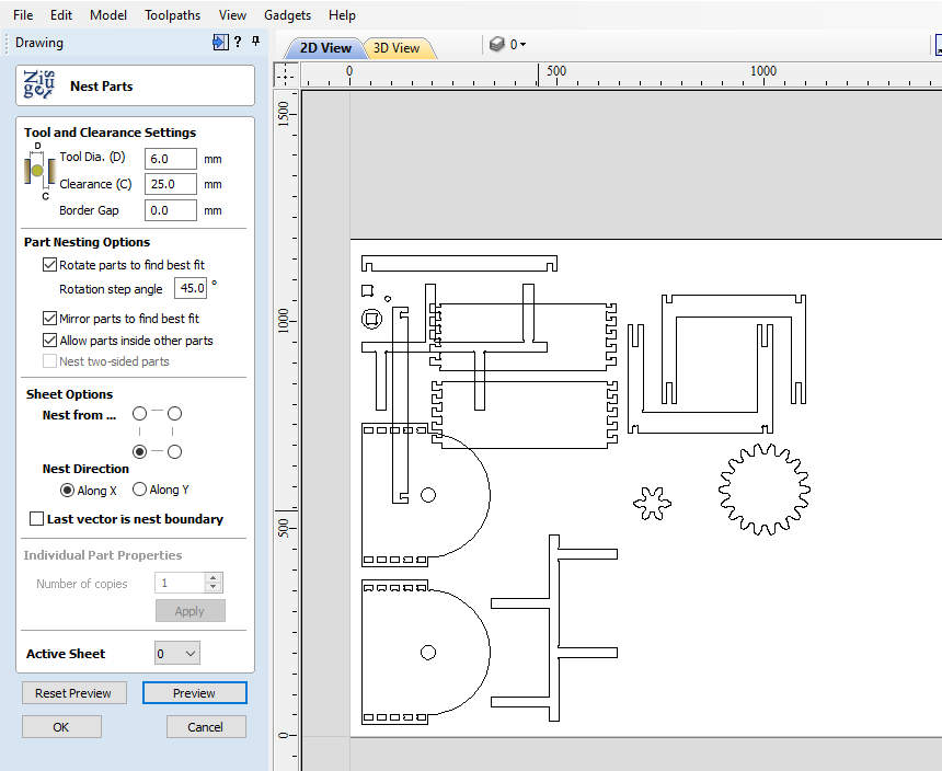
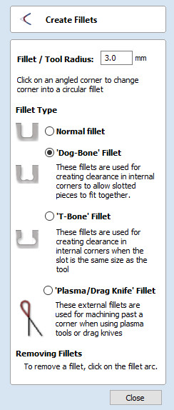
- Can be made a 'Dog-Bone' in the 'Fillet' setting.
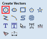
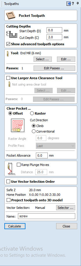
- Pressed 'Draw Circle' to draw counterbore holes. And I selected the 'Profile' to create a task for screwing.
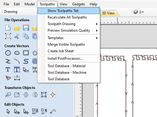
- In the Toolpaths tab, clicked Show Toolpaths Tab.
- Work was divided into Saw kerfing parts, inner holes, and outline by using Profile function.
- Using Profile, Made screw task, engraving task, cutting inside holes task and cutting outline task.
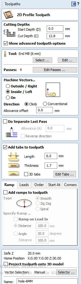
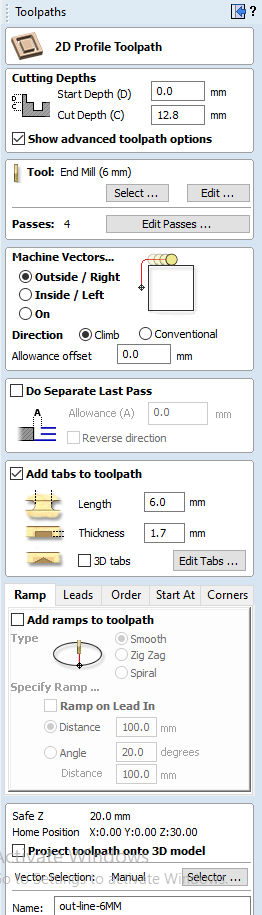
- In cutting outline task, I had to add tabs to fix the parts of the design.
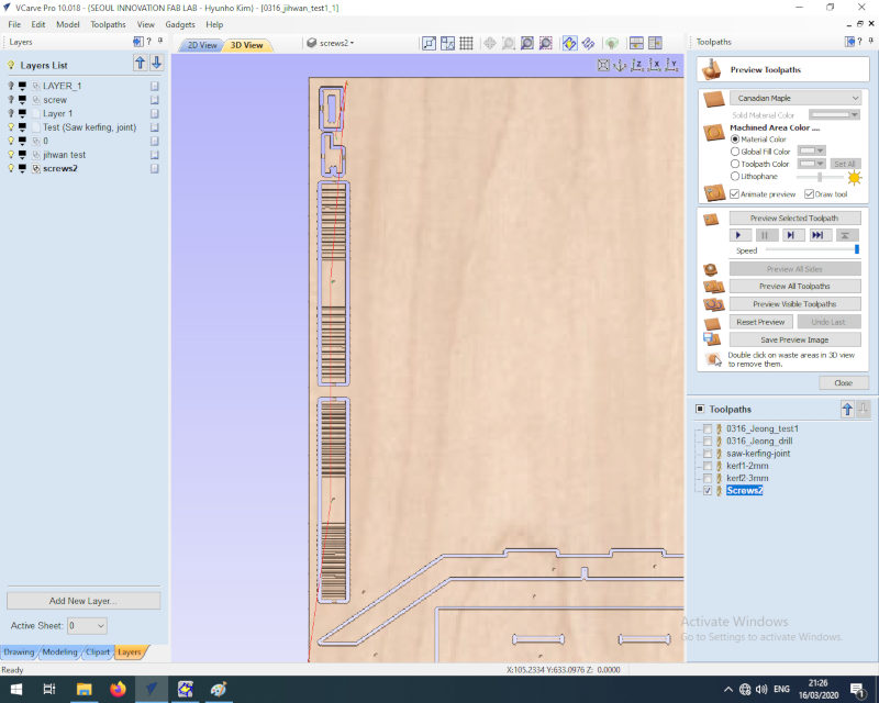
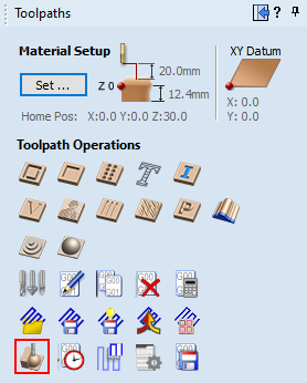
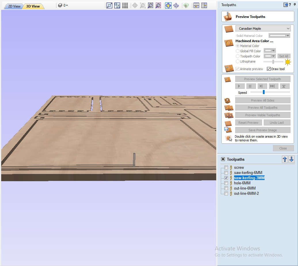
- And I clicked the 'Preview Toolpath' to see exactly what they will produce when cut into the material.
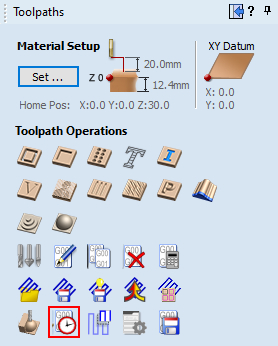
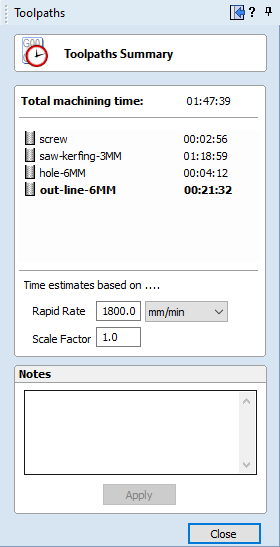
- Clicked the 'Toolpath summary' to confirm the machining time
- Clicked the 'Toolpath summary' again.
- Clicked the 'Preview Toolpath' again.
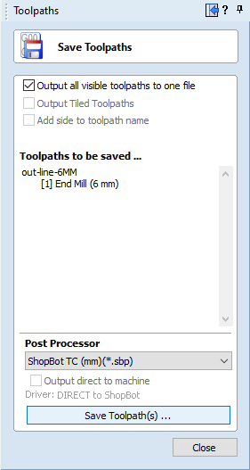
- Clicked Svae Toolpath. Selected Shopbot TC (mm) (*.sbp). And then Clicked 'Save Toolpath(s)...'
An error occurred that was selected but not recognized.
1) I got help from my instructor.
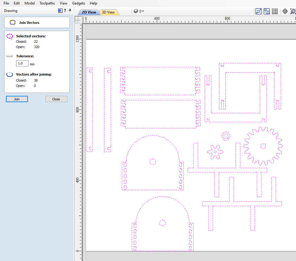
2) I asked my instructor about it and realized that I should connect the parts that look like one but are not connected, and I could do it using the 'Joining and Closing Tool' function.
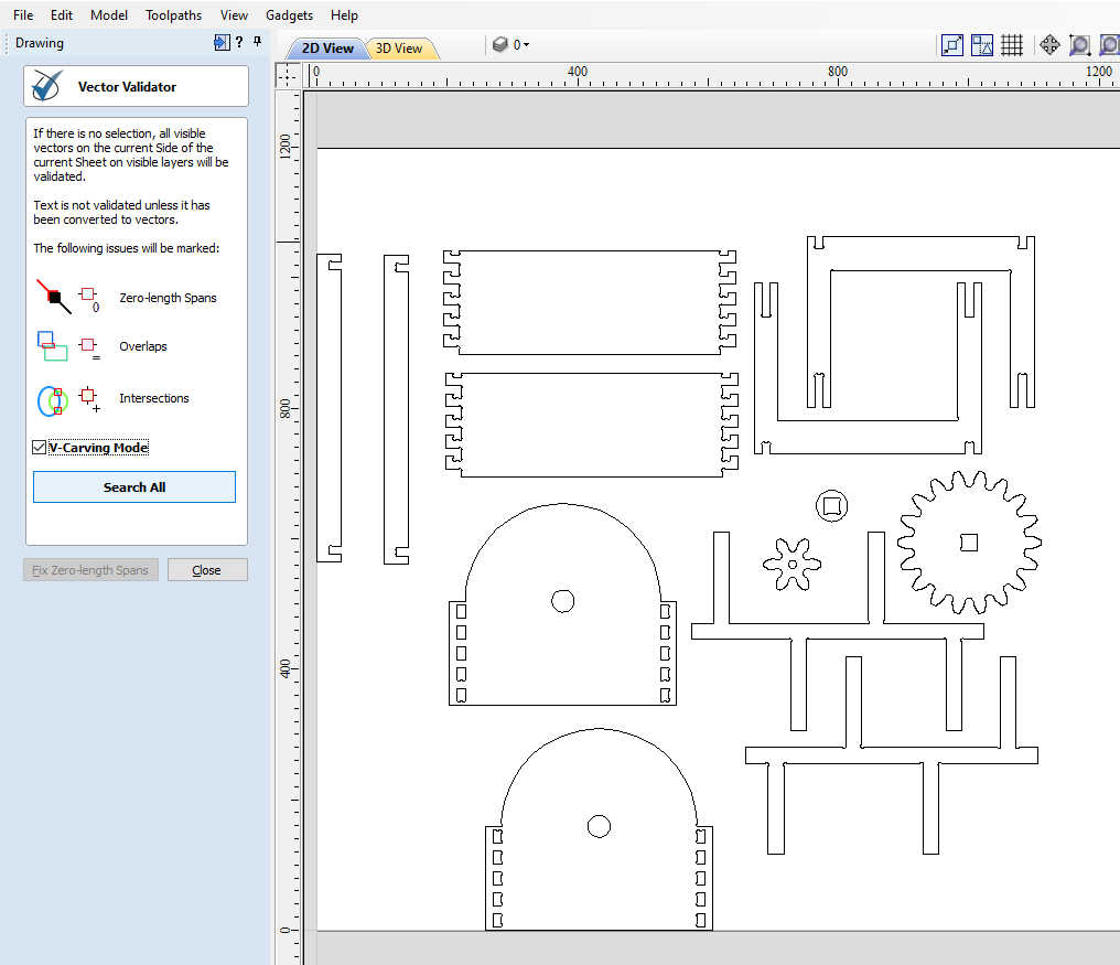
And I found one more error: finding overlapping lines. I could find it by using 'Vector Vaildator' function.
1) When using the function, initially use the 'Joining and Closing Tool' to connect parts that are not connected.
2) Use the 'Vector Vendor' to solve design issues.
3) Use fillet to add the dogbones.
4) Then I could use the 'Nesting' function without error.
1) In engraving task for saw kerfing, Confirmed that it takes too much machining time.
2) In 'Preview Toolpath' of engraving task, It repeated, cutting once, returning to the position where it started cutting until the set depth was completely cut.
In Profile Toolpath, Selected 'Ramp' of 'Profiling Options' for changing spindle movement and chose the Zigzag option. (It was possible to reduce the working time by 2 hours from 3 hours 30 minutes to 1 hour 20 minutes.)
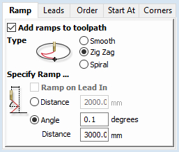
1) When machining time takes too long.
2) First, check the preview to check the spindle's movement.
3) And then, By changing the spindle's movement, the working speed can be reduced.
Shopbot
- Wore Eye and ear protection.
- To immediately stop the spindle/router and all motors, use the red emergency stop button or switch, which will cut off power to all systems. And then, To start working again, you will need to re-zero all axes because the locations will no longer be accurate.
- Turned on Shopbot by turning power switch to the right in control box.
- Pressed the "Reset" button on the three button pendant.
- Open 'shopbot 3' program.

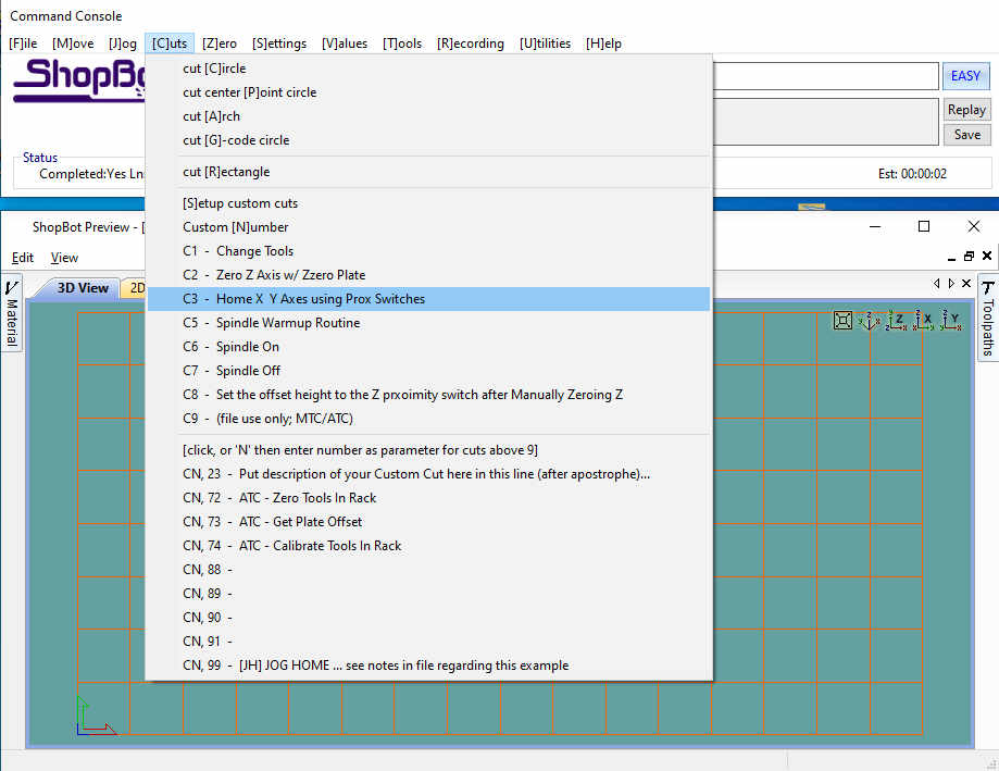
- Cut - 'C3 - Home X Y Axes using Prox Switches'
- replaced endmill using wrench attached in control box.
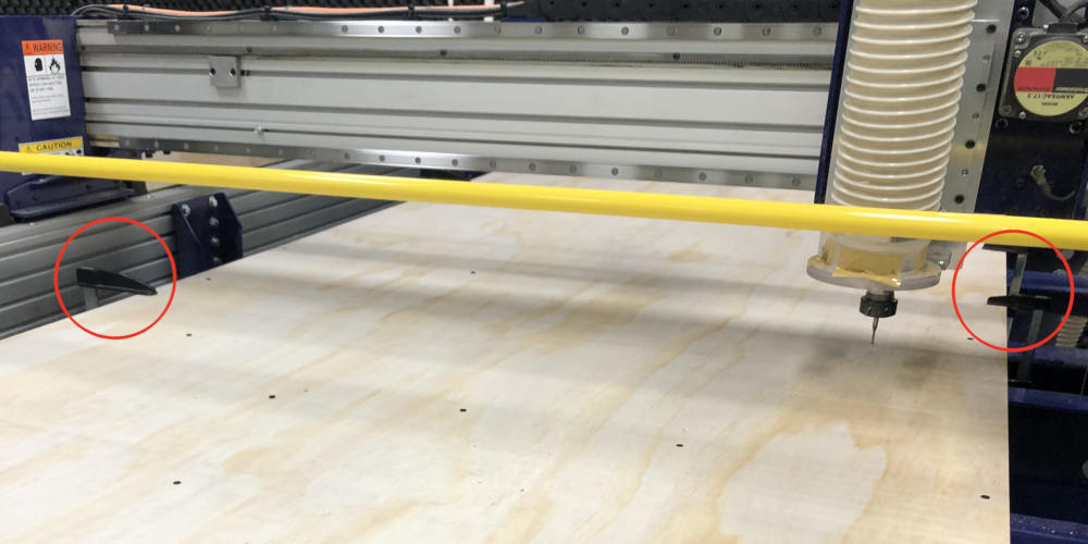
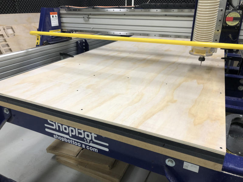
- Set up material(plywood). Then secure the material with a wood clamp before screwing. (There was no photo, so I used a picture taken after running the screw path.)
- Cut - 'C2 - Zero Z Axis w/ Zzero Plate', Place the grounding clip on the endmill, if possible. Otherwise, place it on the collet nut or shaft of the spindle. Set the plate down directly beneath the endmill.

- Set origin
- Inserted this key into the safety lockout next to the power switch and turn the key to “ENGAGED”.
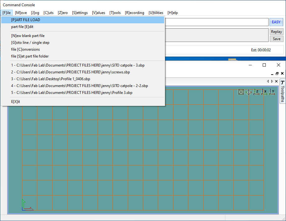
- Opened .sbp file.
- Turned on the vaccum machine.
- Clicked Start button. In "NOW STARTING ROTER/SPINDLE" window, before clicking OK, Pressed the “Start” button on the three button pendant.
- First, ran the screw profile to make counterbore holes.
- Then, used an electric drill to drive in the screws.
- The middle part of the plywood was so bent that we had to screw in three times.
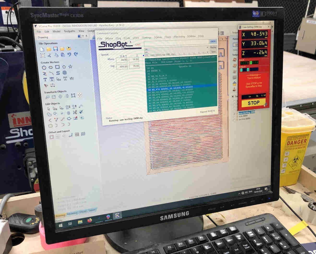
- And ran engraving profile.
- After end of engraving profile, replaced 3mm endmill to 6mm.
Andmill Replacement Processes in the middle of Work
1) C3
2) Replaced 3mm endmill to 6mm.
3) After the replacement of the endmill, I retook the z axiz Using Zero Axiz.
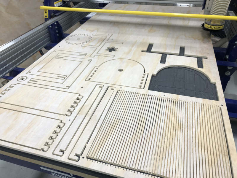
- The inside holes profile and the outline cutting profile were proceeded one by one.
- Done
- Removed the taps, screws.
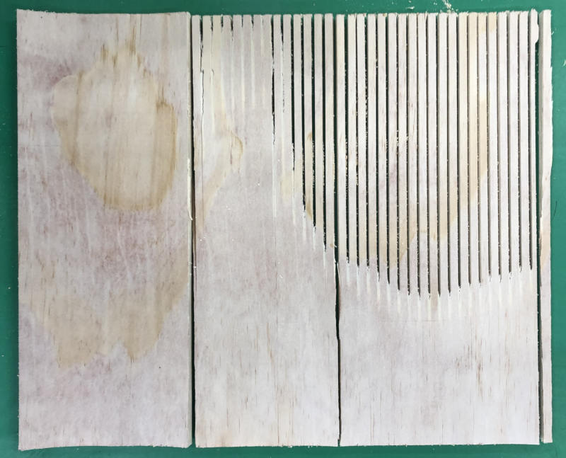
Problem 1
1) The tabs on the badly bend parts of the plywood were all cut off. Because thhe plywood was so floating that the thickness and width of the tab were not enough.
2) Saw kerfing part ragged. The reason was that the plywood was too bent and I should have put in more screws.
 Solution
I came to Fablab early the next morning.
Put more screws around the cut.
Modify tab width and thickness to 6mm, 1.7mm
Then Cut it again and successfully cut it.
LearningThere are more things to consider when plywood is in bad condition.
Screws should be sufficiently inserted to prevent plywood from floating.
The best thing is to choose a flat plywood that is not floating.
It is recommended that the thickness of the remaining parts be 1.2 to 1.5mm, rather than 1.0mm.
- Finally, Included my .html job sheet from V-carve.
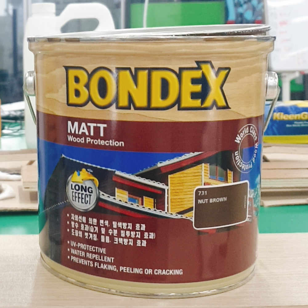
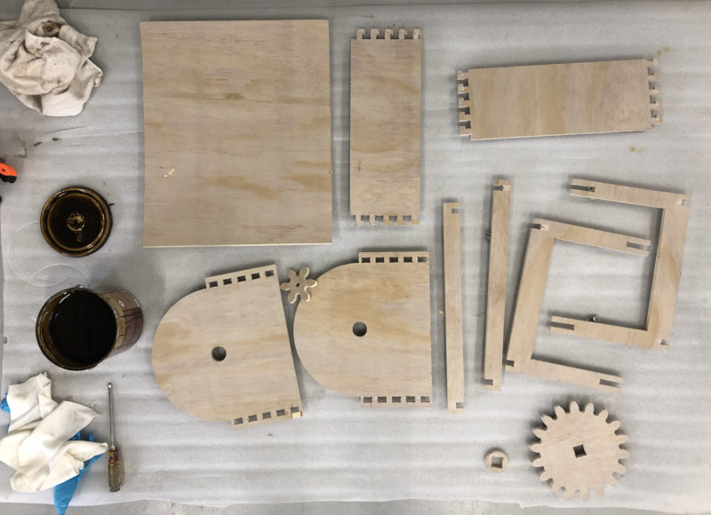
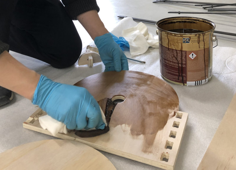
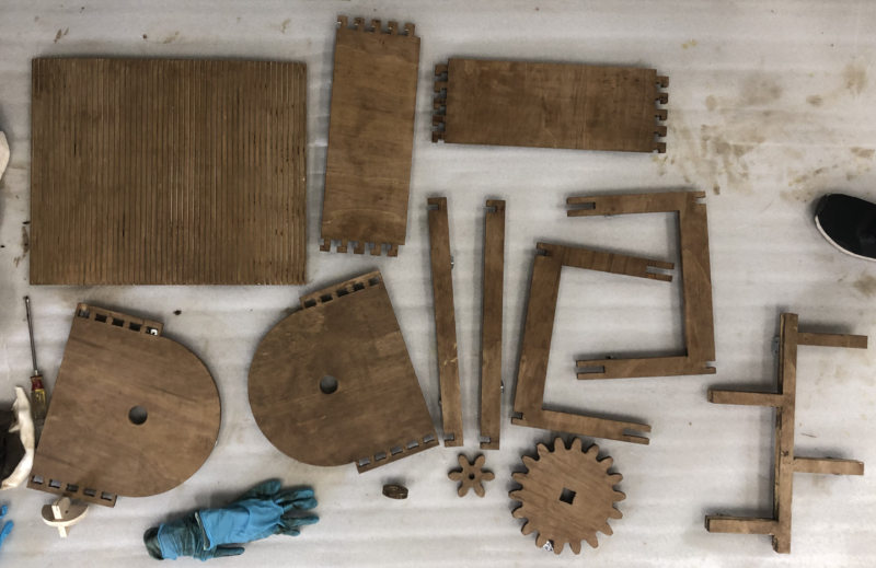
Etc
I applied this finishing material to my work.(The picture was sent by Jeonghwan.)