3D Scanning
Capture Scanner (3D System)
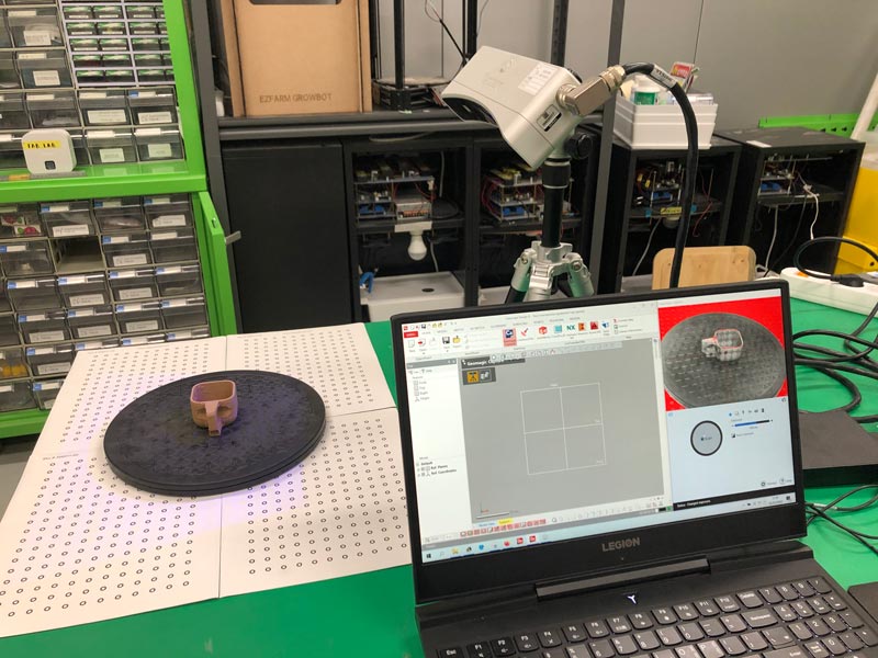
The Geomagic Capture 3D scanner is a structured-light scanning system that uses a blue LED light system.
- Connected all cordsets to the Geomagic Capture scanner.

- Connected the Geomagic Capture 3D scanner to the PC using a CAT5e Ethernet cable.
- Placed the cup on the stable plate.
Geomagic Design X
Comprehensive reverse engineering software, combines history-based CAD with 3D scan data processing.
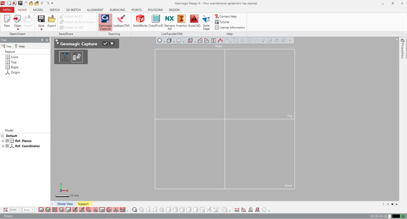
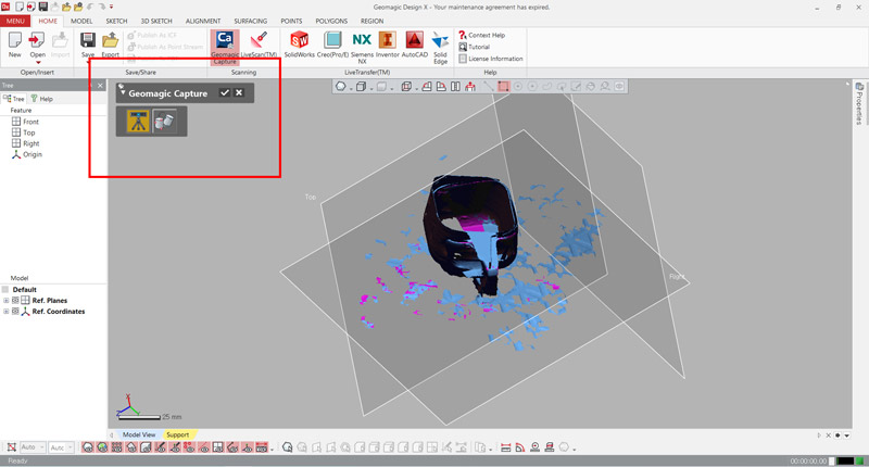
- Opened Geomagic Design X.
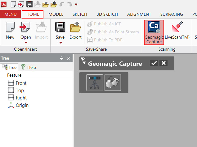
- In the HOME tab, in the Scanning group, clicked Geomagic Capture.
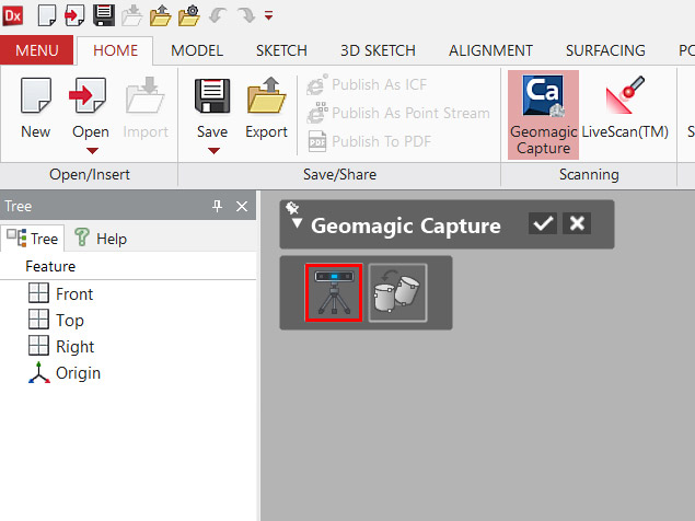
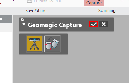
- Clicked scanner icon button to connect to the Geomagic Capture 3D scanner and start scanning the part.
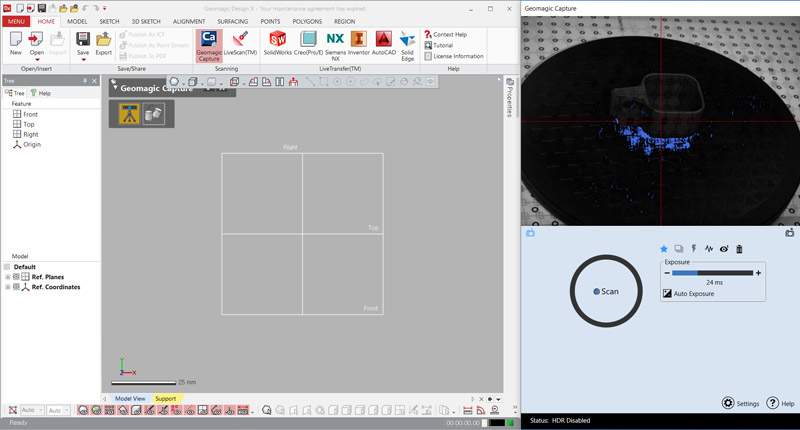
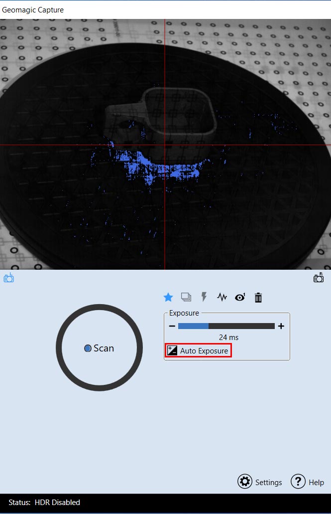
- Adjusted the Exposure setting to click Auto Exposure.
- Then clicked Scan. A scan was taken and imported in the application.
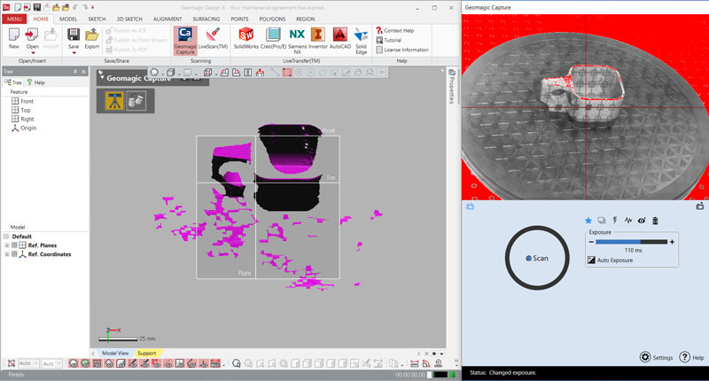
- Continued scanning until the project was completed and clicked Accept
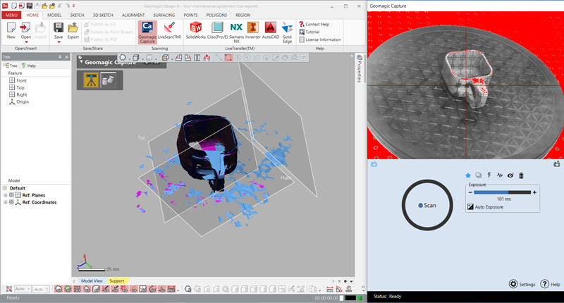
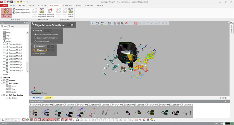
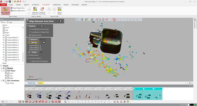
- To make each scan more accurate, In the ALIGNMENT tab, in the Scan to Scan group, clicked Align Between Scan Data.
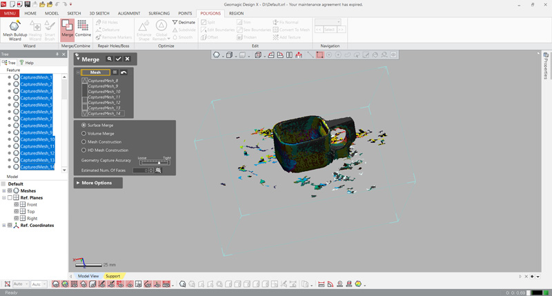
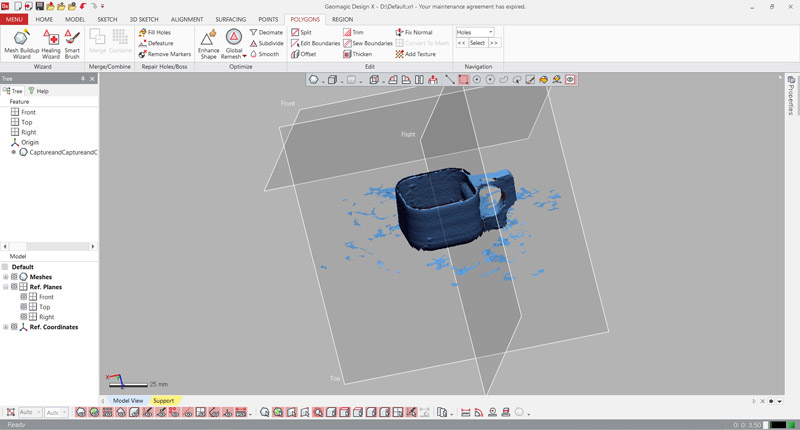
- To unite into one, In the POLYGONS tab, in the Marge/Combine group, clicked Marge.
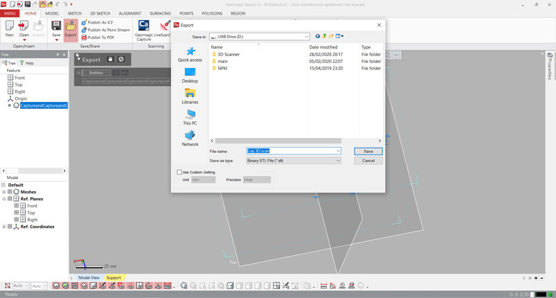
- Then clicked Export in the HOME tab, in the Save/Share group. And saved file as stl.
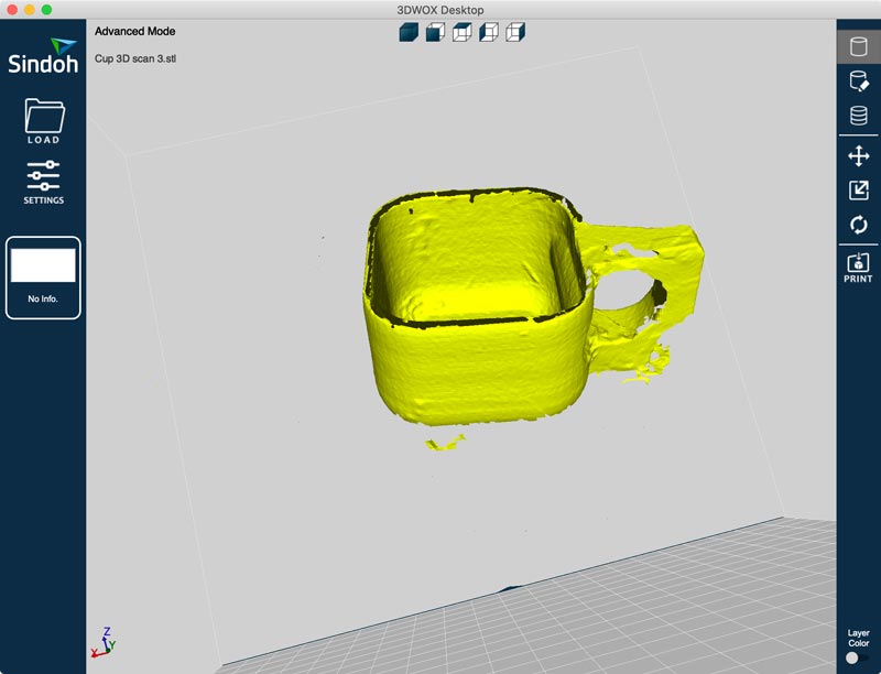
- I opened file in 3DWOX Desktop. But I didn't print the file.
There was a problem where the images did not combine if the angles were turned a lot in the scanning section. And many attempts have been made to find a well-coordinated angle.
I attached a video link for user of Design X with geomagic capture.
Meshroom
Free, open-source 3D Reconstruction Software based on the AliceVision Photogrammetric Computer Vision framework.
- First, my partner (Yunje) took several pictures of me from various angles.
- Transferred the pictures of the camera to the computer.
- Imported images into this project by simply dropping them in the “Images” area.
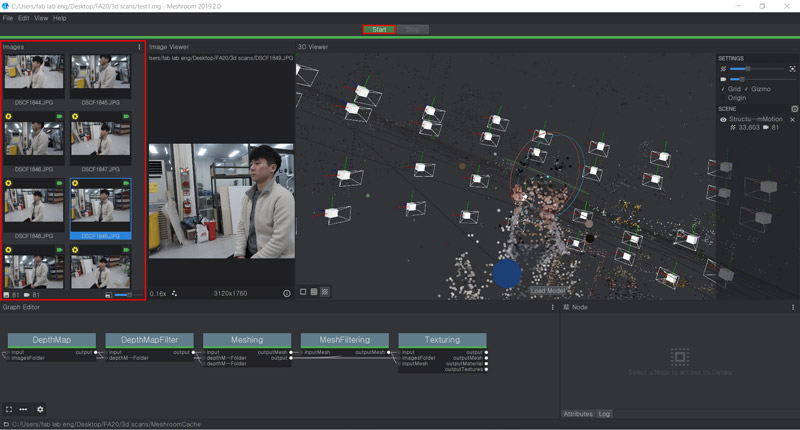
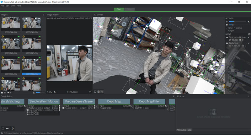
- Pressed the “Start” button and waited for the computation to finish.
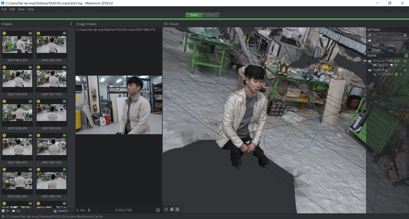
- Result (I uploaded the .obj file using the Sketchfab site.)
1) Open the .obj file in meshlab.
2) Remove unnecessary parts of the scan file.
3) Export the organized file.
4) Enter the Sketchfab site and press the upload button.
5) After uploading, press the save button and publish button.
6) Go to My Profile and click on models.
7) Press the embedd button and copy and paste the code.
It was a program that could be used very simply as a drag-and-drop system. It was my favorite part. However, There was some time and computer fever in the computation of the pictures.
I attached Meshroom tutorial.
3D Printing
Workflow
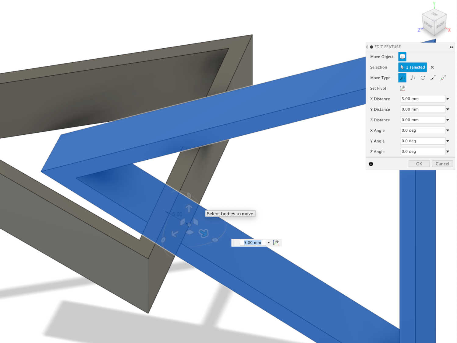
- Designed structure with Fusion360.
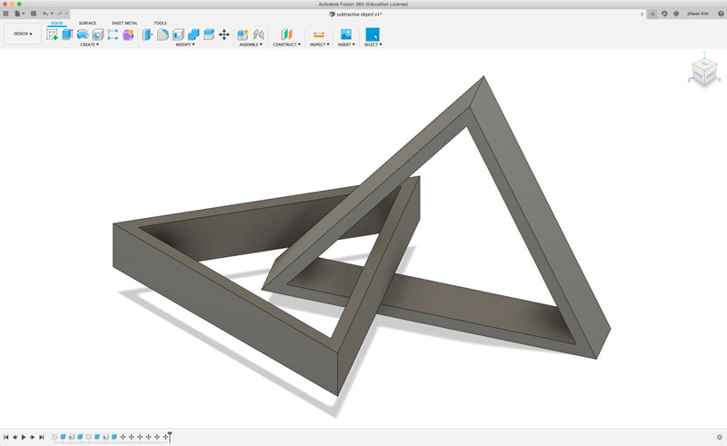
In fusion360, two structures were combined using the move/copy function.
- Saved file to cloud.
- Exported file as stl.
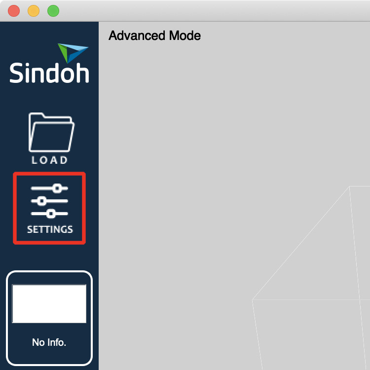
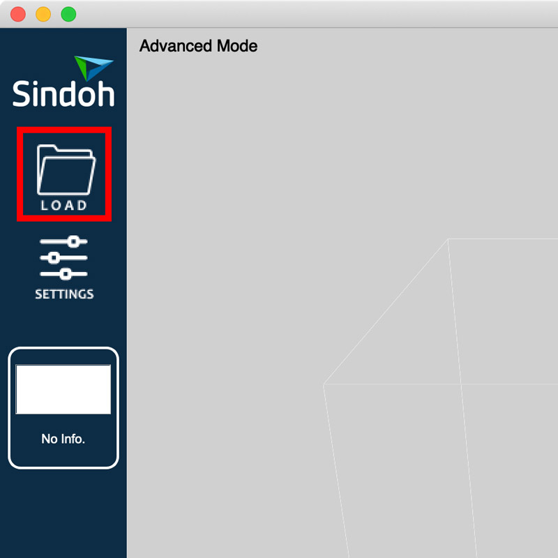
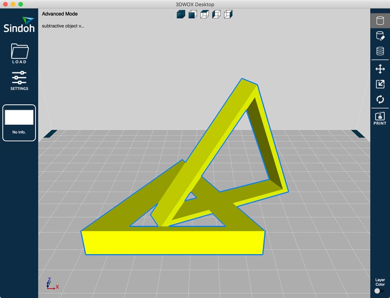
- Opened '3DWOX Desktop'.
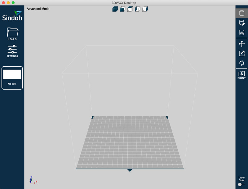
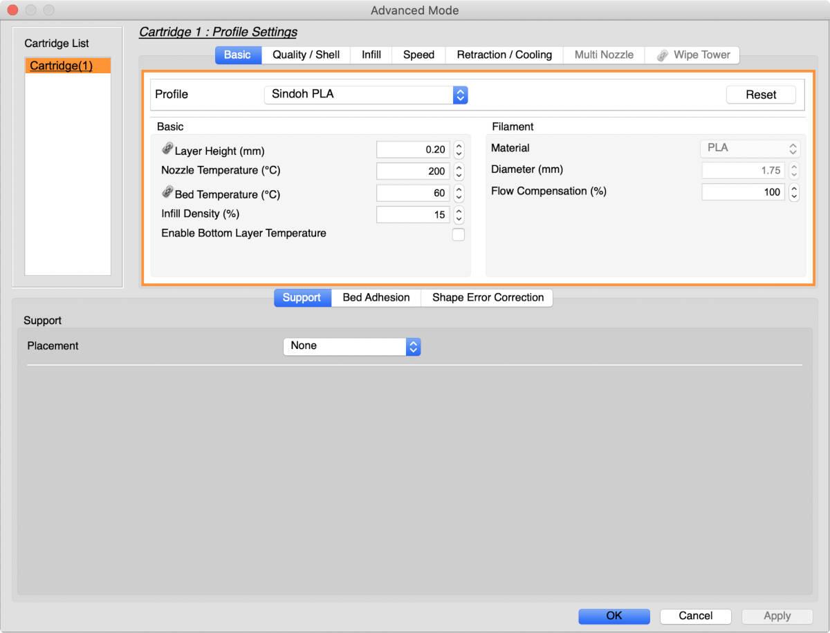
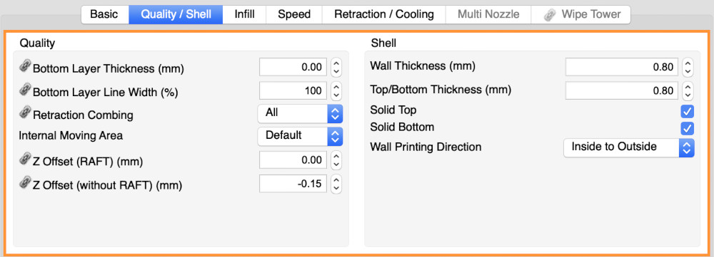
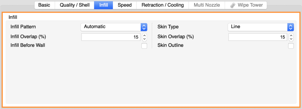
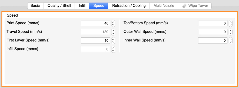
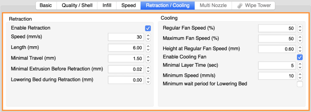
- I went into the setting and checked.
- Loaded stl file.
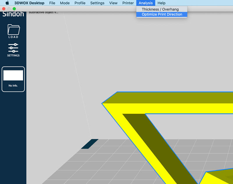
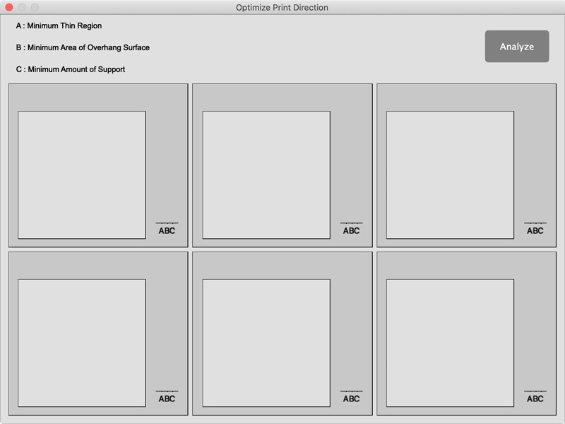
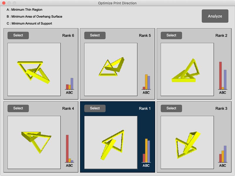
- Click Analysis in top bar - Optimise Print Direction - Analize - choice one you wnat to print - click Select button.
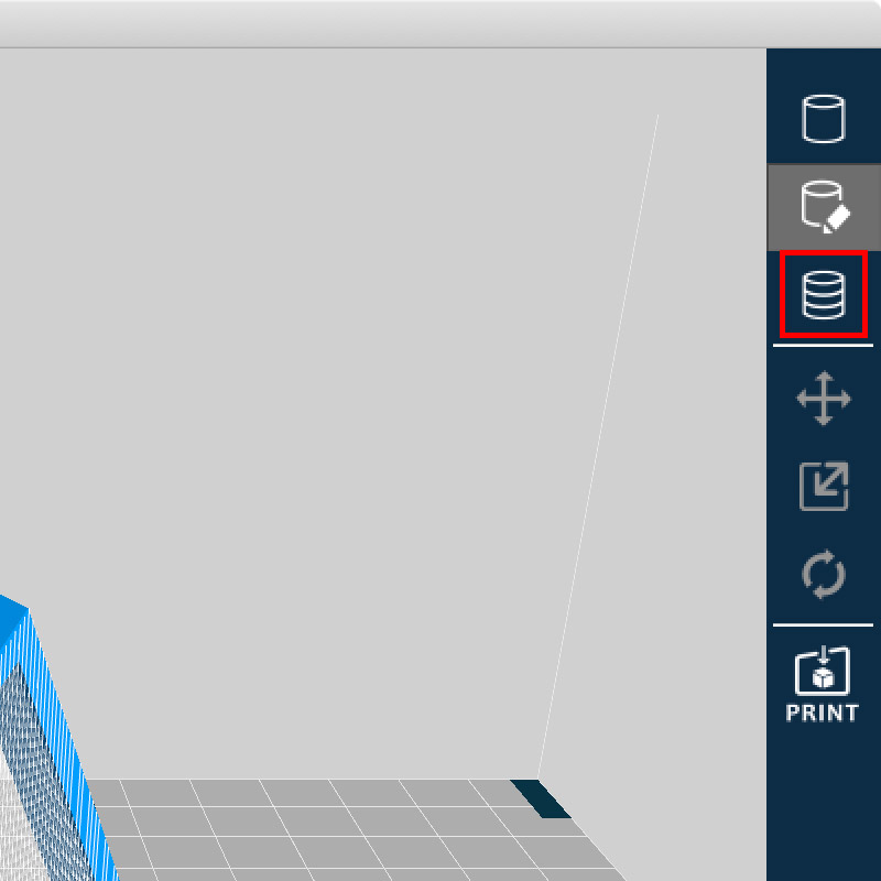
- Click Support Edit Viewer mode button located on right side of screen.
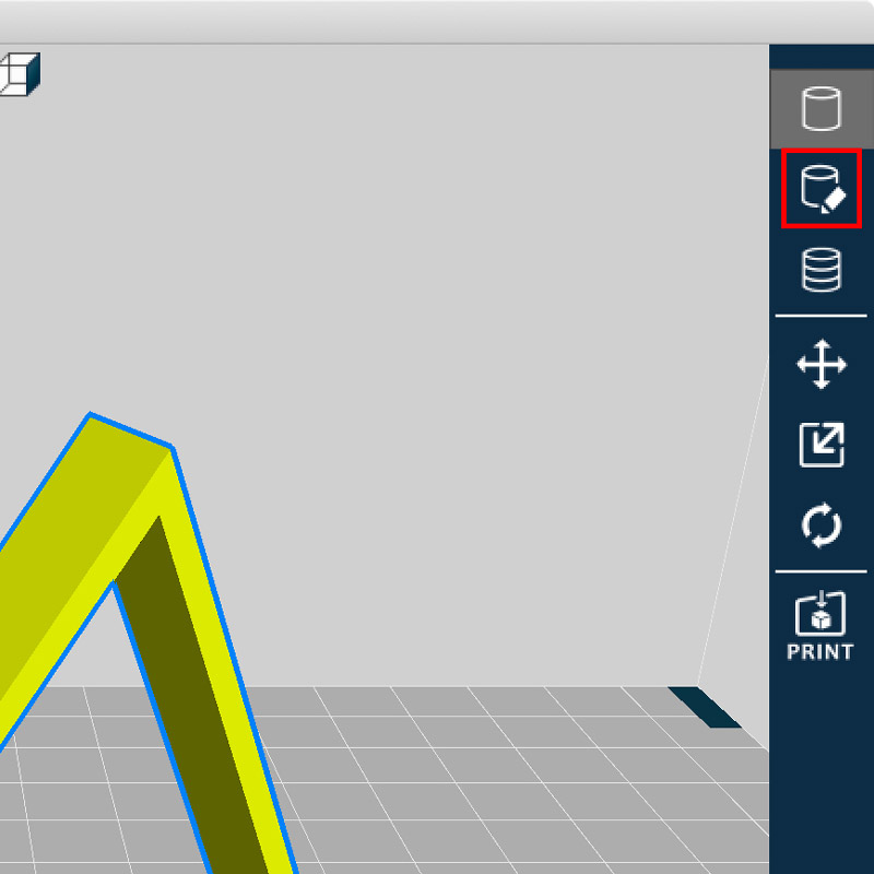
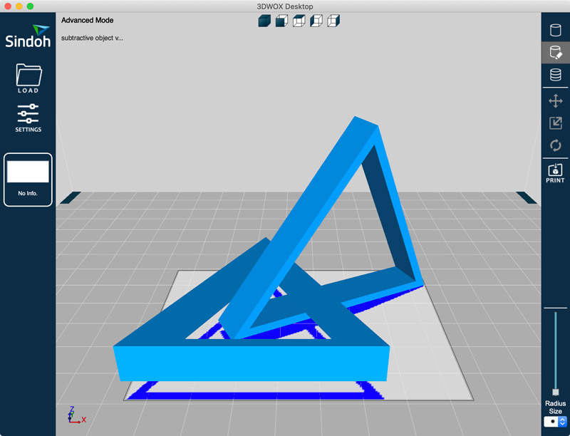
- To create a support, clicked on the inactive area (blue) in the edit region.
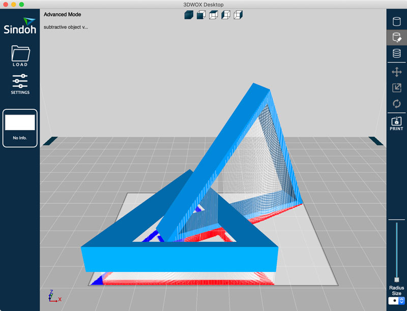
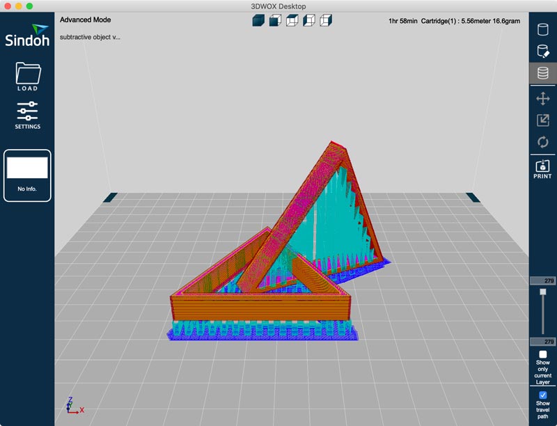
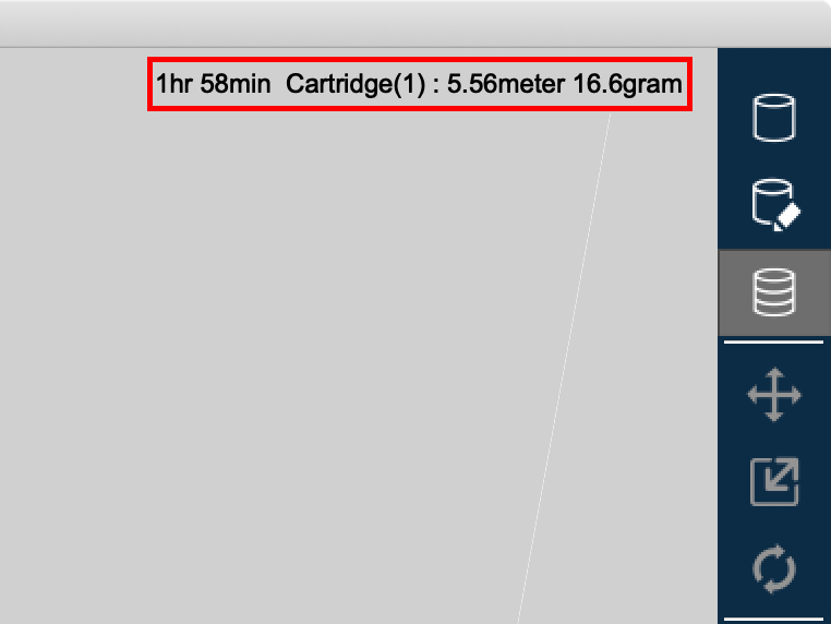
- To check the time it takes, clicked Layer Viewer mode button located on right side of screen.
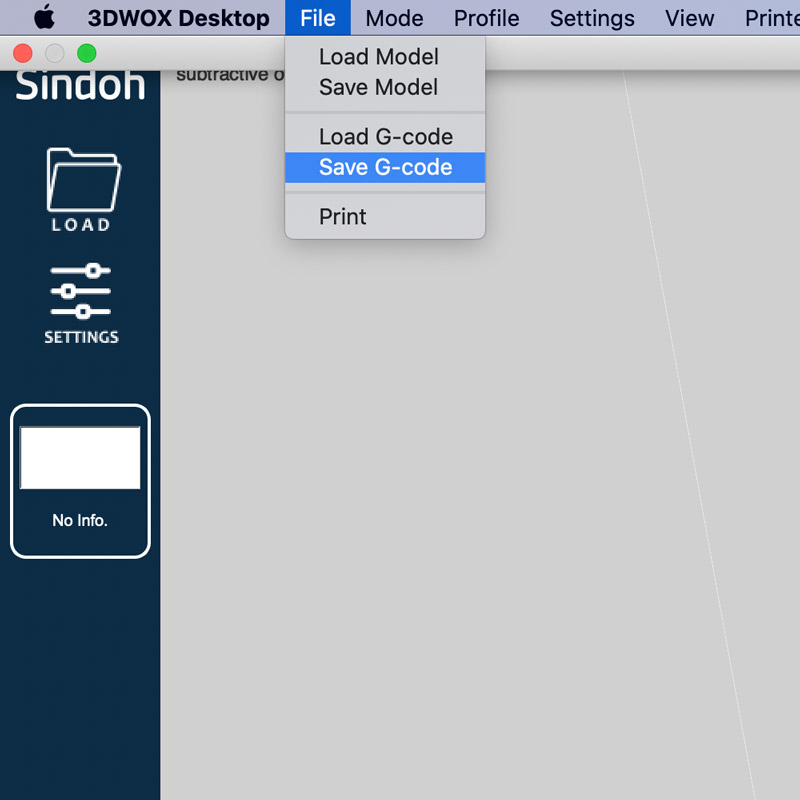
- And then clicked File button located on top bar - Save G-code
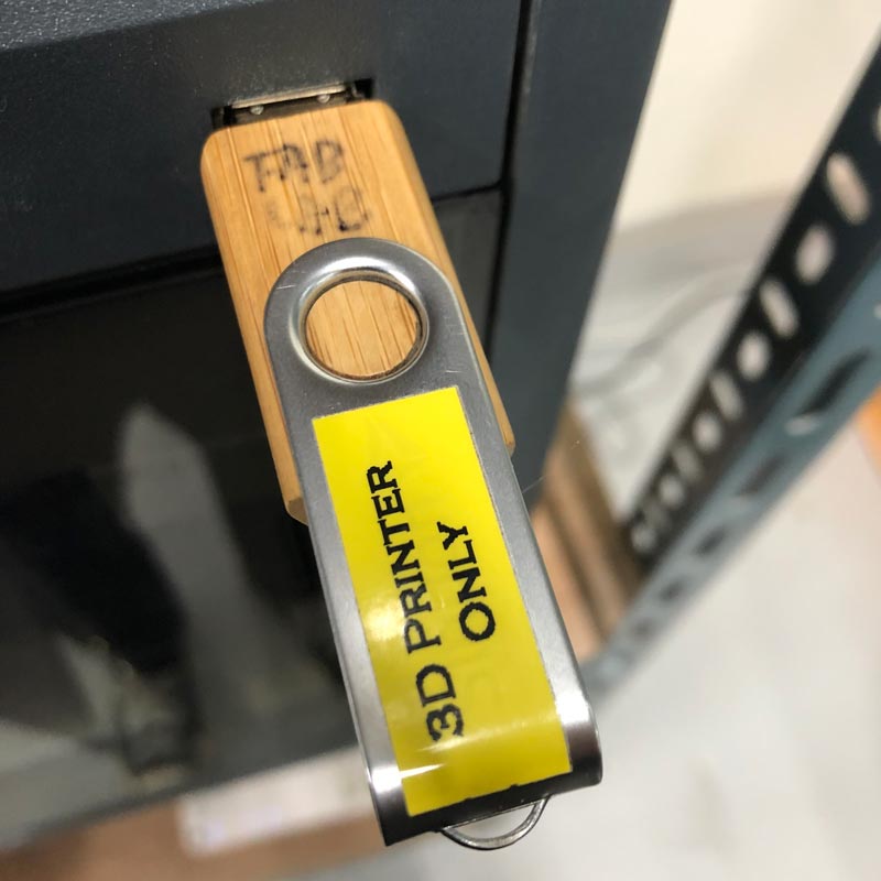
- Moved file to USB. and connected USB to 3D printer.
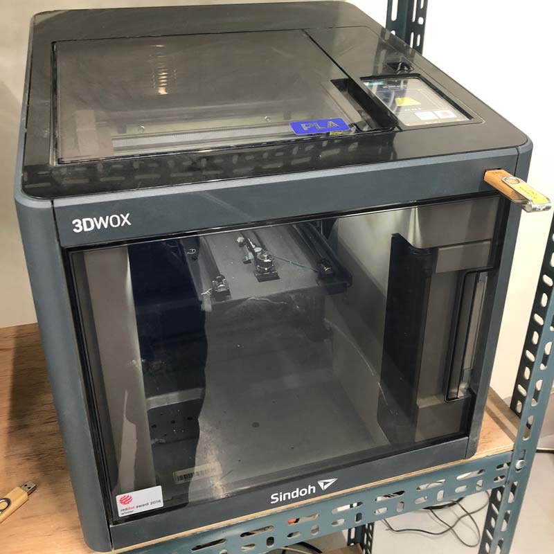
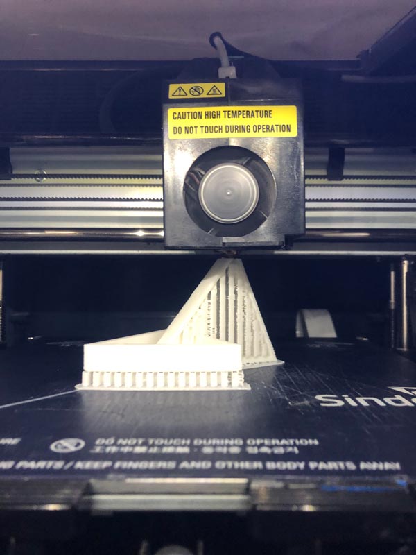
- Output - choice file - play
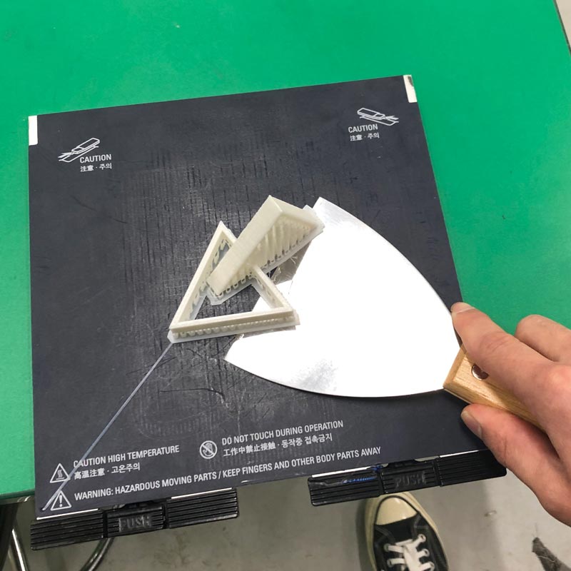
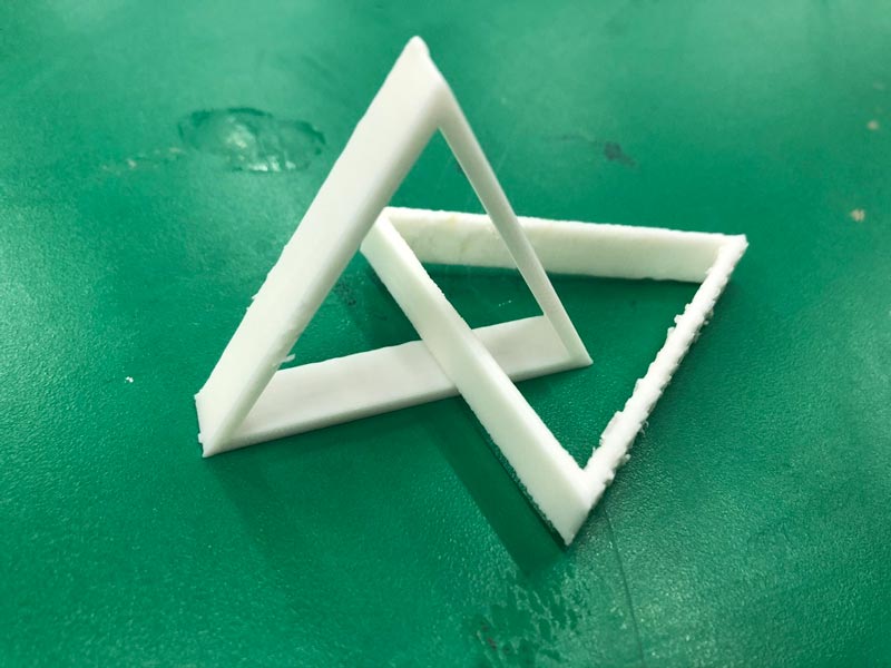
- Result
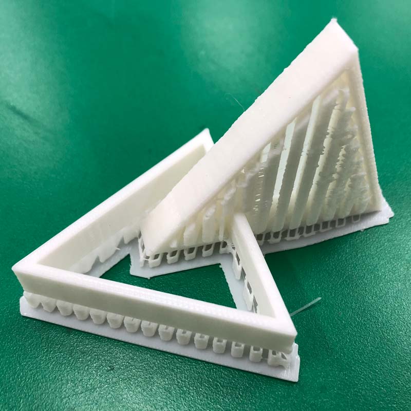
- Etc
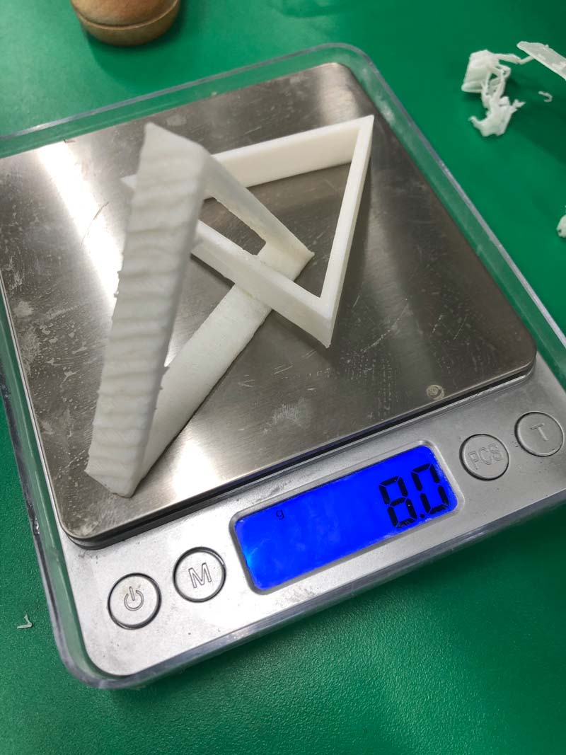
I used many supports. So I measured the weight by dividing it into objects and supports.
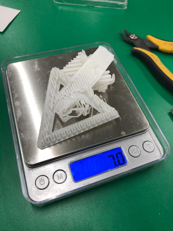
I filled the support with empty spaces in the structure I made, which was useless.
I have already confirmed it with the Overhang distance test in group assignment, and I only had to fill the support in the space between the structure and the floor and between the structure and the structure.
Advantages and Limitations of 3D printing
OVERHANG : Overhang almost needs supporters.
ANGLE : The object's angle is output smoothly from 30 degrees or higher.
BRIGING : Bridging starts to lose more than 0.4mm between them.
DIMENTION : The error of Dimensions is about 0.1 (nearly none).
GAP :The gap between objects does not stick to each other from 0.5mm.
ANISOTROPY : Anisotropy is more horizontal and detailed than vertical.
SURFACE FINISH : The surface finish is sufficiently curved. Not as much as a design program.
INFILL : The infill takes a long time and is too much from more than 15%.(15% or less is adequate)
Each triangle ring is unbroken object. So this 3D object with two rings connected could not be made subtractively.