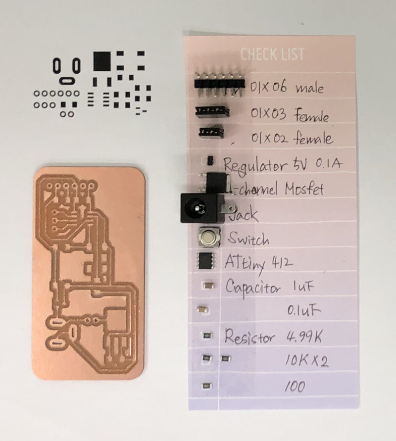
Output Devices
Choose a Output Device
In our fablab, there were 3 kind of heat output device. Among them, I chose the peltier module as the output device this week.
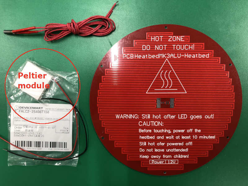
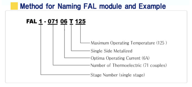
FALC2-25406T150(TEC2-25406T150)
Waht is the peltier module?
The device has two sides, and when a DC electric current flows through the device, it brings heat from one side to the other, so that one side gets cooler while the other gets hotter. The "hot" side is attached to a heat sink so that it remains at ambient temperature, while the cool side goes below room temperature. (Wikipedia)
Read Datasheet
I tried to find a data sheet for this device, but I couldn't. The most similar product could be found on the site where the device was purchased. (Datasheet of Similar Devices)
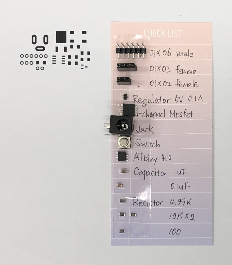
Choose Supporting Parts
I decided to use button as supporting part. Because I was going to program as follows.
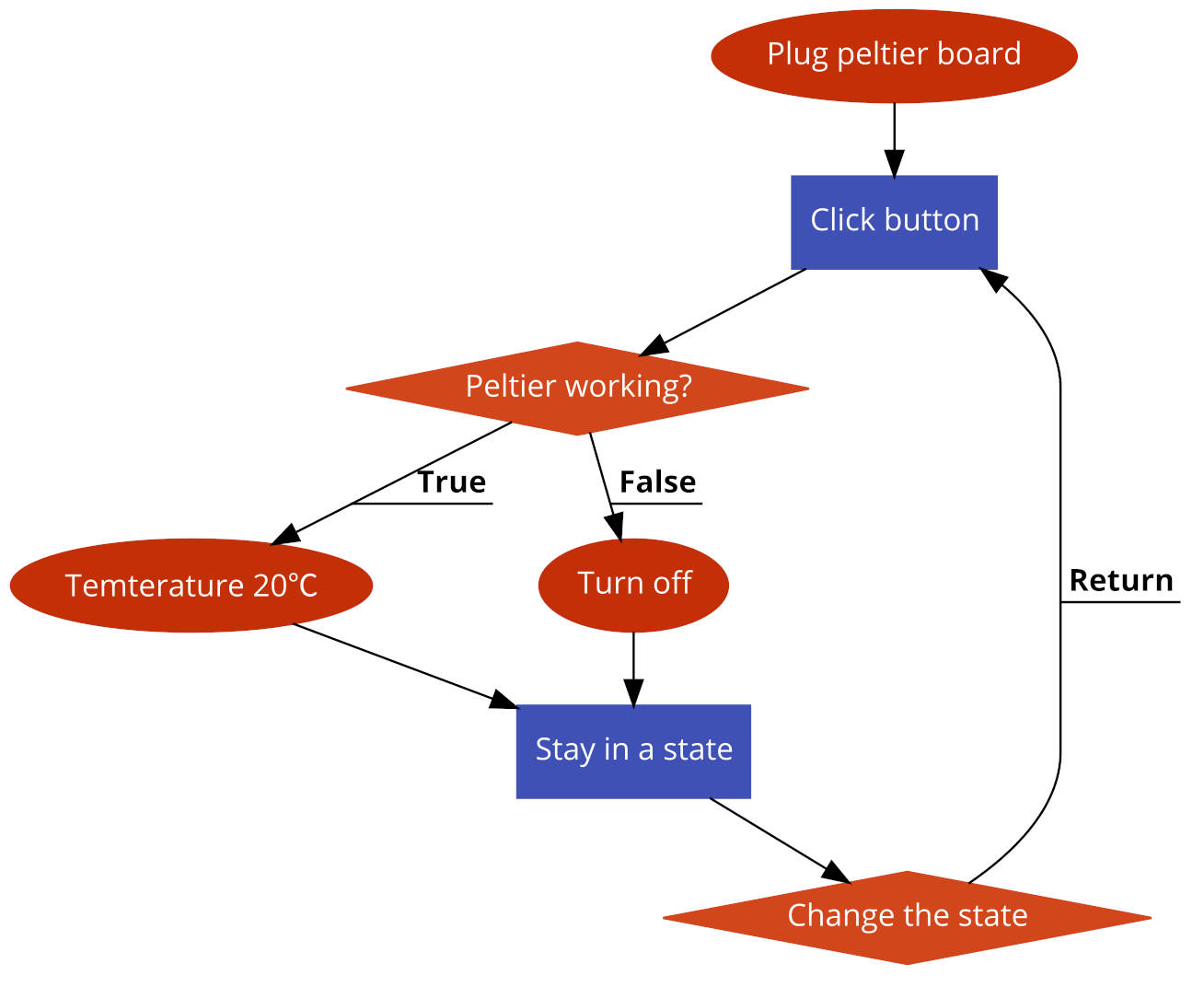
click button - increase temperature of the paltier heater to the temperature set
click button again - the paltier heater turns off
Follow Tutorial / Example
- First, I searched “peltier arduino tutorial" in google and found a tutorial by Ali Atwa.
- I was going to follow the tutorial and test the peltier module in Arduino.
- I needed an "N-channel Mosfet", but there was no "N-channel Mosfet" for the breadboard here. So I decided to make a board right away.
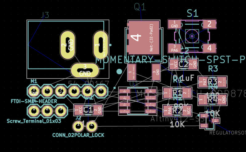
Provide Schematic Diagram
Q. What is the difference between n-channel and p-channel mosfet?
The hole mobility is nearly 2.5 times lower than the electron mobility. Thus a P channel MOSFET occupies a larger area than the N channel MOSFET having the same ID rating.
Reference Site
Difference Between N Channel and P Channel MOSFETs
When is it good to use N MOSFET and when do you use P MOSFET?
Q. We had several N-channel Mosfet. But I didn’t know how to choose a N-channel Mosfet I need?
The Mosfet should have a higher value than the output device.
Check value of ouptup device
Check value of mosfet device
- Read datasheet about Output device.
- Checked "Rate Voltage", "Max Voltage", "Max Current" in peltier module datasheet. (For these, I referred to the following pictures.)
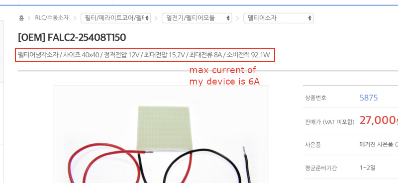
- Above items were compared with "Drain to Source Voltage", "Drain to Gate Voltage", "Continuous Drain Current" of N-channel Mosfet we had.
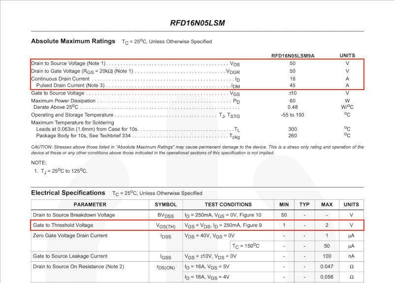
So I choose this mosfet RFD16N05LSM9A.(RFD16N05LSM9A Dataseet)
About Gate to Threshold Voltage
- Furthermore, it even confirmed "Gate to Threshold Voltage" in the picture above. It is the voltage of the signal that the Mosfet receives for the output device. The mcu I choose had to be able to send at least as much current as it does.
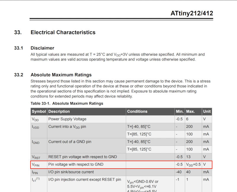
- Gate to Threshold Voltage of Mosfet is 2V. So I needed MCU, which can send current more than 2V. (Here is ATtiny412 datasheet)
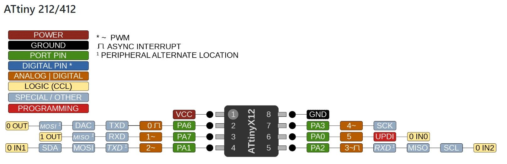
All I know is that it uses fewer pins than ISP and is up to date. and need UPDI programer for using UPDI.
When my instructor checked Schematic Diagram, I get some flaws.
Before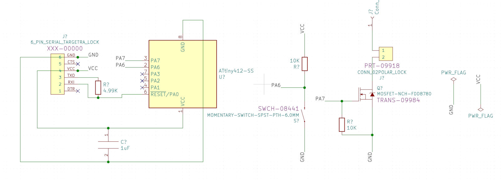
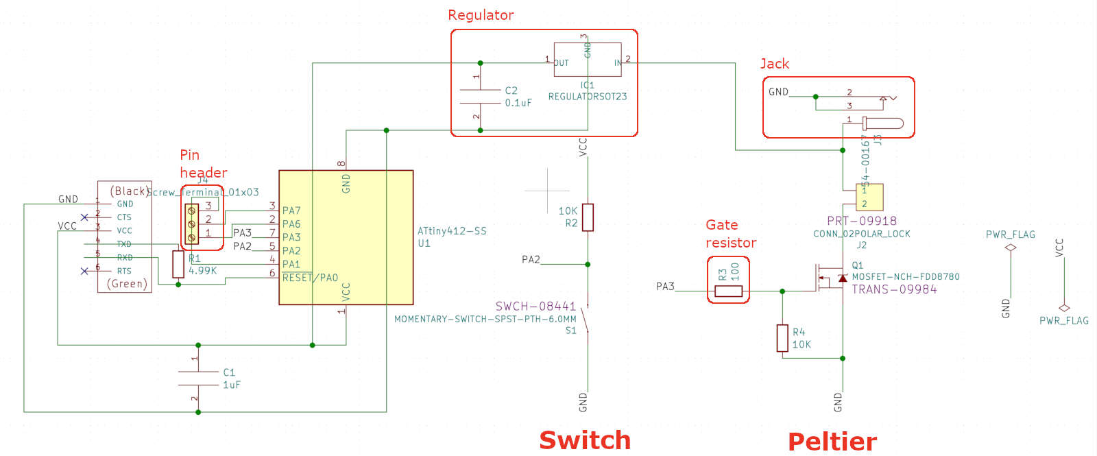
- The resistor shall be inserted between the pin and the mosfet.
Q. What is the MOSFET?
MOSFET is a voltage controlled device. It is mostly used in electronics circuits as switching and amplifier.
Q. Gate Resistor = Load Resistor???
Yes, Gate Resistor = Load Resistor.
Q. What is the role of gate resistor?
One reason a gate resistor is used is to slow down the turn-on and turn-off of the MOSFET. (This is more relevant to power circuits that switch a fair amount of current.) While it may seem that very fast switching is desirable, because of lower switching losses, it can result in ringing due to parasitic inductances, leading to electrical noise problems.
Q. How is the value of the resistor connected to mosfet determined?
Two resistors are connected to the mosfet, one is a gate resistor and one is a pulldown resistor. A typical gate resistor value would be a few ohms to a few dozen ohms. And the typical pull-down resistor value is 1-10 kΩ.
- There is no current flow circuit for MCU to receive.
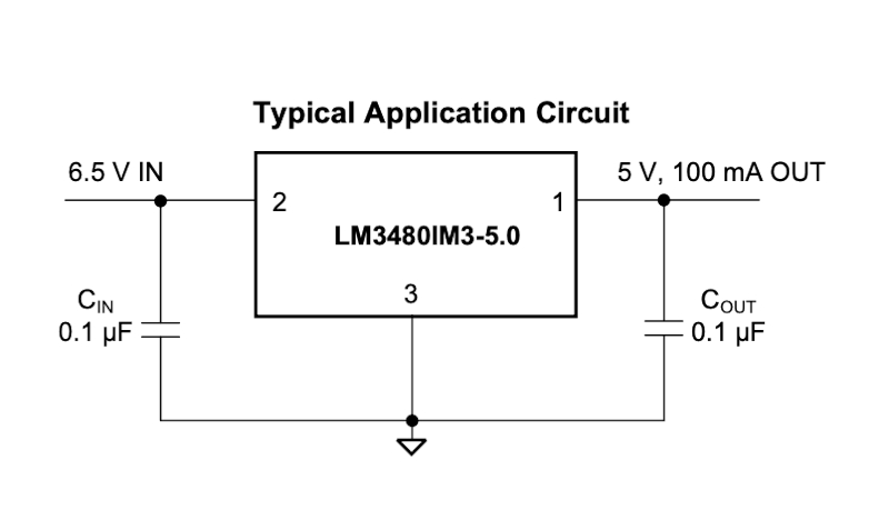
For Vsource to power the MCU after the program is inserted, 12V(Vsource) needs to be converted to 5V for MCU, which requires a regulator.
Q. Which regulator should be selected?
It shall be possible to convert 12V to 5V and to know the required current value in the circuit. As MCU will mainly assign current, check the supply current of ATtiny412 datasheet.
So I chose the 5V 0.1A regulator. It is LM3480. When I checked LM3480 datasheets it was allowed from 0V to 30V, and needed Cin and Cout.
- The schematic of 12V power was changed. So I searched “jack” in “Snap EDA” site.
- In addition, I connected the pins of ATtiny that are not in use now to a pin header socket for later use.
Q. Should Jack's two gnds be connected?
Doesn't matter.
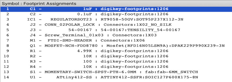
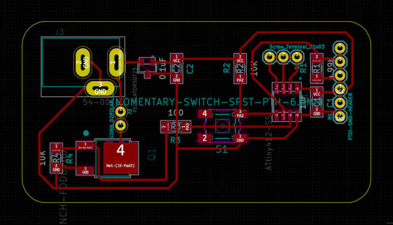
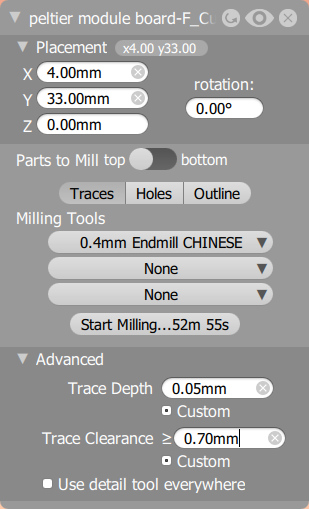
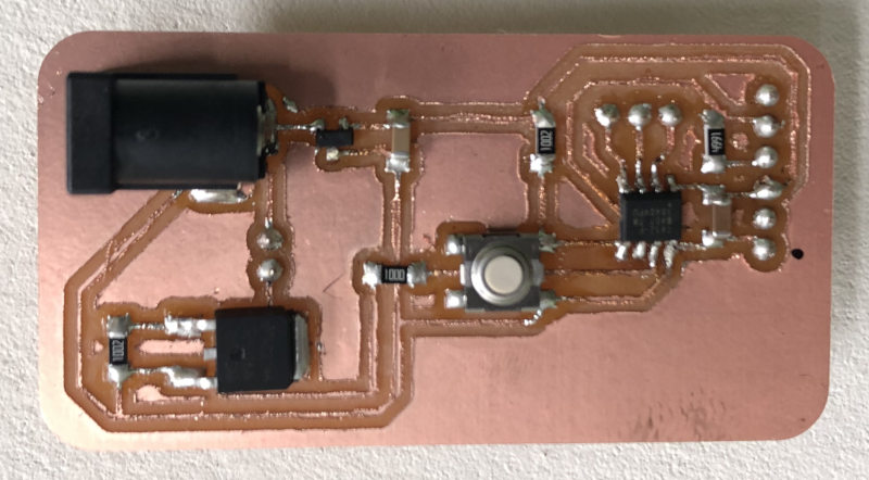
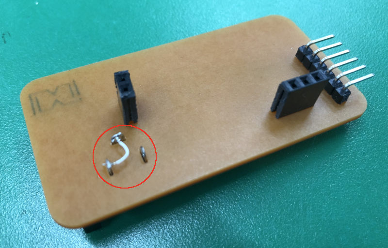
Milling and Soldering
I followed the workflow of the week4.
Programming
- First, I found "UPDI programmer software for Arduino" to use the Arduino board as an UPDI programmer and uploaded "JICE_io.cpp" code. (site of UPDI programmer software for Arduino)
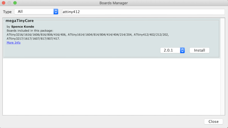
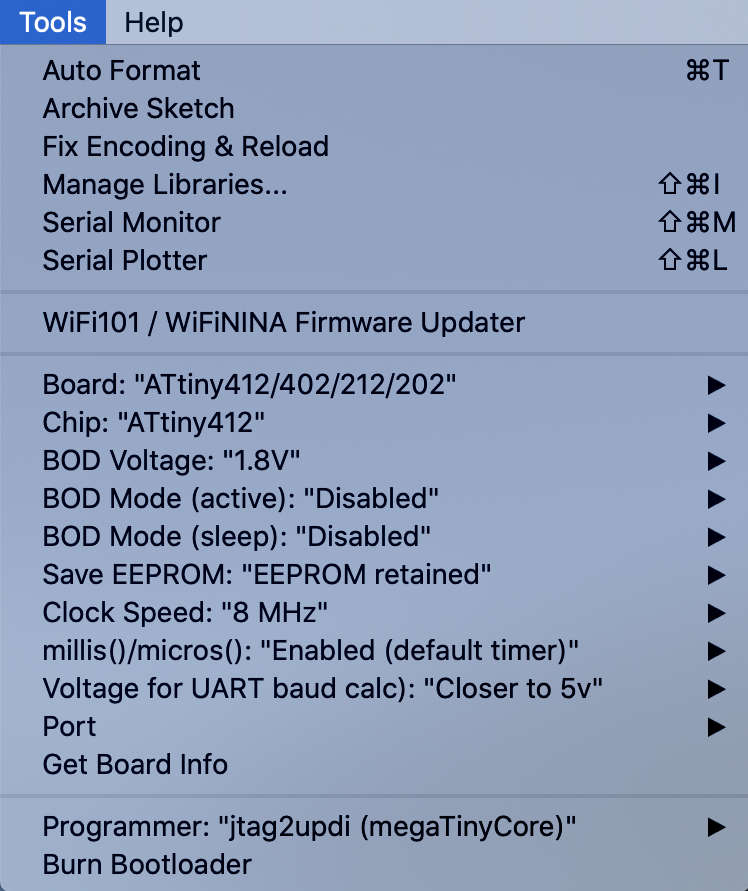
- In the tool - board manager, I found and downloaded the core for ATtiny412, set it as below, and put the code.
- The code was referred to the code on another tutorial site.
Arduino Code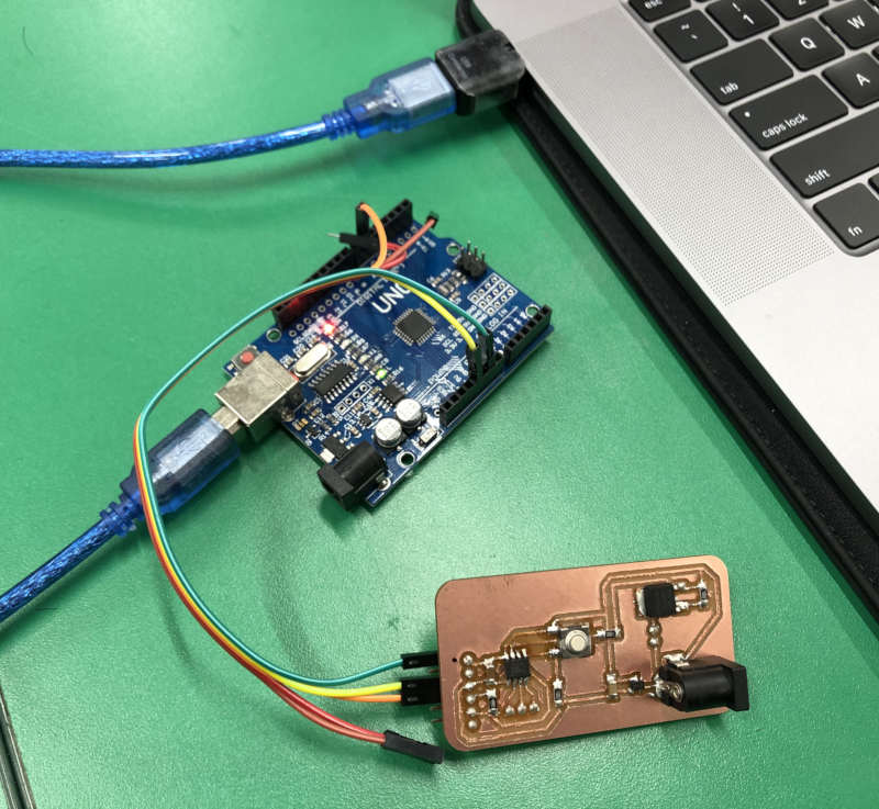
int buttonPin = 2; int buttonInput = 1; int buttonState = 0; int peltier = 3; void setup() { pinMode(buttonPin, INPUT); } void loop() { buttonInput = digitalRead(buttonPin); if (buttonInput == 0) { if (buttonState == 0) { buttonState = 1; } else { buttonState = 0; } delay(500); } if (buttonState == 1) { analogWrite(peltier, 120); // Look first on how much voltage your peltier unit can handle 255 = 5V } else { analogWrite(peltier, 0); } delay(500); } - But the peltier connected to my board didn't work, I used a multimeter to find some problems.
Problem 1
The problem was that the current flowing to my board was 0V because I didn't solder the gnd connected to the jack.
Solution 1I wired the two pins of the jack.
 Problem 2
Another problem was that the regulator didn't work.
Solution 2So I swapped the regulator with a new one and the problem was solved.
Problem 3Next problem was ATtniy, which connected two VCCs in the process of verifying the regulator's operation, and probably ATtiny died and was unable to insert the code.
Solution 3ATtny was replaced and the problem was solved as well.
Problem 4Final problem was, although the code was inserted, the phenomenon of the regulator continuously getting hot. Even though I only connected the programmer and my board, my regulator got hot.
Solution 4The regulator plays a role in lowering the external Vsource, and if you connect with the programmer's vcc to insert the code, a short can occur. - Saverio said, In regional review
So when I put in the code, my board had to be powered by an external Vsource without a programmer's vcc.
Problem 5There was a problem with my code
Solution 5So I changed the "blink" code in arduino example a little and tested it.
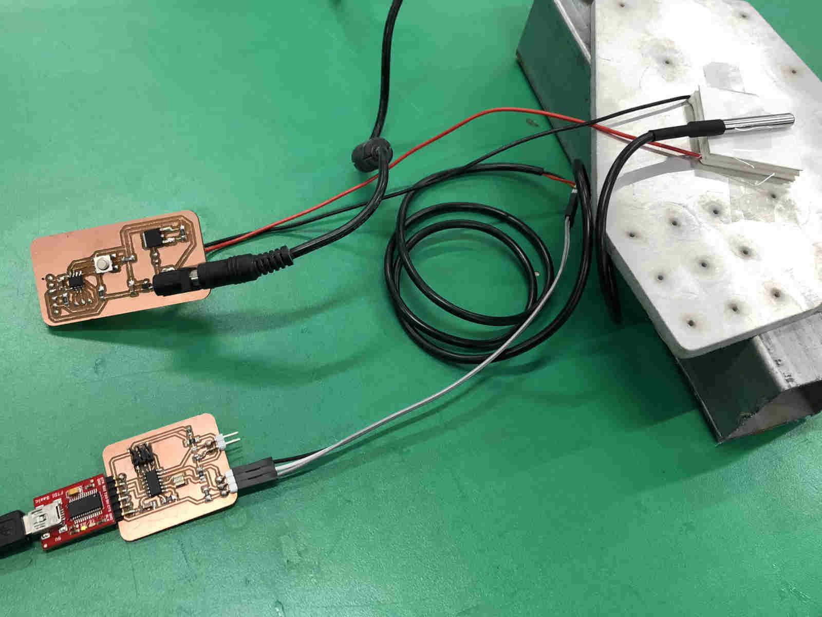
Modified Blink Codeint mosfetpin = 4; // the setup function runs once when you press reset or power the board void setup() { // initialize digital pin LED_BUILTIN as an output. pinMode(mosfetpin, OUTPUT); } // the loop function runs over and over again forever void loop() { digitalWrite(mosfetpin, HIGH); // turn the LED on (HIGH is the voltage level) delay(3000); // wait for a second digitalWrite(mosfetpin, LOW); // turn the LED off by making the voltage LOW delay(3000); // wait for a second } - The peltier module worked well and I measured its temperature using the temperature sensor board made during input devices week.
Video