Computer Controlled Machining
Computer Controlled Machining
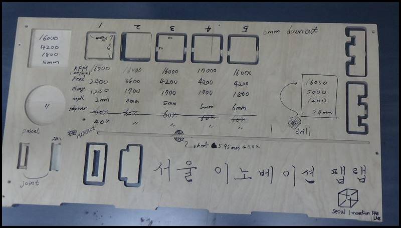
Result Value
| Material/Endmill | 12mm Plywood / 6mm downcut endmill |
|---|---|
| Feed Rate (mm/min) | 3600 |
| Plunge Rate (mm/min) | 1700 |
| Spindle Speed (rpm) | 16000 |
| Stepover (%) | 40 |
| Cut Depth (mm) | 4 |
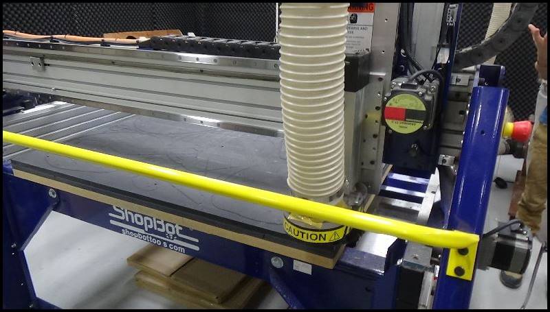
Test runout, alignment, speeds, feeds, and toolpaths for your machine
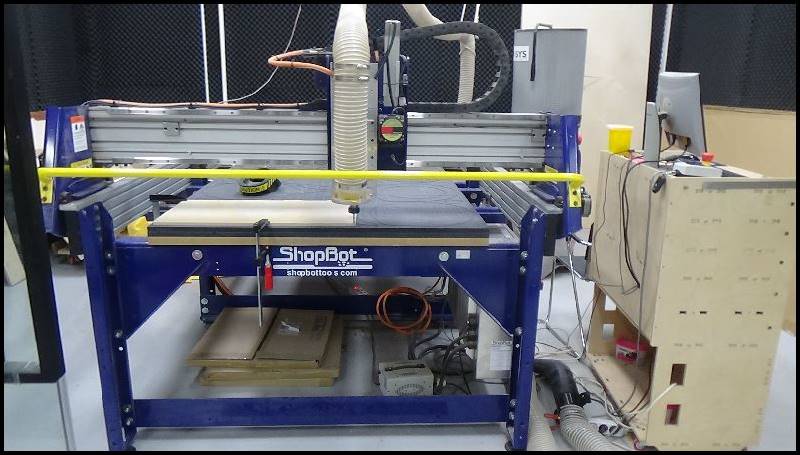
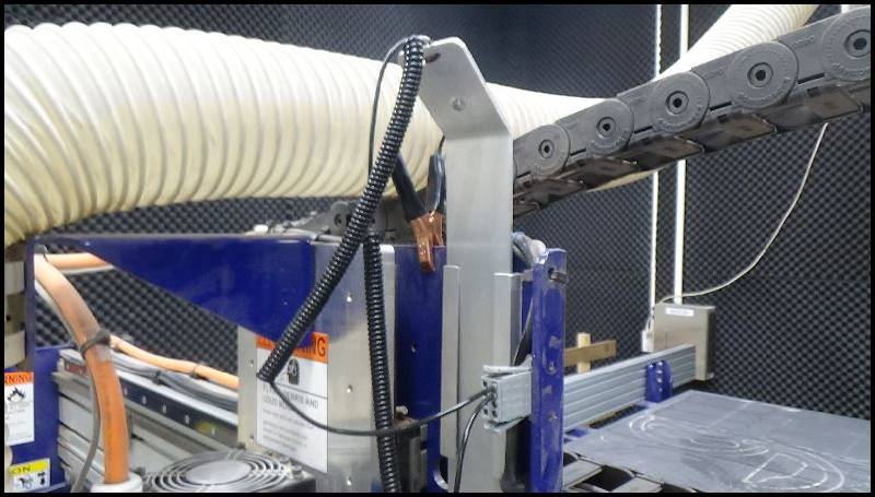
We use shopbotPRSalpha Shopbot specification
It can cut upto 2440 x 1220 mm. We use “V-Carve” software.
Before you screw it up to fix the plywood.
Fix it with a wood clamp.
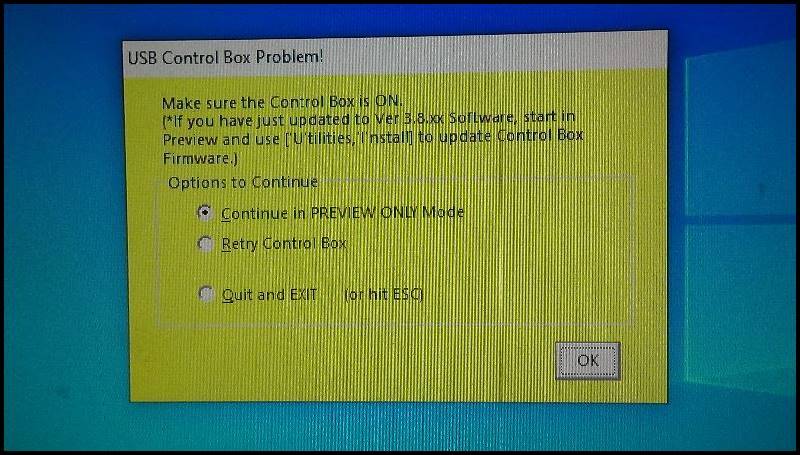
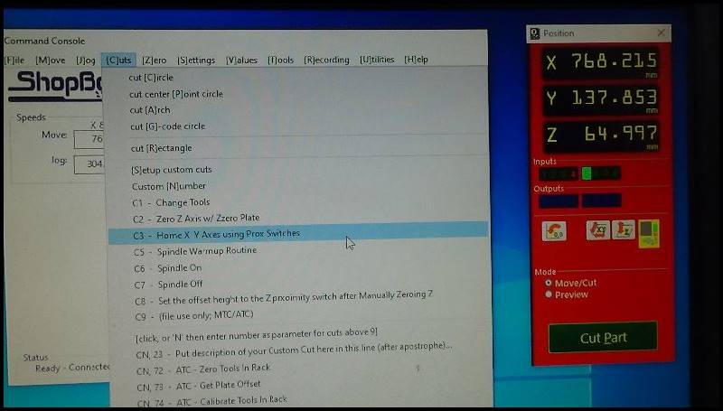
It appears when the control box is not turned on when we turn on the machine (ShopBot) as a warning message.
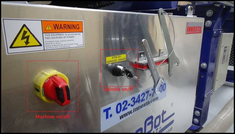
This is the control box.
Machine on/off – Spindle on/off.
To turn on, turn it to the right side (clock-wise).
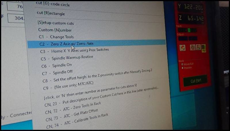
This is the command for zeroing out both x-axis and y-axis, setting the origin.
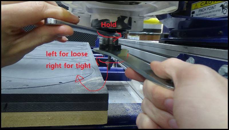
This shows how to put on/off the endmill.
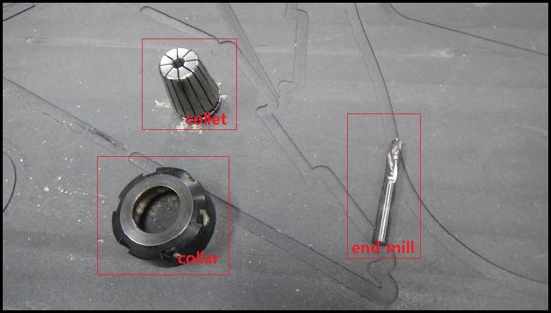
“Collet Assembly” – These are the tools for ShopBot.
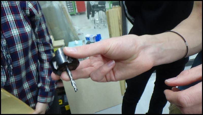
Use one finger to hold the endmill when putting it inside the hole of collet, and then assembly the three components (Endmill, Collet, Collar).
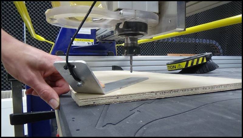
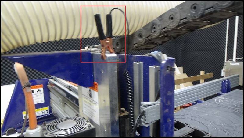
This is how we zero out z-axis. (Electricity and Two metal tools used.)
All is set for the origin.
The two tools for zeroing out the z-axis should be put back to their place.
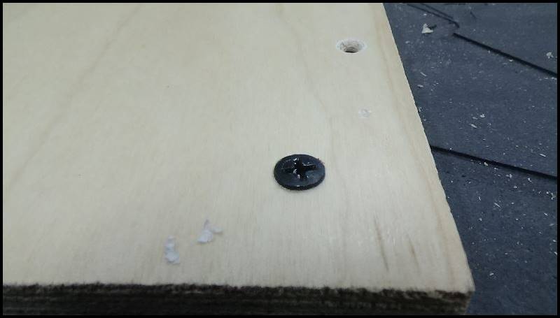
To fix the material on the machine bed, we have made a little footprint for the screw to be placed.
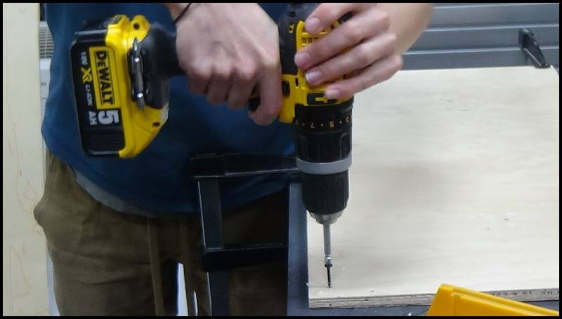
A good example of using the drill for putting the screws. Be perpendicular!
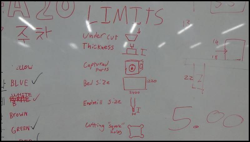 These are what CNC is not capable of doing. Limits.
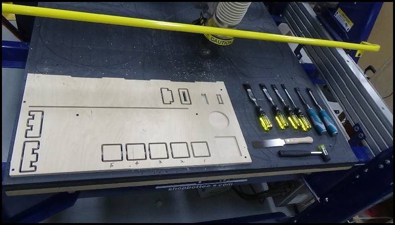
Tools for getting rid of tabs around what’s been cut.
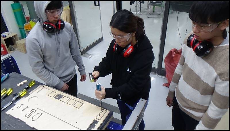
A classmate is getting rid of the tap around a joint.
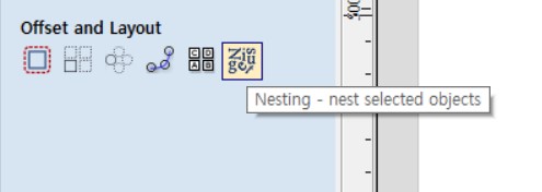
Use the Nesting feature to sort design files
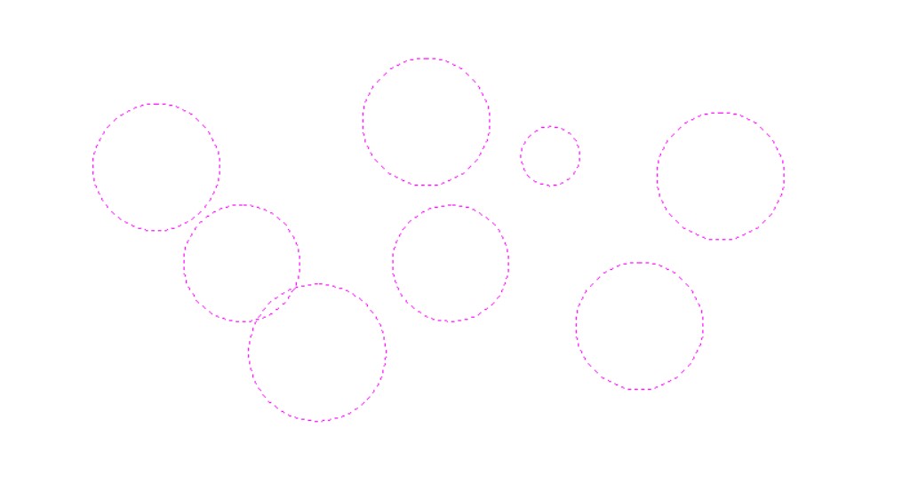
Before Alignment
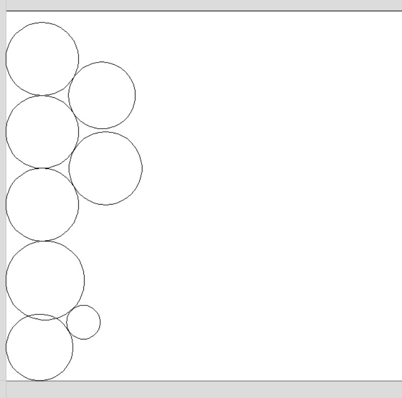
After alignment Alignment functions save material, but manual placement is more effective or
The solution described by student Kim Ji-hwan
And the alignment was fine
Profile ToolPath - Toolpath used to cut objects
Pocket ToolPath - Toolpath used to dig out objects
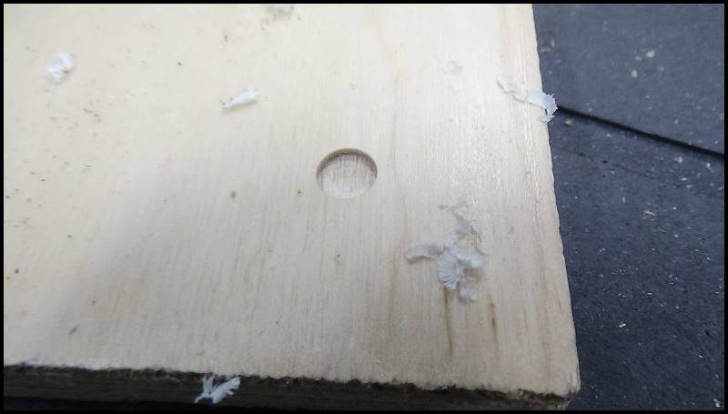
Drilling ToolPath - Tool path used to drill objects
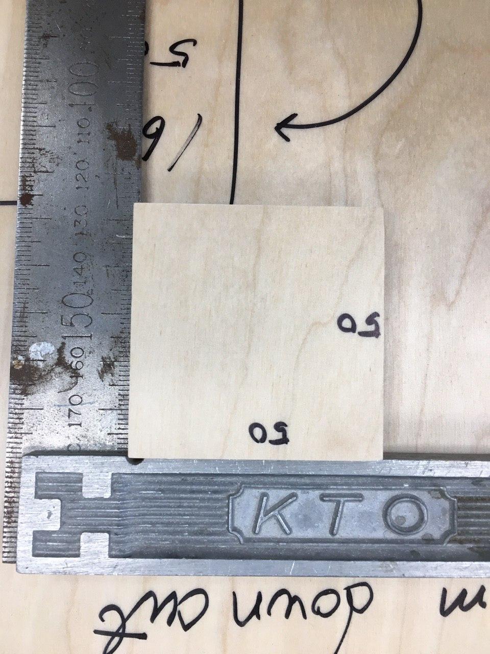
tolerance and clearance - The generation of tolerances during processing of end mill varies depending on the type of blade, number of blades, diameter size, collets, foreign substances, and the settling/horizontal nature of CNC equipment. Therefore, the joint must be machined 0.3 to 1.5mm more than the number you intend to process
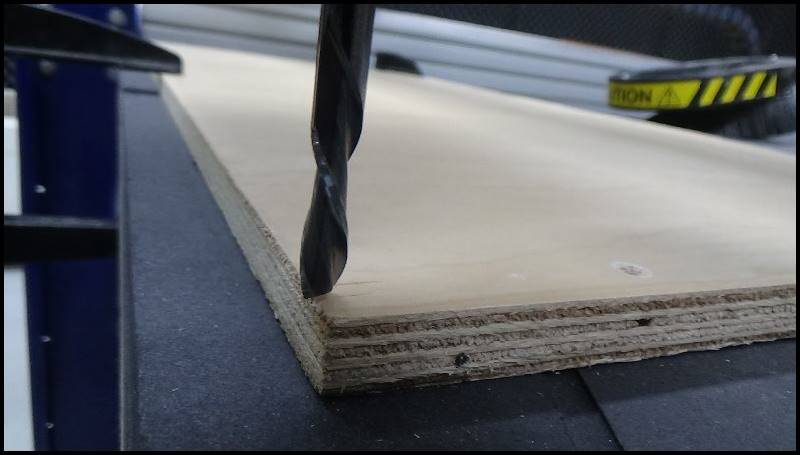
(Birch plywood 12 mm thickness used.)
(6 mm down-cut endmill used.)
What we have realized after our experiment:
- Profile Cut:
The most effective (time-wise and quality-wise) is RPM 16000 mm/min, Feed Rate 3600, Plunge Rate 1700, Cut Depth 4mm, and Step Over 40%. - Run Out:
The overall width has a range of 5.95-5.97mm, meaning that it was accurate, being close to 6.00mm. - Pocket:
It would be a lot neater if we would have reduced the Feed Rate. - Joint:
We have designed the joints without any kerfs, and after we cut, we found out that the joint components could not fit into one another without using a hammer. Therefore, we should set some kerfs values when we cut something again later. We have not found the exact result-value, which we will individually discover later.