Electronics Design
Group Assingment
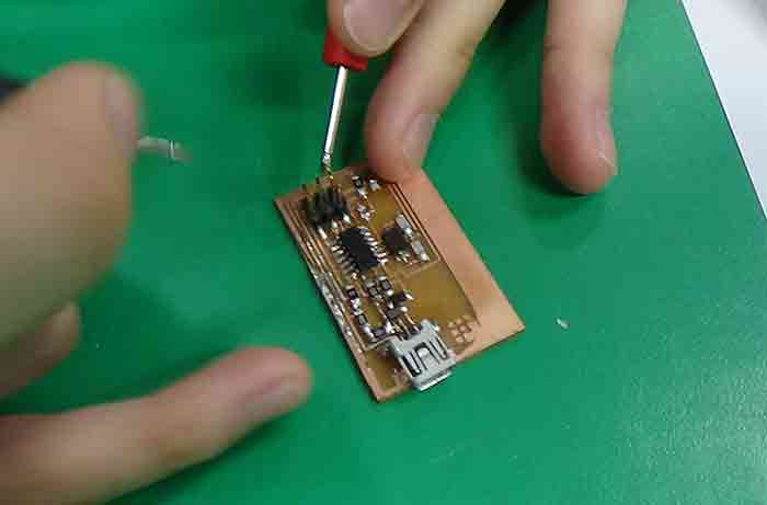
Use the test equipment in your lab to observe the operation of a microcontroller circuit board
Our Process
1. Testing Equipment :
1. Multimeter – when measuring R (resistance – Ohm)
2. Multimeter – when measuring A (Current – Ampere
3. Multimeter – when measuring V (voltage – Volts)
4. Oscilloscope –- graphs V over time (voltage – Volts)
5. Regulated Power Supply – supplies V (voltage – Volts)
6. DC/AC Clamp Meter
7. Logic Analyzer (useful for sending signals between two chips)
2. KiCad Process :
1 ) Download libraries: sparkfun, fab, digikey, OPL-made by “seeed” company by Jessy.
2 ) Open kicad and make a file
3 ) Find the reference image for the circuit board design (file name: hello echo)
4 ) Find, add all the component
5 ) Google/search “arduino [component name] sch”, and find the most effective design
6 ) Add LED / switch / extra part (to add extra functionality)
7 ) Design the circuit board
8 ) Refer to the pinout reference image (for layout)
9 ) Label the resister’s capacity value (e.g. 1k, 10k)
10 ) Annotate each component on the circuit
11 ) Check for the errors(rule check)
12 ) Assign footprint
- model name of the microcontroller: 1206
- model name of the [ ]: SOIC8
- important to double click before closing the footprint screen
13 ) Generate, save the net file
14 ) Open the black screen called “pcbnew”
15 ) Open the netlist file that we’ve saved on the white screen called “schematic layout”
16 ) Rearrange the components (so that not too many components cross over each other)
17 ) Connect the components using the red line called “Route tracks”
18 ) Check if there’re any errors
19 ) Make outline using “edge.cut”, “graphic line”
20 ) And hole
21 ) “Edge cut”
22 ) Open the print setting, and only plot: “f.cu” and “edge.cuts”
23 ) Print the finished design on A4 paper (to see if it matches the size of the actual physical component)
24 ) Generate drill file
25 ) gnd/vcc/isp/microcontroler don’t short
26 ) google the model name/number of the component addes (e.g. switch, led)
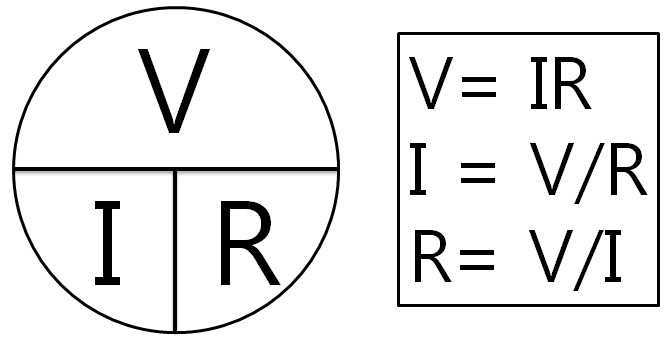
Key Formula
V = voltage, I = current, and R = resistance
The current flowing through the conductor is proportional to the voltage and inversely proportional to the resistance
1. Multimeter – when measuring R (resistance – Ohm)

-
Black = COM, Red = VΩHz
-
Continuity test – useful for checking the connection (Beebs when trace connect)
-
Important:
To always test:Check the (+) and (-) do NOT connect.Check the beginning and the end of (+)CONNECT. Same goes to (-).
- % value shows accuracy
The lower the better. (The lower the greater accuracy)Used when checking R (resistance -- Ohm)
-
Measurement (how to read the number)
Milli < Ohm < k-Ohm < M-Ohm
2. Multimeter – when measuring A (Current – Ampere)
-
Black = COM, Red = 20A
-
Measures current through the multimeter
-
DC Current
-
Don’t exceed max rating
-
Can change scale
However, there are not many options for choosing the scale200mA20ASomething in-between might not show up (number) on the screen, and this will appear as "zero" instead of the actual value.
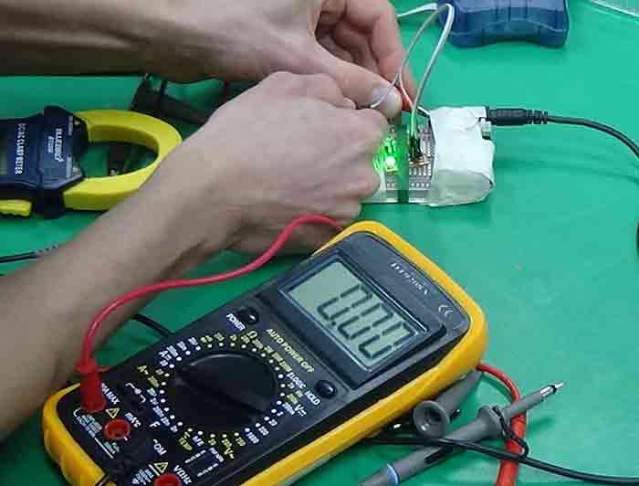
3. Multimeter – when measuring V (voltage – Volts)
-
Black = COM, Red = VΩHz
-
In Fab Academy, we predominantly work with low voltage DC - not AC - due to safety reasons
- Background voltage noise in the air means nothing.
Important:To always work in the "voltage range".Otherwise, the graph will not show up on the screen.
- Every time the light blips, there are changes in graph.
It means that there are changes in voltage every time the light blips.→ Therefore, "Multimeter is bad for testing anything fast, such as light."→→ INSTEAD, we have "oscilloscope"! -- described and explained below.
- Etc
When we measure the voltage across the vcc & gnd lines it was 4.8V. Many microcontrollers can’t tolerate more than 5V. If you give voltage more than 5V to input pin of the microcontroller, it will get damage permanently.
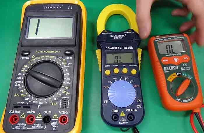
Q. Why do we have more than one type of multimeter?
→ There are a range of options:
1)Some are relatable to you -- a particular person -- and your level of knowledge about it
2)The others are robust and difficult to use; they have specific usage.
→ In a big picture, in Fab Lab, we have a range of ways to solve a problem/question. And that’s the learning process when it comes to almost anything, especially engineering, computer science, design, etc.
→ Therefore, we have various kinds of multimeters.
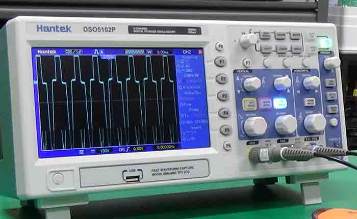
4. Oscilloscope
-
How to use it:
1. Set the default setup
2. Plugin the lines, and activate them by pressing the corresponding buttons
3. Attach my "grounder(s)" (By doing so, the background noise is cancelled out.)
Ref) Everything adds up to zero (The Law of Thermodynamics applies.)
4. Adjust the line is always showing up on the screen. (To do this, turn the "horizontal" and "vertical" buttons around until you can see the graph in the appropriate scale.) - Longer time period (Longer “MS (unit)”): we can see the changes in voltage more easily.
ImportantTo get rid of background noise (unwanted voltage)→ Refer to the number (3) above!
-
Super useful:
Because we can measure multiple lines at the same time.
-
There is an extra setting section on the screen:
- We can change the scale of the grph on the screen.
-
f (Frequency) is useful for audio-related stuff (e.g. radio, light with movement)
- “Measure” button shows “volts” value
- Plus
Q. How to measure logic and pwm signals by using the Oscilloscope?
→ We tried it at the group assignment of Input Devices Week.
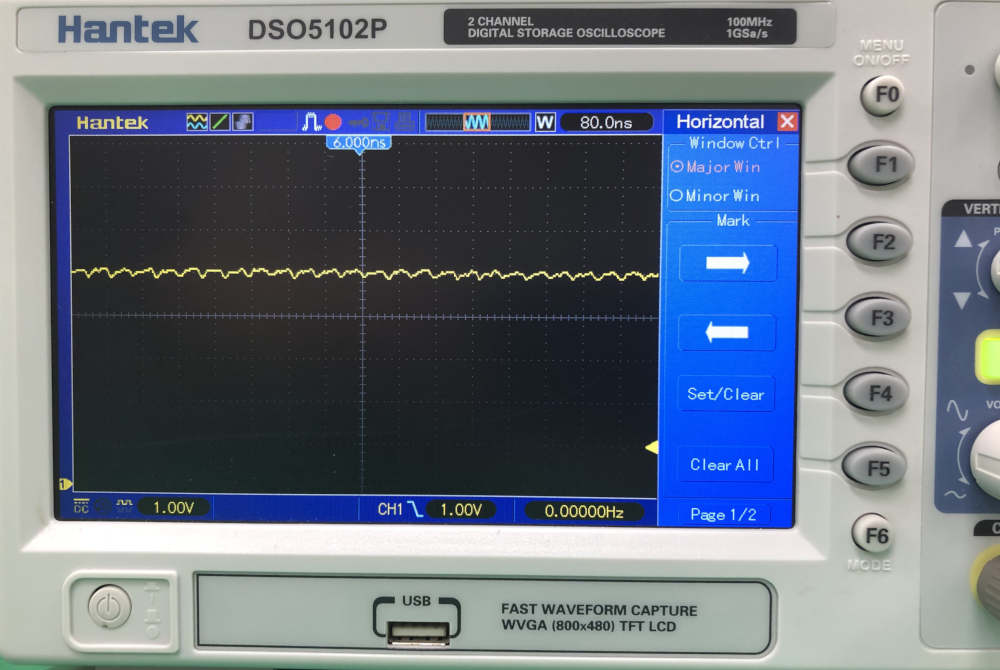
- When we use the oscilloscope to measure the VCC line on one of boards
We could see the noise as below.
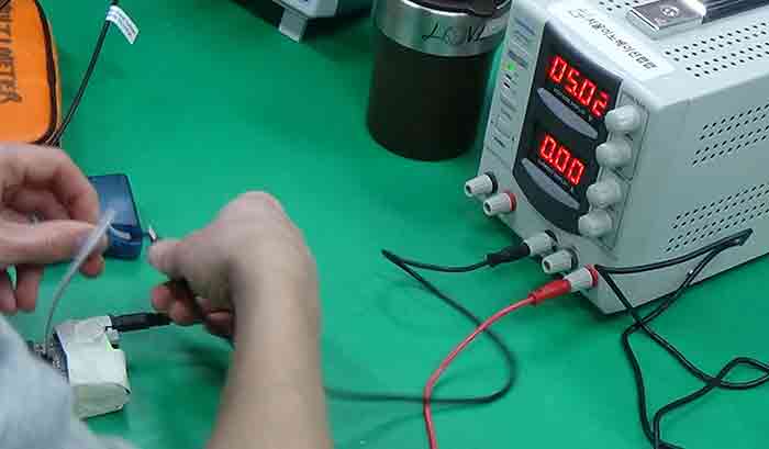
5. Regulated Power Supply
-
There are five holes at the bottom of this equipment:
-
The left two: Their output is always 5 Volts.
Q. Why is it always 5V? Let’s find out why!
-
The right three holes: Their output can be set and change. (customizable)
- Power flows from (-) to (+)
- Red = (+)
- Black = (-)
- CC and CV
- CC = Control Current
- CV = Control Voltage
-
- Plus
The equipment (Regulated Power Supply) is more important when testing “motors.”
Just DC
Because AC might cause some safety issues.
Because AC electronics require certain certification to work with it.
(refer to: Korena Agency for Technology and Standards (<http://www.kats.go.kr/main.do>)
6. DC/AC Clamp Meter ?
It is used for checking R (resistance – Ohm) Useful for measuring/dealing with big or huge values
7. Logic Analyzer (reading signals sent between two microcontrollers)
One of the other extra tools