Networking And Communications
Networking And Communications
Wifi(seokmin, Yunjo)

Code
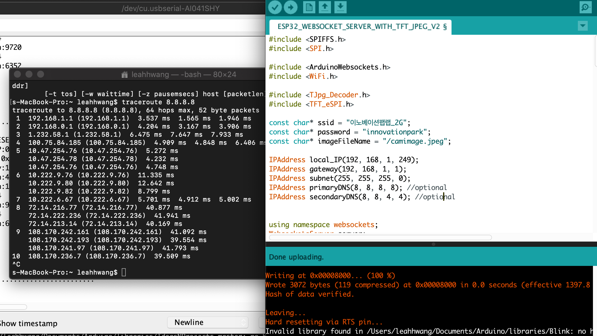
The following code was generated to connect the WIFI network
const char* ssid = “이노베이션팹랩_2G”;
const char* password = “innovationpark”;
const char* websockets_server_host = “192, 168, 1, 249”;
const uint16_t websockets_server_port = 8888;
IPAddress local_IP(192, 168, 1, 249);
IPAddress gateway(192, 168, 1, 1);
IPAddress subnet(255, 255, 255, 0);
IPAddress primaryDNS(8, 8, 8, 8); //optional
IPAddress secondaryDNS(8, 8, 4, 4); //optional
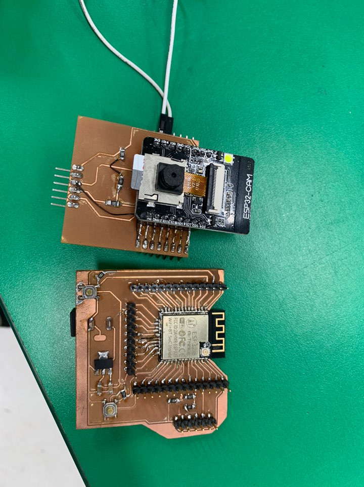
- We succeeded in connecting the ESP32-CAM board with the ESP32-S board to Wi-Fi.
- Enter the correct Wi-Fi name and password to use.
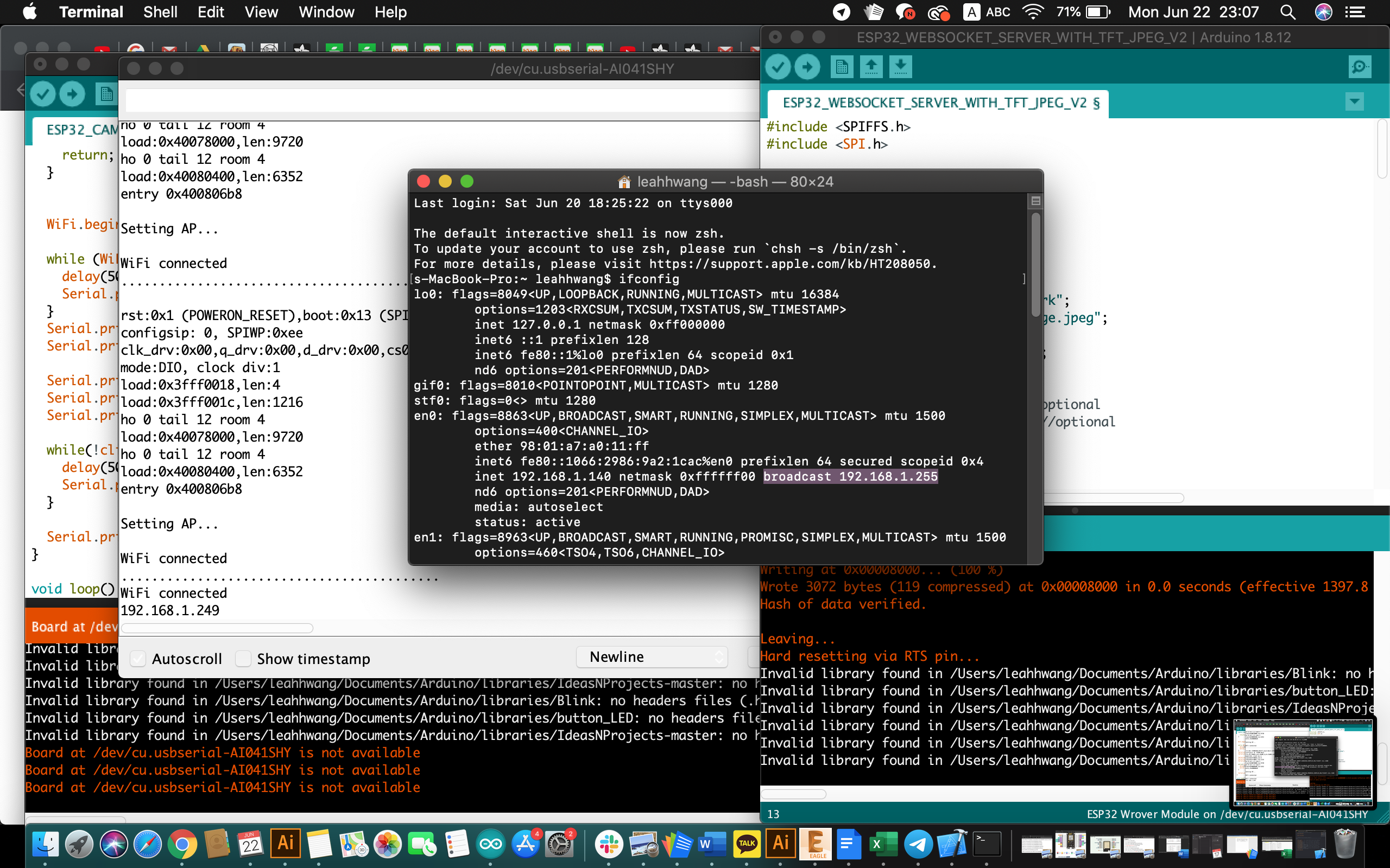
- When one Wi-Fi is connected, put the address that comes out of the other board as const char* websokets_server_host = “Adress.Adress.Adress.Adress.Adress”.Adress.”
- The server port is set at 8888.
- IPAddress local_IP(192, 168, 1, 249); <—— Even if you do the above process, Resetting the board can cause it to be issued a different address. So, to fix the address of the host board, you enter it in this code.
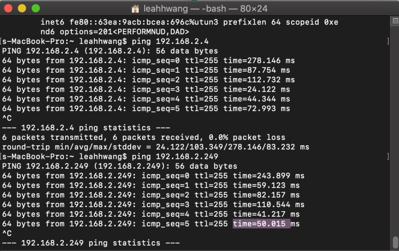
- You can view the Wi-Fi connection status by entering tracerout 8.8.8.8 at the terminal.
BLE(Jeonghwan, Hyunho)
Communication With Cell Phones And Arduino
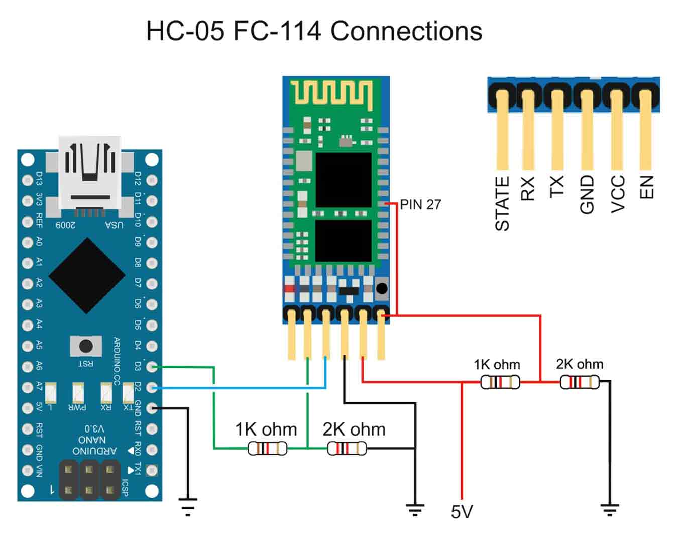
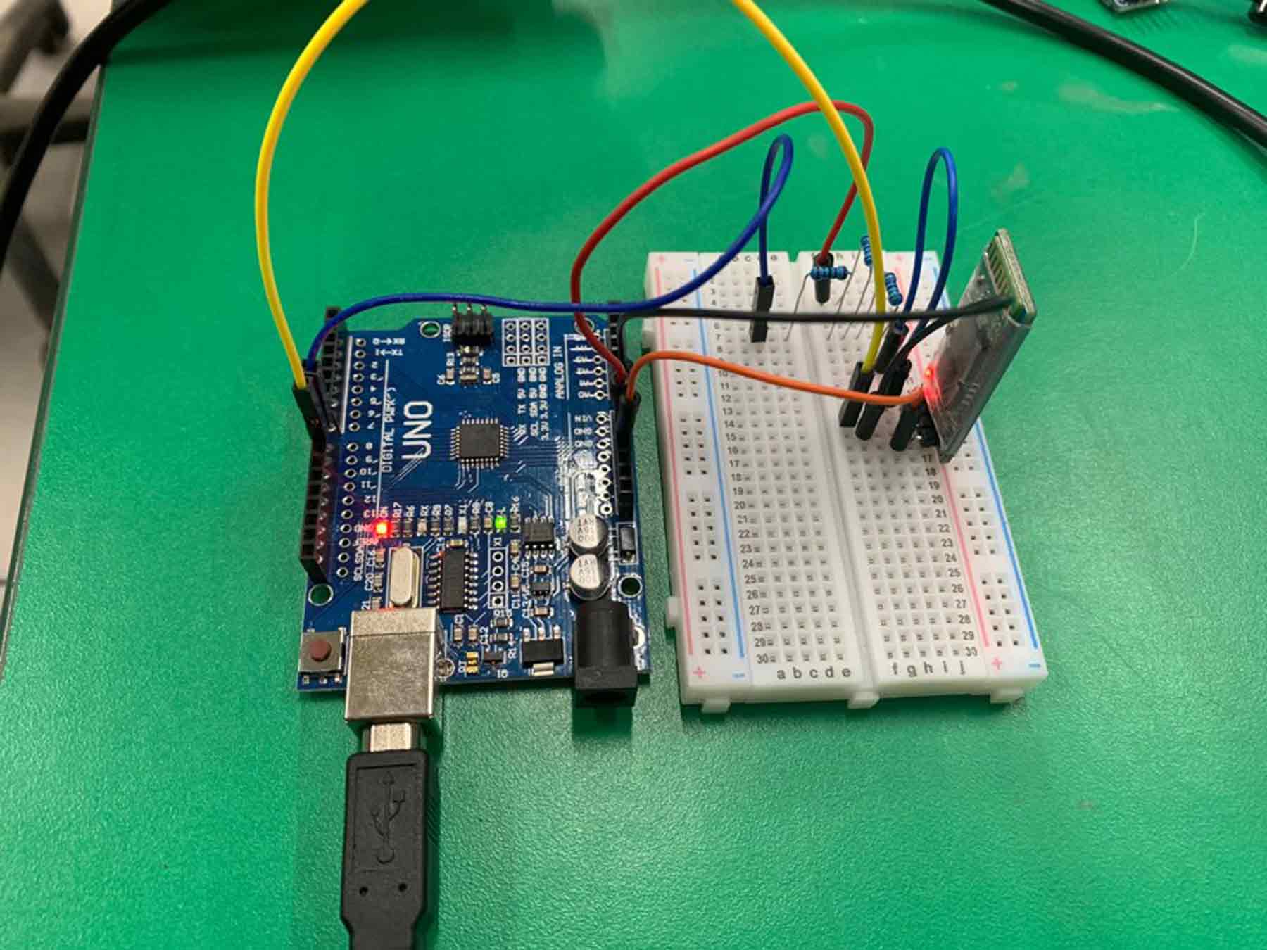
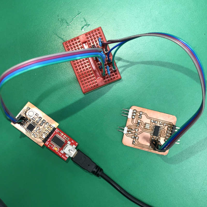
First, prepare bluetooth dongle, breadboard, Arduino board, jumper wire and three 1K register.
And connect the supplies by referring to the picture below.
The HC-06 is a slave only BT module that is fairly easy to use with the Arduino using serial communication. Once it is connected it simply relays what it receives by bluetooth to the Arduino and whatever it receives from the Arduino it sends to the connected device. There are several slightly different versions of the HC-06, however, all seem to use the same firmware and have the same AT commands. The ones I have are labelled as zs-040. I also have some HC-05s which share the same PCB and are also labelled as zs-040.
Connections
The Bluetooth module the ZS-040 is based on, the EGBT-046S, is a 3.3V device. The HC-06 breakout board has a 3.3v regulator that allows a larger input voltage to be used, in the range of 3.6 to 6 volts. The RX pin can still only accept 3.3V though. This means a voltage divider is required to connect to a 5V Arduino. A simple voltage divider can be created using 2 resistors. I am using a 1K ohm resistor and a 2K ohm resistor. The Arduino will read 3.3V as a HIGH so the HC-06 TX pin can be connected directly to the Arduino.
HC-06 Vin to 5V (can be from the +5V out from the Arduino) HC-06 GND to common GND HC-06 RX to Arduino pin D3 (TX) via a voltage divider HC-06 TX to Arduino pin D2 (RX) connect directly
Insert the Arduino code into the board, which is designed for Bluetooth communication.
#include <SoftwareSerial.h>
    SoftwareSerial BTSerial(9, 8); // RX | TX
    char c=' ';
    boolean NL = true;

    void setup()
    {
        Serial.begin(9600);
        Serial.println("Sketch HC-0x_FC-114_01_9600");
        Serial.println("Arduino with HC-0x FC-114 is ready");
        Serial.println("Make sure Both NL & CR are set");
        Serial.println("");

        // FC-114 default baud rate is 9600
        BTSerial.begin(9600);
        Serial.println("BTserial started at 9600");
        Serial.println("");
    }

    void loop()
    {
        // Read from the Bluetooth module and send to the Arduino Serial Monitor
        if (BTSerial.available())
        {
            c = BTSerial.read();
            Serial.write(c);
        }

        // Read from the Serial Monitor and send to the Bluetooth module
        if (Serial.available())
        {
            c = Serial.read();
            BTSerial.write(c);

            // Echo the user input to the main window. The ">" character indicates the user entered text.
            if (NL) { Serial.print(">");  NL = false; }
            Serial.write(c);
            if (c==10) { NL = true; }
        }
    }
}
Then downloads and run the “Bluetooth Viewer” from Android phone.
Connect Arduino and cell phone by Bluetooth.(The password for Bluetooth Dongle was 1234.)
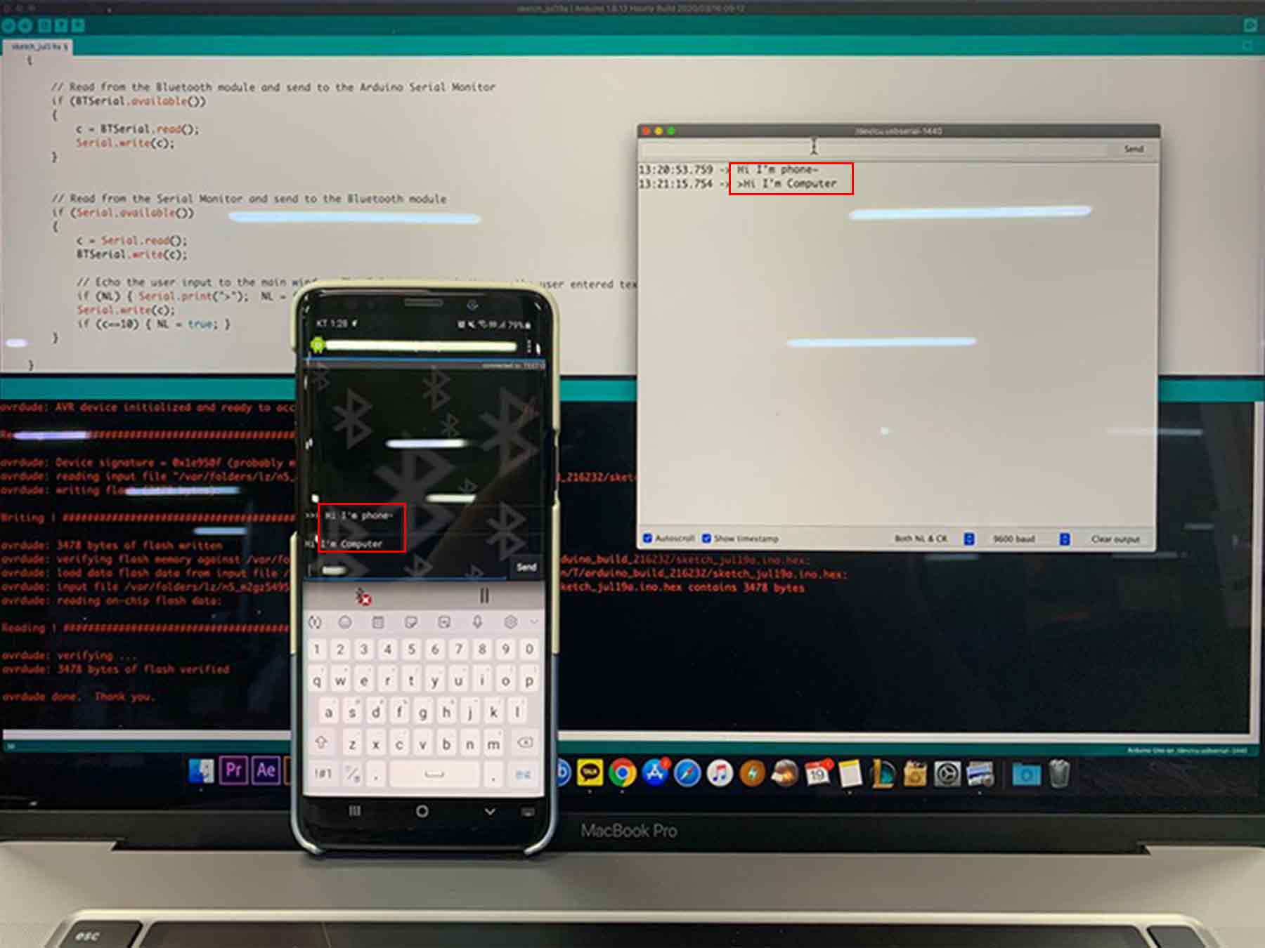
Communicate successfully.
Warning - Bluetooth Dongle should not exceed 3.3v, so the 1k register should be well connected as shown above.
Trial and Error - The rx of the Bluetooth Dongle must be connected to the tx of the Arduino Board, and the rx of the Arduino Board must be connected to the tx of the Bluetooth Dongle.If you don’t pay attention, the serial monitor won’t react and if you don’t, the dongle may break. (I spent 10 minutes wondering what the problem was because of this.)
In the final project - This time, I just communicated on a serial monitor, but in the final project, I decided to use “App Inventer” to create an application and connect the temperature sensor board to Bluetooth to check the figures.
I2C(Jihwan)
1. How I2C Networking Works & The Wiring Required To Form The Network
Briefly, it is a networking composed of a line (SDA) for sending and receiving data and a clock line (SCL) for synchronizing transport timing. Also, after each address is determined, information can be exchanged through the address.
2. Code I Used To Send Or Receive A Message
Master Board (ATtiny85 Hello Echo Board)
#include <SoftwareSerial.h>
#include <Wire.h>
SoftwareSerial mySerial(2, 1); // RX, TX
void setup() {
 Wire.begin();
 mySerial.begin(9600);
}
byte x = 0;
void loop() {
 Wire.beginTransmission(1);
 Wire.write("good ");
 Wire.write(x);
 Wire.endTransmission();

 delay(500);

 Wire.requestFrom(1, 4); //Request 4 byte to Slave (1)
 while (Wire.available()) {
   char c = Wire.read();
   mySerial.print(c);
 }
 x++;
 if(x==6)x=0;
}
Slave Board (ATtiny44 Input Board)
#include <SoftwareSerial.h>
#include <Wire.h>
SoftwareSerial mySerial(0, 1); // RX, TX
void setup() {
     Wire.begin(1); //slave address
     Wire.onRequest(requestEvent); //Invoke requestEvent function on demand
     Wire.onReceive(receiveEvent); //Call the reciveEvent function when data is sent
     mySerial.begin(9600);
}
void loop() {
     delay(500);
}
void receiveEvent(int howMany) { //Read Transfer Data
     while (Wire.available()>1) {
       char ch = Wire.read();
       mySerial.print(ch);
     }
     int x = Wire.read();
     mySerial.println(x);
}
void requestEvent() { //On-demand action function
     Wire.write("ok!\n");
}
Connection image
3. How I Know The Message Was Received Successfully
- If the board's Tx and Rx pins are available, we can debug using the Serial Moitor. (I mainly used this method.)
- To use I2C networking on the board, add a Wire.h library with
#includecode.(+ Wire.begin();) - And I added the SoftwareSerial.h library to use Serial above.(+SoftwareSerial mySerial(#, #);, mySerial.begin(9600);)
- When connecting the serial port to the master board in the above information, you can see the "ok!" message in the requestEvent content of the code on the slave board.
- And conversely, when you connect the serial port to the slave board, you can check the "good" and "x" messages between the BeginTransmission and the endTransmission of the master board.
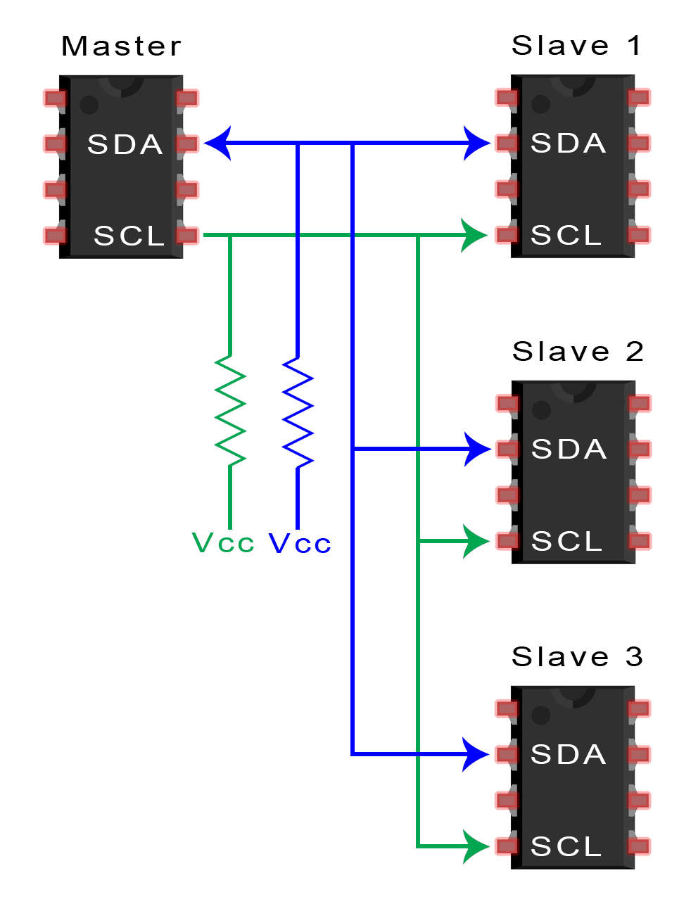
4. How do I plug them into 2,3 boards? (Reference Site)
Connect the SDL, SCL, GND and VCC lines of each board. (Like the breadboard I used)
To connect multiple slaves to a single master, wire them like this, with 4.7K Ohm pull-up resistors connecting the SDA and SCL lines to Vcc