14. Embedded Networking and Communications
Assignment
Group assignment
- Send a message between two projects
Group Project here
Individual Assignment
- design, build, and connect wired or wireless node(s) with network or bus addresses
Table of Contents
- How Bluetooth Works
- The Bluetooth protocol operates at 2.4GHz in the same unlicensed ISM frequency band where RF protocols like ZigBee and WiFi also exist. There is a standardized set of rules and specifications that differentiates it from other protocols. If you have a few hours to kill and want to learn every nook and cranny of Bluetooth, check out the published specifications, otherwise here's a quick overview of what makes Bluetooth special.
- Masters, Slaves, and Piconets
- Bluetooth networks (commonly referred to as piconets) use a master/slave model to control when and where devices can send data. In this model, a single master device can be connected to up to seven different slave devices. Any slave device in the piconet can only be connected to a single master.
Master/slave topology
Examples of Bluetooth master/slave piconet topologies.
The master coordinates communication throughout the piconet. It can send data to any of its slaves and request data from them as well. Slaves are only allowed to transmit to and receive from their master. They can't talk to other slaves in the piconet.
- Bluetooth networks (commonly referred to as piconets) use a master/slave model to control when and where devices can send data. In this model, a single master device can be connected to up to seven different slave devices. Any slave device in the piconet can only be connected to a single master.
- Bonding and Pairing
- When two Bluetooth devices share a special affinity for each other, they can be bonded together. Bonded devices automatically establish a connection whenever they're close enough. When I start up my car, for example, the phone in my pocket immediately connects to the car's Bluetooth system because they share a bond. No UI interactions are required!
Bonds are created through one-time a process called pairing. When devices pair up, they share their addresses, names, and profiles, and usually store them in memory. The also share a common secret key, which allows them to bond whenever they're together in the future.
Pairing usually requires an authentication process where a user must validate the connection between devices. The flow of the authentication process varies and usually depends on the interface capabilities of one device or the other. Sometimes pairing is a simple "Just Works" operation, where the click of a button is all it takes to pair (this is common for devices with no UI, like headsets). Other times pairing involves matching 6-digit numeric codes. Older, legacy (v2.0 and earlier), pairing processes involve the entering of a common PIN code on each device. The PIN code can range in length and complexity from four numbers (e.g. "0000" or "1234") to a 16-character alphanumeric string.
- When two Bluetooth devices share a special affinity for each other, they can be bonded together. Bonded devices automatically establish a connection whenever they're close enough. When I start up my car, for example, the phone in my pocket immediately connects to the car's Bluetooth system because they share a bond. No UI interactions are required!
Reference Link
1. BLE
1-1 Reasons For Choice
1-2 Bluetooth Dongle To Use
1-1 Reasons For Choice
1-2 Bluetooth Dongle To Use
2. Plan
2-1 Reasons For Choice
2-2 Bluetooth Dongle To Use
2-1 Reasons For Choice
2-2 Bluetooth Dongle To Use
3. Communication With Cell Phones And Arduino
4. Communication Between My Two Boards
1. BLE
1-1 Reasons For Choice
- In the final project, I kept thinking that if I were to make a remote control....
- I will remove the line between the project and the remote control.
- I will only use it within a short distance.
- So I decided to make a Bluetooth remote control(→Smartphone).
1-2 Bluetooth Dongle To Use
↓ZS-040(HC-06)
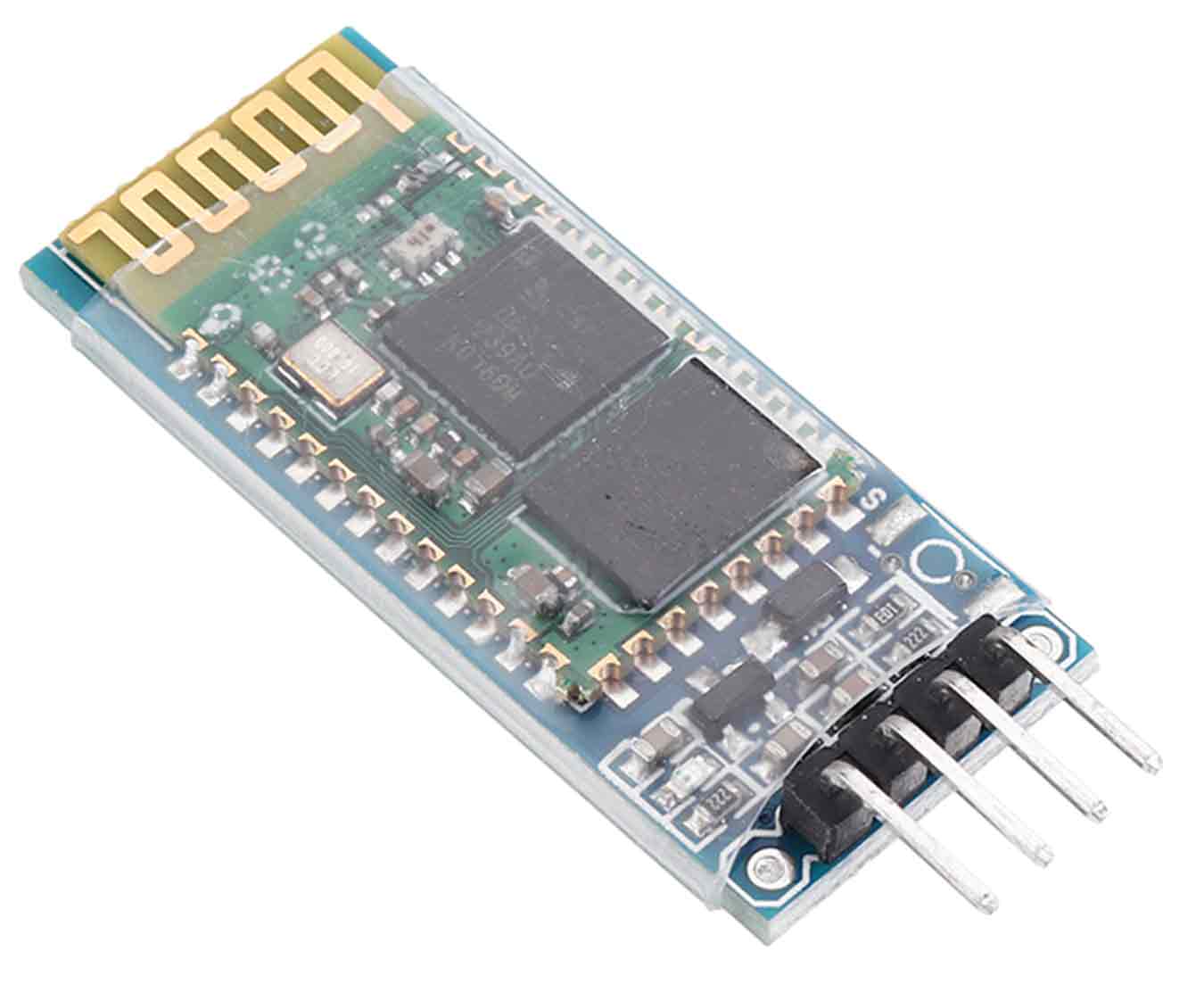
ZS-040 Datasheet Link
2. Plan
- Through the workshop, I learned that I can communicate through Bluetooth with Android phone application.
- So I decided to replace the remote control with a cell phone, and this week I will do an experiment as below.
- Communication with cell phones and Arduino using Bluetooth.
- Bluetooth Communication between my two boards.
3. Communication With Cell Phones And Arduino
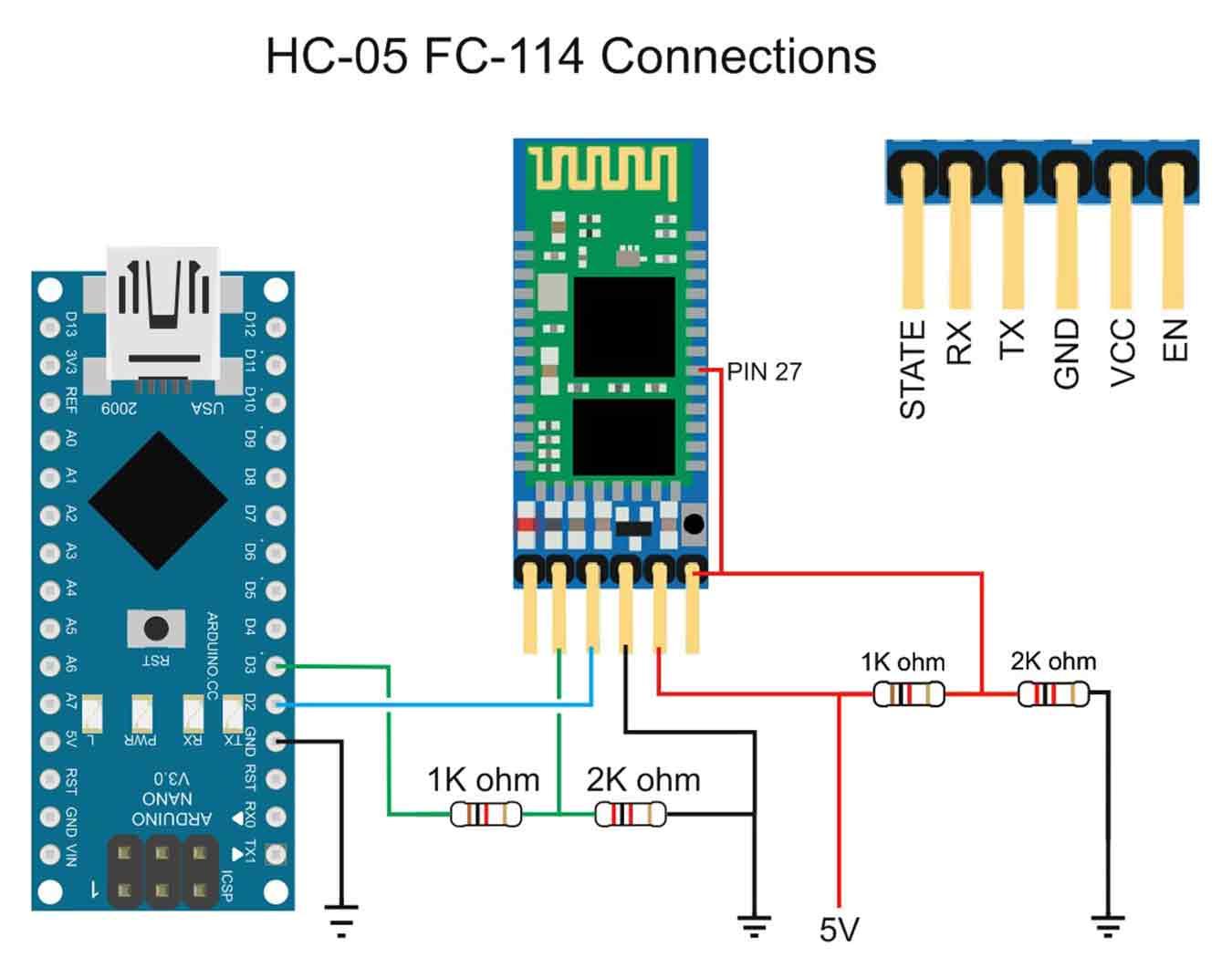
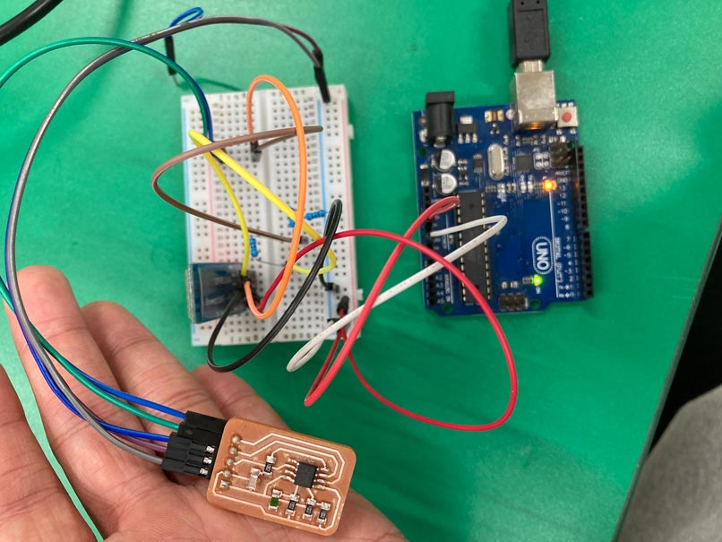
- First, prepare bluetooth dongle, breadboard, Arduino board, jumper wire and three 1K register.
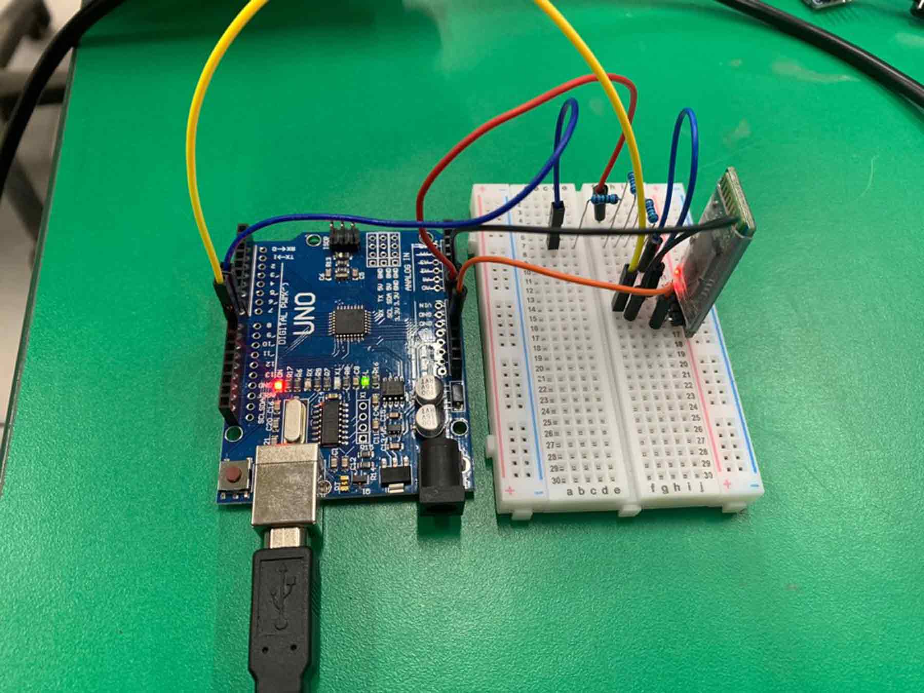
- And connect the supplies by referring to the picture below.
- Ta-da
- Insert the Arduino code into the board, which is designed for Bluetooth communication.
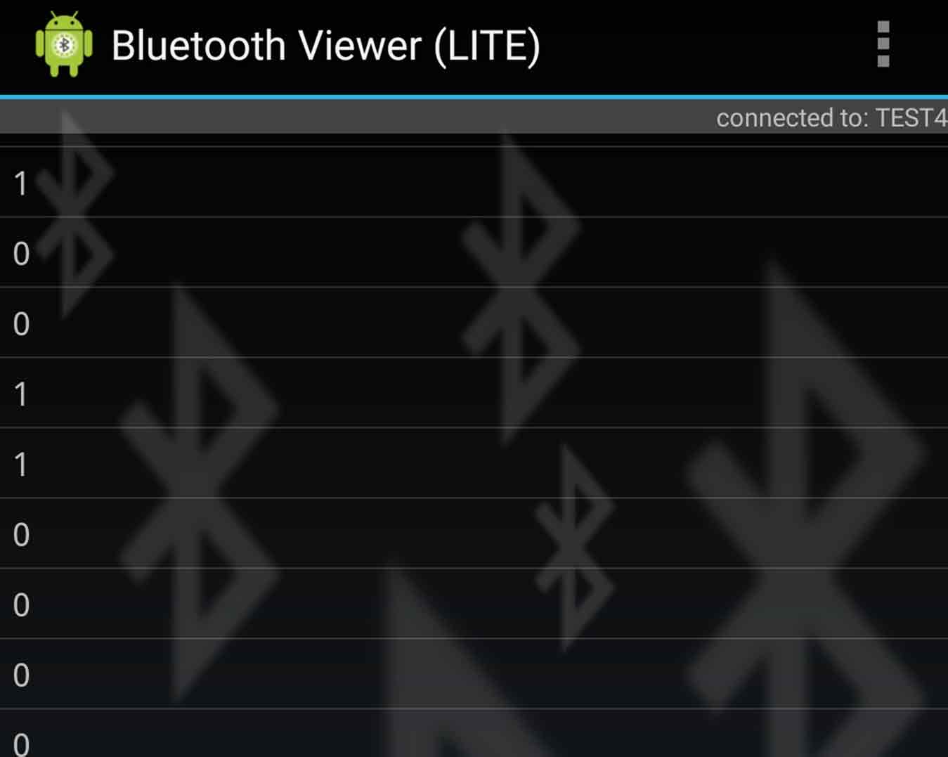
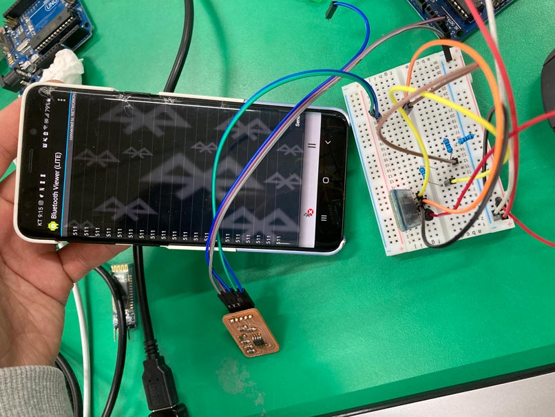
- Then downloads and run the "Bluetooth Viewer" from Android phone.
- Connect Arduino and cell phone by Bluetooth.(The password for Bluetooth Dongle was 1234.)
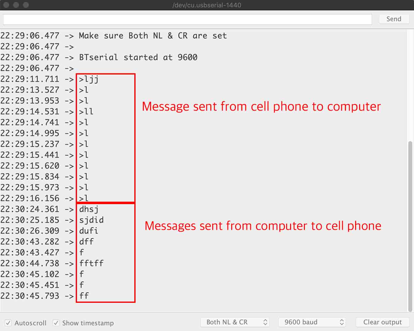
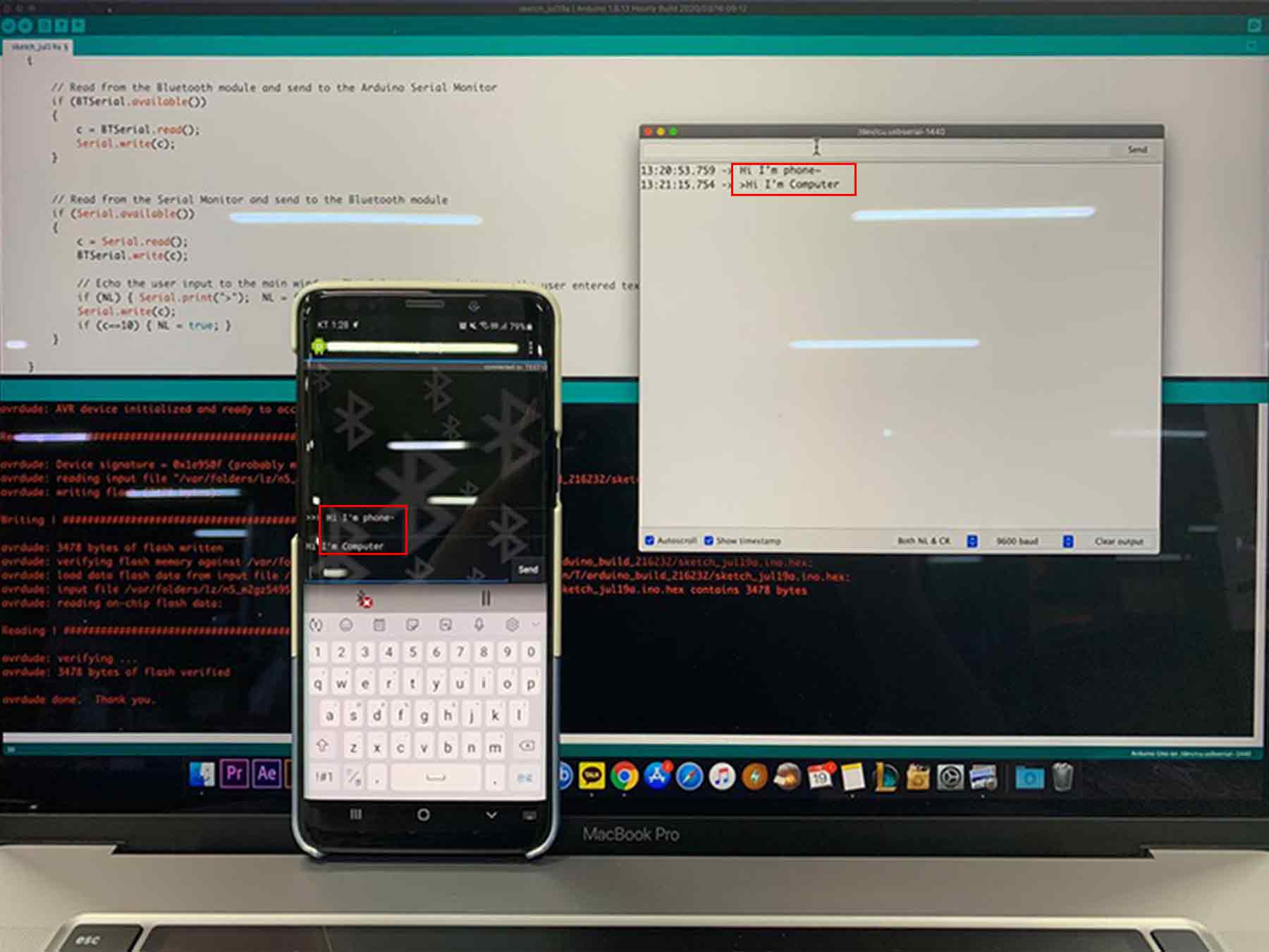
- Communicate successfully.
- Warning
- Bluetooth Dongle should not exceed 3.3v, so the 1k register should be well connected as shown above.
- Trial and Error
- The rx of the Bluetooth Dongle must be connected to the tx of the Arduino Board, and the rx of the Arduino Board must be connected to the tx of the Bluetooth Dongle.If you don't pay attention, the serial monitor won't react and if you don't, the dongle may break. (I spent 10 minutes wondering what the problem was because of this.)
- In the final project
- This time, I just communicated on a serial monitor, but in the final project, I decided to use "App Inventer" to create an application and connect the temperature sensor board to Bluetooth to check the figures.
There was confusion to confirm the additional messages received only with this(>). So I fixed it with "phone ->"
// Basic bluetooth test sketch. HC-0x_FC-114_01_9600
//  Uses hardware serial to talk to the host computer and software serial for communication with the bluetooth module
//
//  Pins
//  BT VCC to Arduino 5V out.
//  BT GND to GND
//  Arduino D3 to BT RX through a voltage divider
//  Arduino D2 BT TX (no need voltage divider)
//
//  When a command is entered in the serial monitor on the computer
//  the Arduino will relay it to the bluetooth module and display the result.
//
// The HC-0x FC-114 modules require CR and NL

#include <SoftwareSerial.h>
   SoftwareSerial BTSerial(9, 8); // RX | TX


   char c=' ';
   boolean NL = true;

   void setup()
   {
       Serial.begin(9600);
       Serial.println("Sketch HC-0x_FC-114_01_9600");
       Serial.println("Arduino with HC-0x FC-114 is ready");
       Serial.println("Make sure Both NL & CR are set");
       Serial.println("");

       // FC-114 default baud rate is 9600
       BTSerial.begin(9600);
       Serial.println("BTserial started at 9600");
       Serial.println("");

   }

   void loop()
   {

       // Read from the Bluetooth module and send to the Arduino Serial Monitor
       if (BTSerial.available())
       {
           c = BTSerial.read();
           Serial.write(c);
       }


       // Read from the Serial Monitor and send to the Bluetooth module
       if (Serial.available())
       {
           c = Serial.read();
           BTSerial.write(c);

           // Echo the user input to the main window. The "phone ->" character indicates the user entered text.
           if (NL) { Serial.print("phone ->");  NL = false; }
           Serial.write(c);
           if (c==10) { NL = true; }
       }

   }
}
4. Connection Between My Two Boards
- I was planning to communicate through Bluetooth using my temperature board and button board.
- I got an offer from Craig. Connect the node-red of the computer as a bridge between the two boards to communicate.
- First, I had to send serial to a computer connected to Bluetooth when I pressed the button on the buttonboard.
↓The first Arduino code
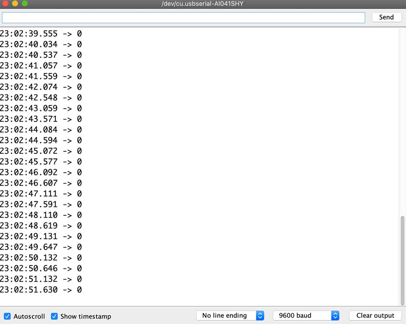
- But nothing appeared on the serial monitor.
- I found out that there was a problem with the code, and that my serial was constantly.
- I learned about "\n," which means a line break, and realized that writing a code without this code would be like continuing to type without pressing enter.
↓Corrected code
↓Left-Arduino Serial Monitor / Right - Android Phone (Bluetooth Viewer)
- I corrected the code and tried again. The result is a success! I checked first with a more comfortable cell phone before checking on the computer.
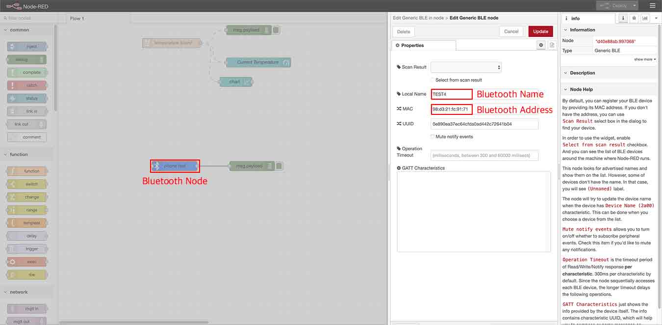
- So I downloaded the Bluetooth serial node(From the menu icon in the upper right > manage pallette > pallette > install) and entered the name and address of the Bluetooth module. It was not connected to several attempts. I googled, and I couldn't find a solution.
- In the result, I gave up this method and decided to do Bluetooth communication with only two Bluetooth modules.
- All Bluetooth models at Fab Lab in Seoul are HC-06. There is no button, there are just 4 pins.
- In order to do so, I knew that there should be a master module and a slave module.
- The HC-06 model was basically set up as a slave and had to make one of the two master module.
- First, put the code below on the Arduino board connected to Bluetooth.
↓example code Link
#include "SoftwareSerial.h"
SoftwareSerial bluetooth(TX, RX);

void setup(){
 Serial.begin(9600);
 bluetooth.begin(9600);
}

void loop(){
 if (bluetooth.available()) {
   Serial.write(bluetooth.read());
 }
 if (Serial.available()) {
   bluetooth.write(Serial.read());
 }
}
- And you can use "AT" on the serial monitor to communicate with the Bluetooth board to view or change the setting values of the dongle.
↓Bluetooth AT Commend List Link
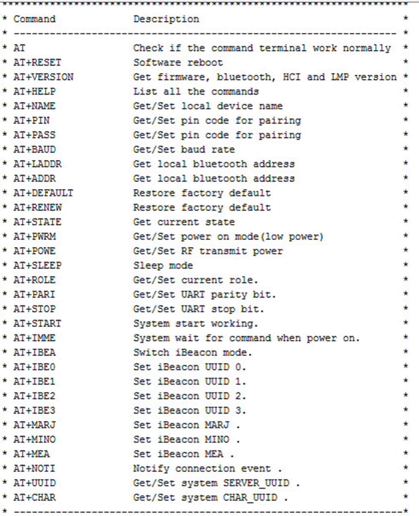
- The command to make the dongle a slave is "AT+ROLE=0" and the command to make it a master is "AT+ROLE=0". The first is the result of the command "AT", the second is the command "AT+VERSION", the third is the command "AT+NAME FAB", and the fourth is the command "AT+ROLE=1".
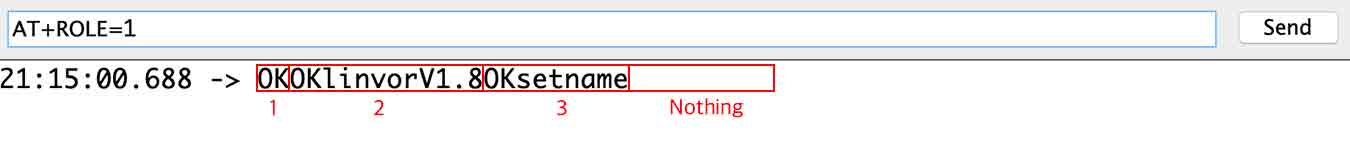
- The command "AT+ROLE=1" did not work even if you keep typing.
- I kept googling, and I found out that HC-06 is a model that cannot be changed to a master.
Hopeless....
- So I've searched with the keyword "blutooth slave to slave communication"... The result is...
↓Slave to Slave Comminication with HC-06 devices? Link
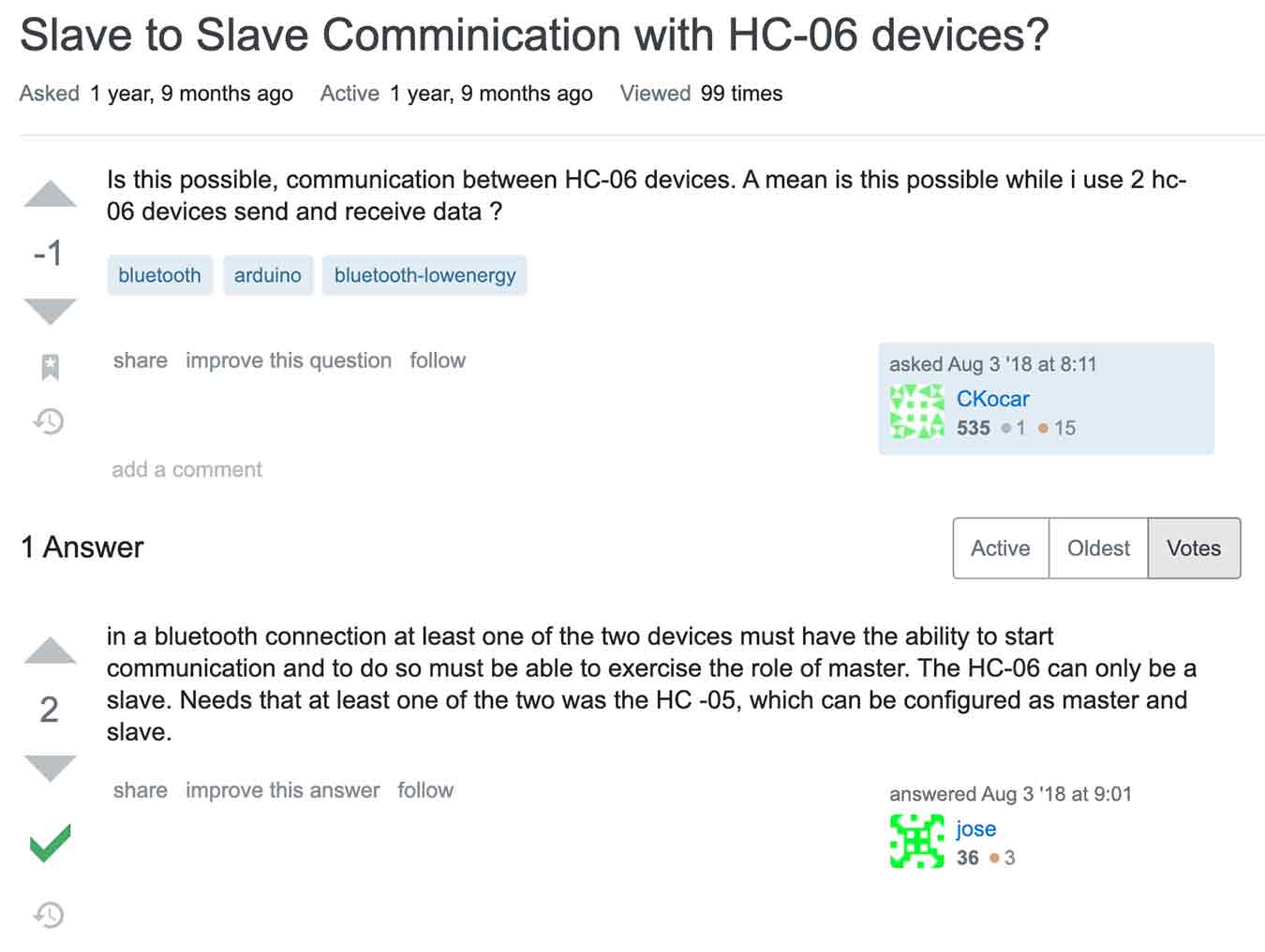
Again Hopeless....
Meanwhile, a blog said, "Slave and master settings are possible on version 1.7 or higher(My board version is 1.8!!! Oh yeah!!)"
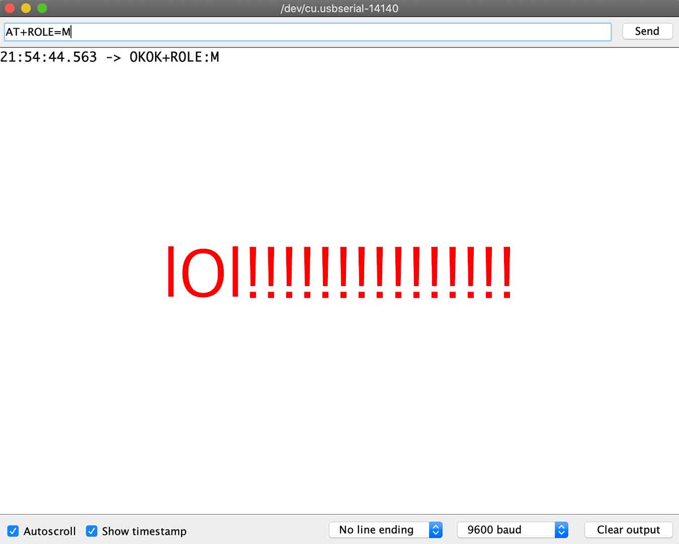
The reason why I didn't work was that the commands were slightly different depending on the version. In HC-06 - 1.7 and later, master changes are possible using the command (AT+ROLE=M) and earlier versions are not possible. In addition, the command (AT+ROLE=1) is used in the HC-05 module to switch to master mode.
But then this happened.
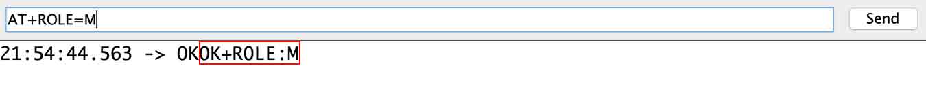
- It's a success! Yes~~~~~~~ Now we can move on to the next one!!!!!!
↓This is the most meaningful hero shot for me this week.
I was too exhausted at this time. So we decided to communicate simply by using two Bluetooth boards. At that time I found this video, and I decided to refer to it and try to communicate.
Button>Aduino Board>Bluetooth Master>Bluetooth Slave>Aduino Board>LED
chose to deliver such information.
↓Master & Button, Slave & LED
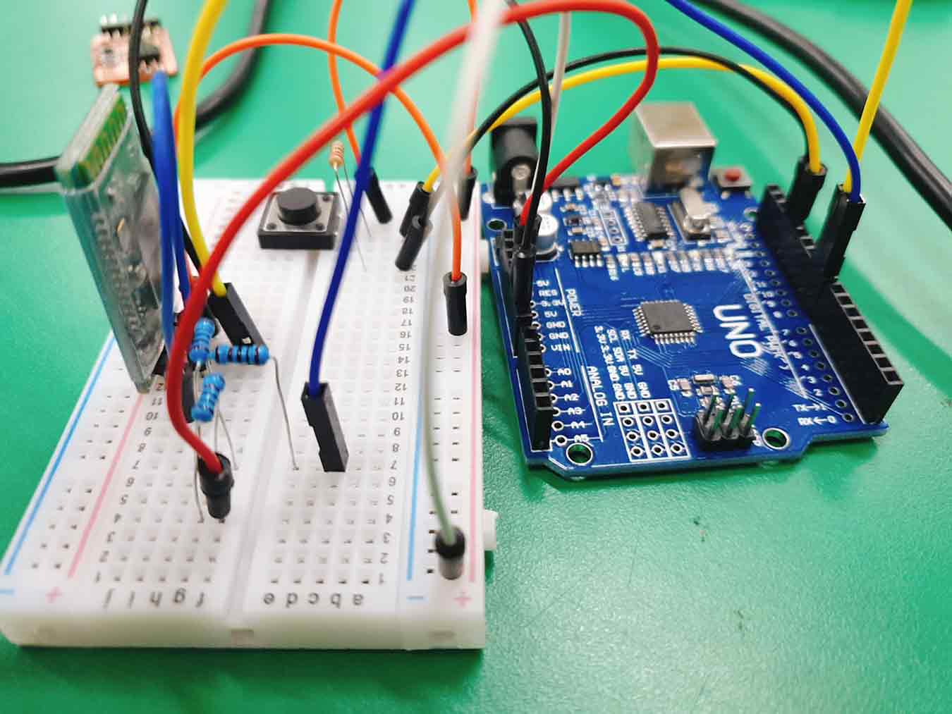
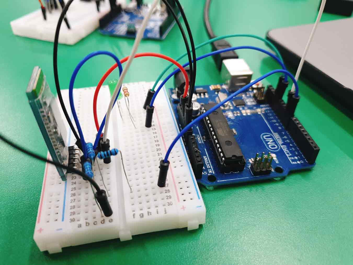
First, I connected the Bluetooth board to the Arduino board and additionally the button and LED to pin 13 of each Arduino board.
Master & Button Code
#include <SoftwareSerial.h>
SoftwareSerial BTSerial(1, 2);   //bluetooth module Tx:Digital 2 Rx:Digital 3

int btn = 4;
void setup() {
 pinMode(8, OUTPUT);
 digitalWrite(8,HIGH);
 Serial.begin(9600);
 BTSerial.begin(9600);
 pinMode(btn, INPUT);
}
void loop() {
 char data;
 int value;
 value = digitalRead(btn);
 if(value == 1){
   data = '1';
 }else{
   data = '0';
 }
 BTSerial.write(data);
 Serial.println(data);
}
This is Master & Button Code. It is a code that sends a signal of 1 when a button is pressed with slave Bluetooth and a signal of 0 if it is not pressed.
Slave & LED Code
#include <SoftwareSerial.h> //블루투스 시리얼 통신 라이브러리 추가
SoftwareSerial BTSerial(9, 8); //블루투스 객체 선언 및 초기화 (Tx, Rx)

//LED 핀 설정
int LED1 = 13;

void setup() {
 BTSerial.begin(9600); //블루투스 통신 시작 (통신속도)
 pinMode(LED1, OUTPUT); //LED 출력으로 핀모드 설정
}

void loop() {
 if(BTSerial.available()){
   //블루투스 통신이 사용되었다면?
   char bt;
   bt = BTSerial.read(); //블루투스 통신 전달 값 입력
   if(bt == '1') { // 'bt' 변수에 전달된 값이 '1'이라면?
     digitalWrite(LED1, HIGH); //LED 켜기 'on'
     delay(1000);
     digitalWrite(LED1, LOW);
     delay(500);
     digitalWrite(LED1, HIGH);
     delay(1000);
     digitalWrite(LED1, LOW);
     delay(500);
     digitalWrite(LED1, HIGH);
     delay(1000);
     digitalWrite(LED1, LOW);
     delay(500);
   }
   else if(bt == '0'){ // 'bt' 변수에 전달된 값이 '0'이라면?
     digitalWrite(LED1, LOW); //LED 끄기 'off'
   }
 }
}
Slave & LED Code. The original code is code that the LED turns on when it receives a signal of 1 and turns off when it receives a signal of 0, but the LED has been modified to flash when it receives an additional signal of 1.
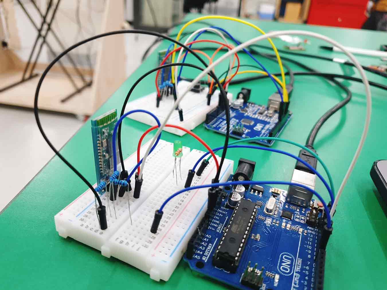
Completed Bluetooth communication between the two Arduino boards
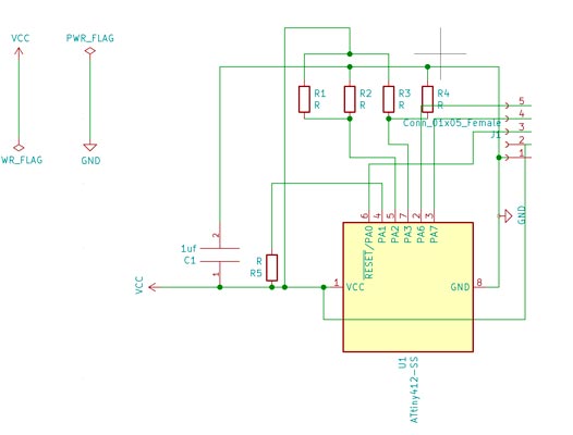
5. Communication Between Cell Phones and Temperture Board
I made a new board to allow tx rx communication by modifying the temperature board I made in nine weeks.
This time, we used ATtiny412, which is easy to put in code.
↓This is the changed PCB drawing.
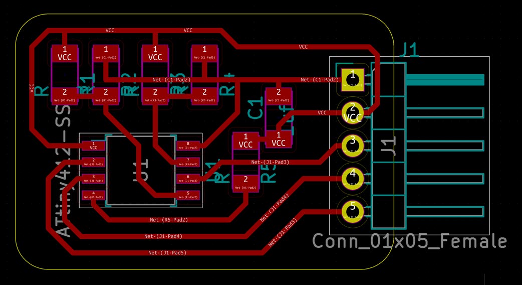
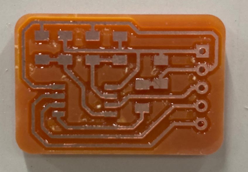
↓Milling and soldering....
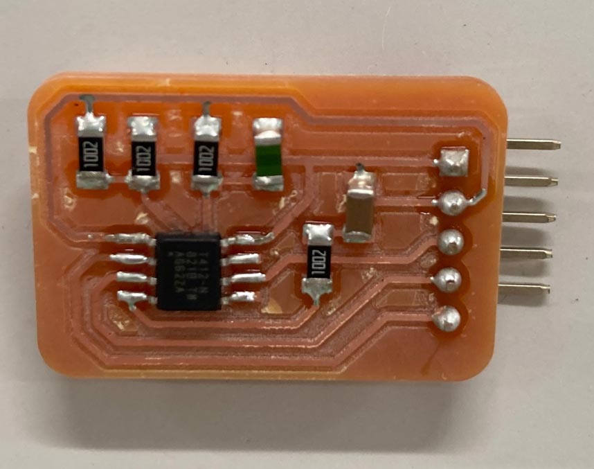
I put the code in using jtag. Code removed software serials because unlike Arduino, MCU used ATtiny412.
↓Milling and soldering....
  const int tpin=3;
  //SoftwareSerial mySerial(rx,tx);
  void setup() {
      Serial.begin(9600);
      Serial.println(0000);
  }

  void loop() {
      int t;
      t=analogRead(tpin);
      float tc=calcT(t);
      Serial.println(t);
      delay(100);

  }

  float calcT(int data) {
      float B=3750;
      float T0=298.15;
      float R0=10000.0;
      float R1=11200.0;

      float rr1,t;
      rr1= R1 * data / (1024.0 - data);
      t = 1 / (log(rr1 / R0) / B + (1 / T0));
      return (float)(t - 273.15);
  }
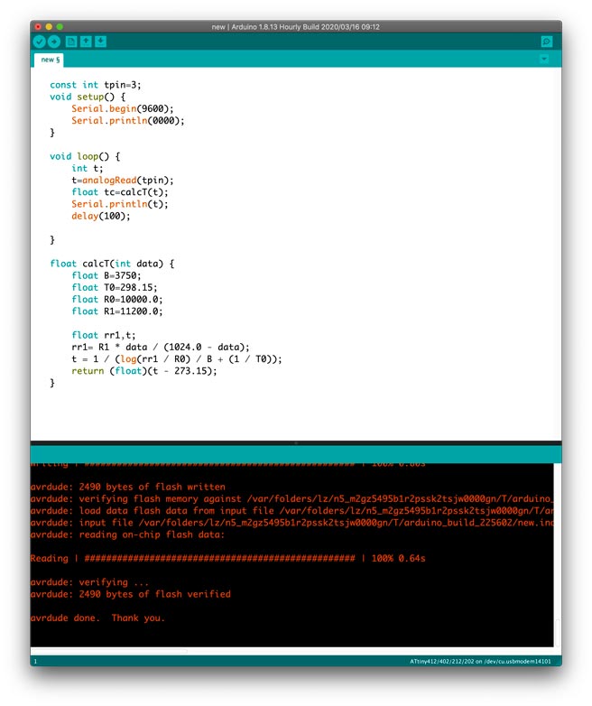
I successfully put the code on the board.
Can click on the link here(WEEK11) to insert the code using ATtiny412 and jtag.
Connected to the board with Bluetooth. Arduino was only allowed to power up.
Success!
Reference
- Bluetooth example code : Link
- ZS-040 Picture : Link
- HC-05 FC-14 Connections Picture and Aruino Code : Link
- Arduino Inter-Aduino Communication Using Bluetooth : Link
File
Node-Red
- Bluetooth Node-Red.json File here
Arduino
- Communication_with_phone_and_arduino.ino File here
- Bluetooth_button_code.ino File here
- Bluetooth_example_code.ino File here
- master_button.ino File here
- slave_LED.ino File here
- new_temperture_board_code_week14_1128.ino File here
KiCad - Temperature Board
- WEEK9_Analog_Temperature_Senser_Board_0328-F_Cu.gbr File here
- WEEK9_Analog_Temperature_Senser_Board_0328-Edge_Cuts.gbr File here
- WEEK14_Networking_Analog_Temperature_Senser_Board_1128-Edge_Cuts.gbr File here
- WEEK14_Networking_Analog_Temperature_Senser_Board_1128-F_Cu.gbr File here
- WEEK14_Networking_Analog_Temperature_Senser_Board_1128.drl File here