4. Electronics production
Assignment
Group assignment
- Characterize the design rules for your PCB production process: document feeds, speeds, plunge rate, depth of cut (traces and outline) and tooling.
- Document your work (in a group or individually)
Group Project here
Individual Assignment
- Make an in-circuit programmer by milling and stuffing the PCB, test it, then optionally try other PCB processes
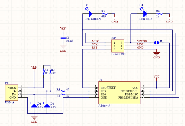
[ISP]
Vary Hard Week
I followed Brian(ATtiny45).
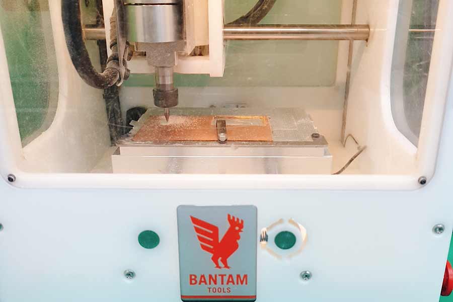
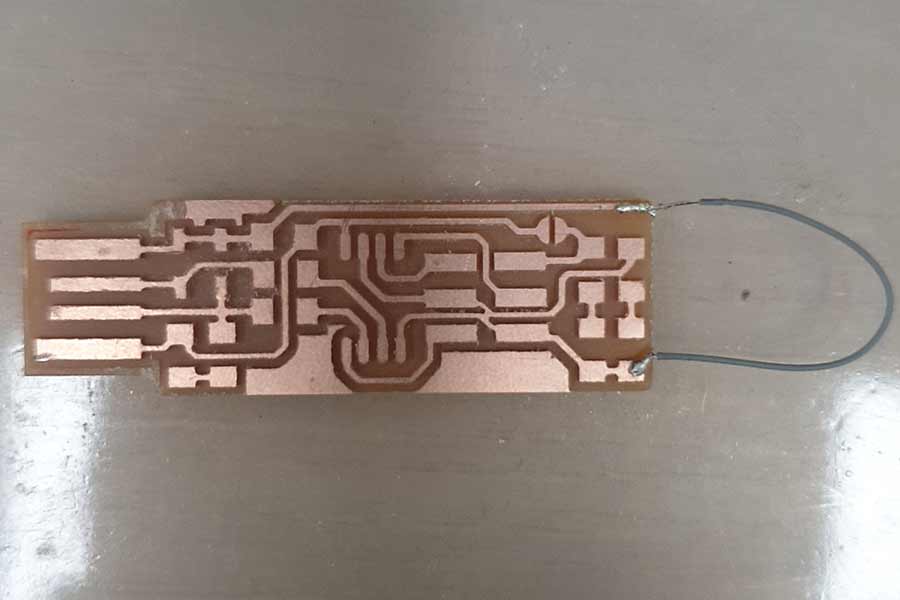
I downloaded the design from the web page above and used to milling for 'BANTAM'. I followed the process documented on the group page.
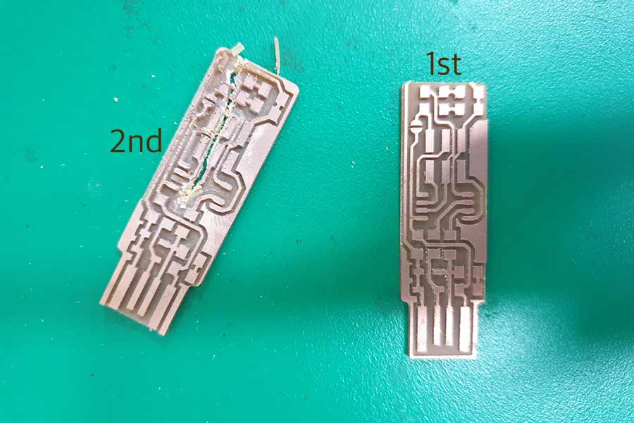
Cut board 1, but the outline was miss-aligned and cut the end off. Cut board 2, but it came off the bed during milling and got cut in half.
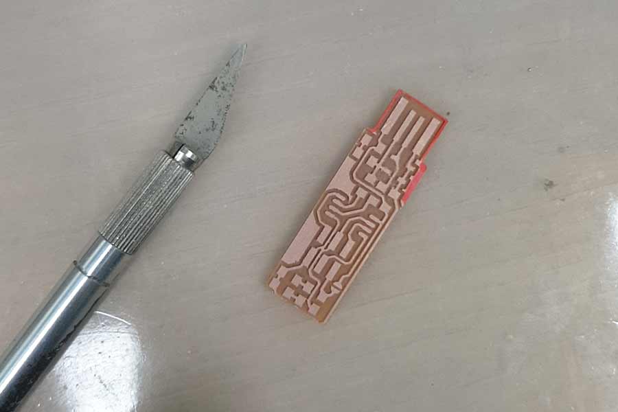
CUT! RED AREA!
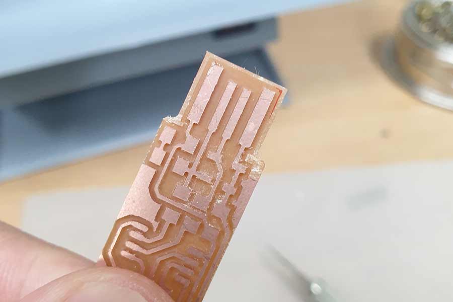
Cool!
WIRE THE BACK!
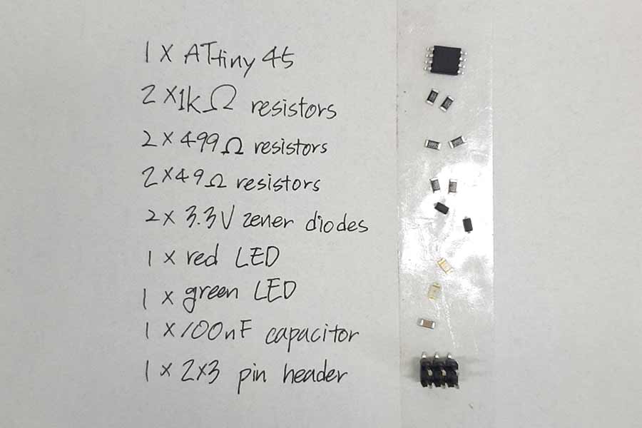
Taped all the The FabTiny Components individually next to their names written on a piece of paper. this helped to keep save time.
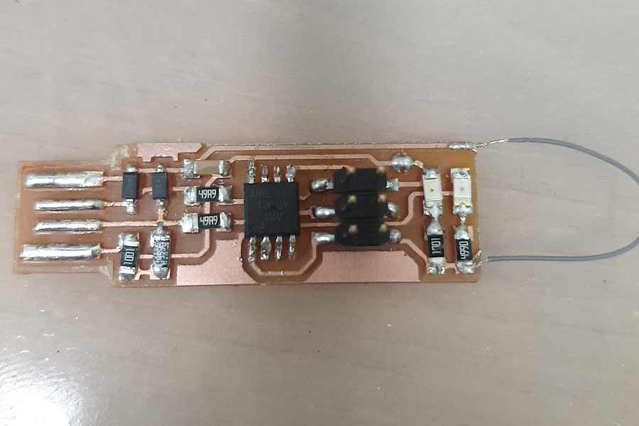
All soldering. I was happy at this time, but this is when hell started.(many failures)
Repaired board 1 as documented. (Jumper, diodes, solder bridges)
The program could not proceed after downloading the software and the program because it was passed without checking the basics.
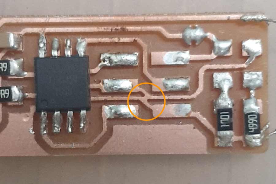
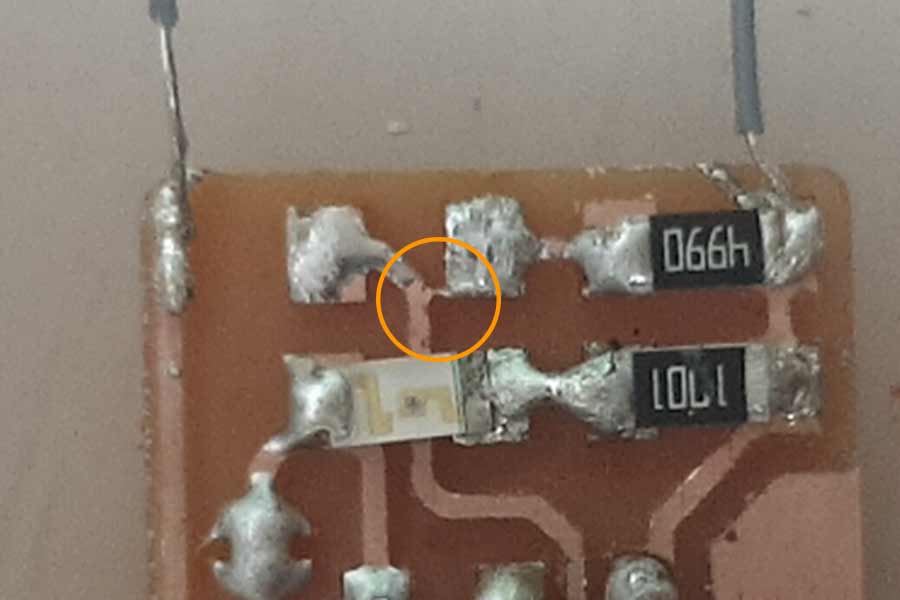
The parts that should not be connected were connected and and the diodes were soldered around the wrong way.
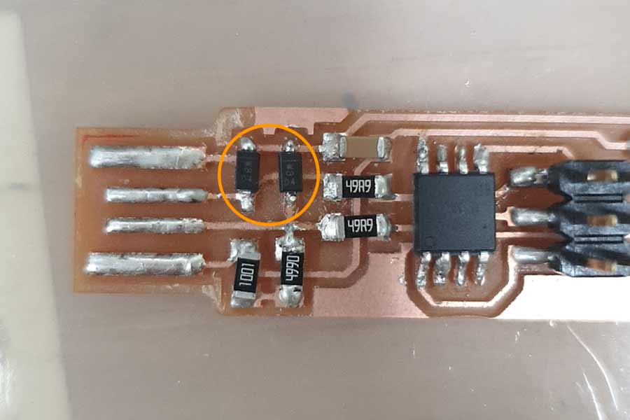
Like this!
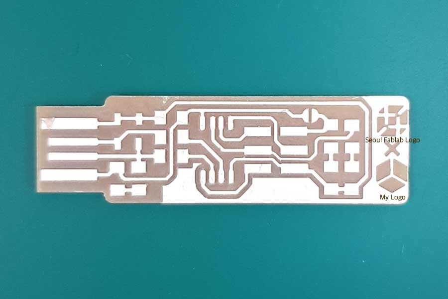
My first board had too many faults. I was so tired of fixing them, and it took so much time. (almost three days) So I decided to make a new board using the things I learned while fixing the first board. In addition, using my icon and the icon of Seoul Innovation Lab.
I vowed to make this board a success without fail.
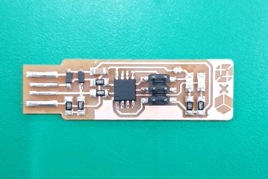
Carefully Soldering!
While soldering, I checked whether the components were soldering well or not, checking whether the current was flowing well with the multimeter, and adjusting the amount so that the component could only attach to the board.

This time, I checked these pictures carefully.
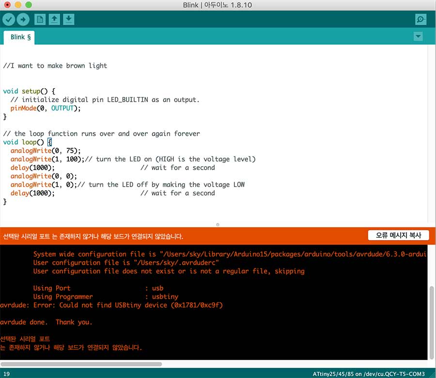
Accidentally disabled the reset fuse too soon preventing it from being programed
Used the reflow station to replace the attiny chip but burnt the PCB slightly
(Have some burn marks on board.The code did not go in while coding, so I used the flow station to replace MCU. I worked by setting the temperature to 300 degrees. This temperature was too hot for the circuit board. I realized that lead melts even if I use a flow station at 280 degrees. Next time, I will set the temperature low to prevent the circuit board from burning.)
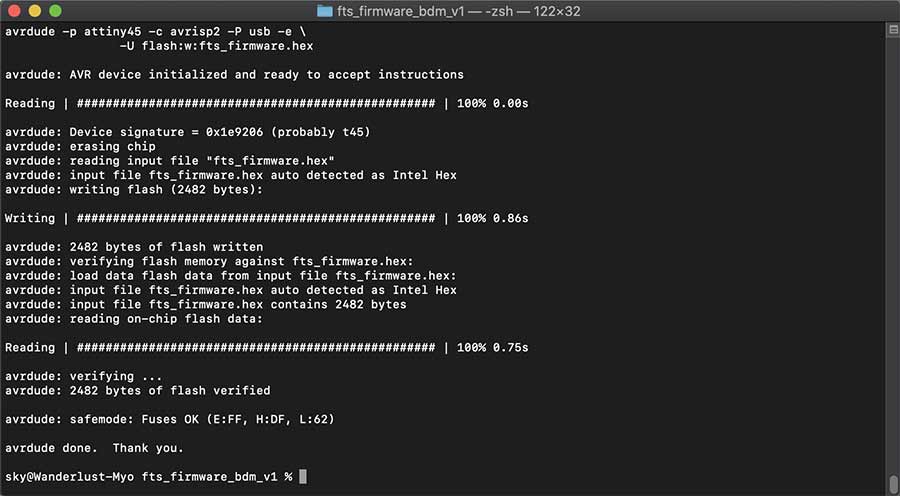
Working ISP uploading code on my board followed this link.
Ran four commands.
make > make flash > make fuses > make rstdisbl
make - This will build the hex file that will get programmed onto the ATtiny45. When the command completes
make flash - This will erase the target chip, and program its flash memory with the contents of the .hex file you built before.
make fuses - This will set up all of the fuses except the one that disables the reset pin. Again, you should see several progress bars from avrdude.
make rstdisbl - This does the same thing as the make fuses command, but this time it's going to include that reset disable bit as well. You should see some progress bars, and with that, avrdude will never be able to talk to this chip again through the ISP header.
Further details can be found in the above link.
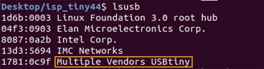
Used linux to; set the fuses, upload the firmware, check it was detected & disable the reset
Board wasn’t detected on OSX.

Soldered on external USB plug to test if contacts were the problem.
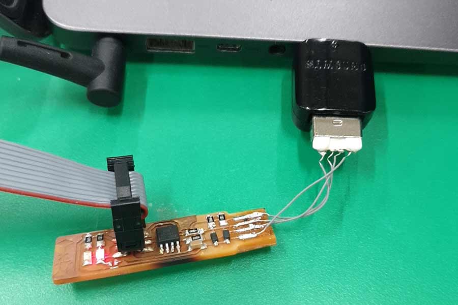
Discovered the issues was v-usb support under OSX
I looked up the problem of Unable to get USBtinyISP to work with Max OSX Catalina through Google, and I was able to find the answer on this link.

I programmed my hello echo board during electronics design week. But OSX didn't recognize the board, and couldn't put the Arduino code.
Later, I uploaded the Code to another pcb board using my isp through another Linux computer.
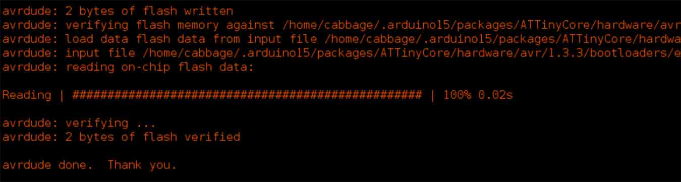
Success!