Electronics Production
Hay Guys! We gotta
participate in a group projectbefore yougo anywhere.
Electronics Production
Result Value
| Type of endmill | 0.4mm | 0.8mm |
|---|---|---|
| Feed Rate (mm/min) | 180.00 | 360.00 |
| Plunge Rate (mm/min) | 30.00 | 50.00 |
| Spindle Speed (rpm) | 12000 | 12000 |
| Stepover (%) | 15.00 | 15.00 |
| Pass Depth (mm) | 0.05 | 0.15 |
| Clearance (mm) | 0.8 | N/A |
Characterize the design rules for your PCB production process
We chose trace width jpg files in schedule web page.
Design rules
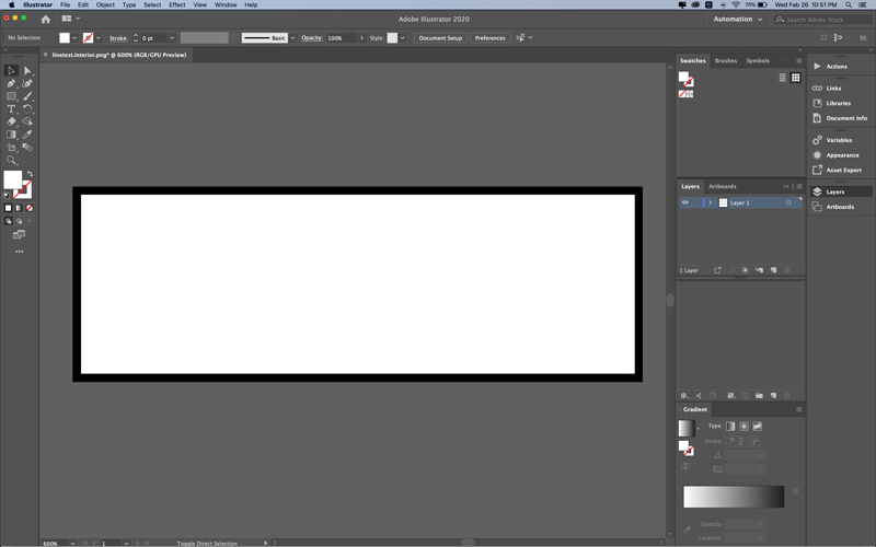
Design illustrator (divide into three steps 1.engraving 2.make hole 3.cutout)
image trace - expand - ungroup - remove the parts to be left - save design files as svg
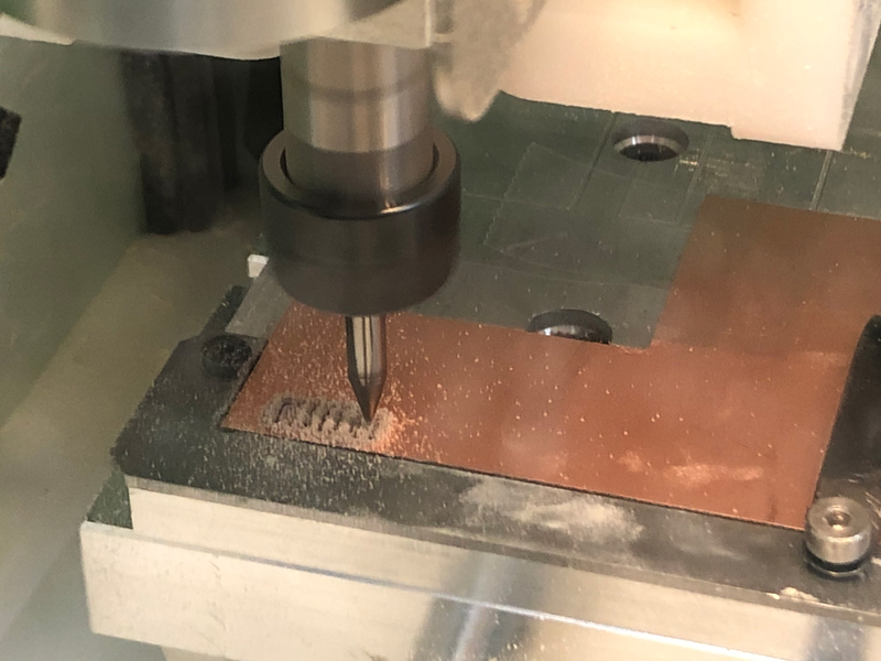
PCB production process
Measure circuit board. (hight, width, thickness)
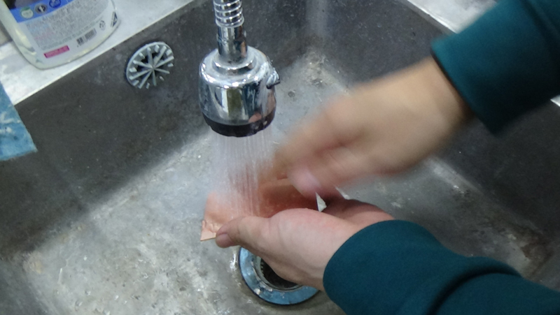
Wash circuit board with water.
Open windows in machine.
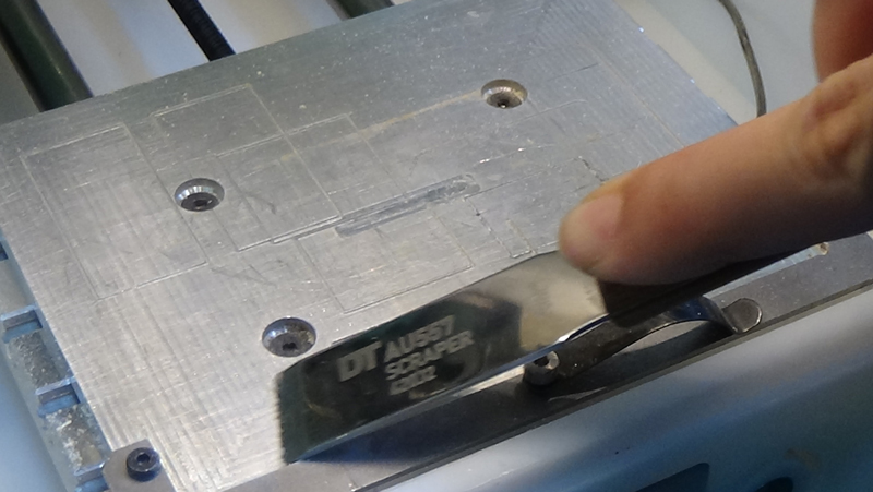
Clean workstation in machine with scraper.
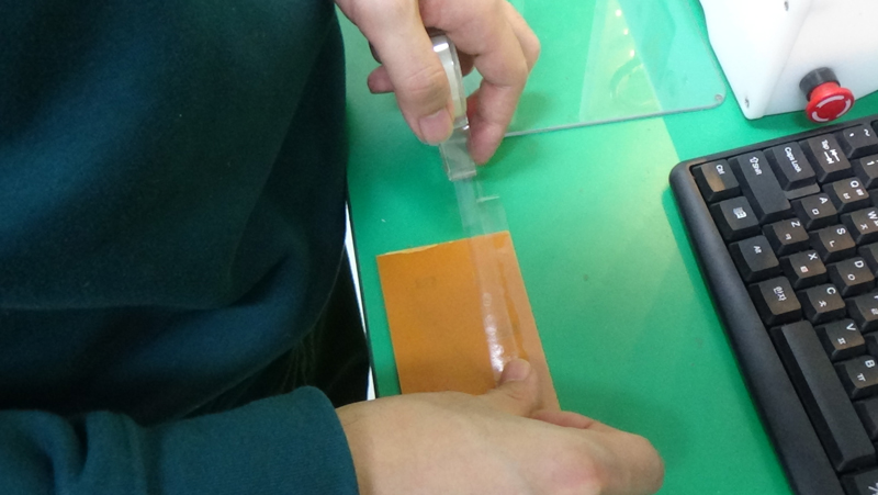
Attach double-side tape to the circuit board back side.
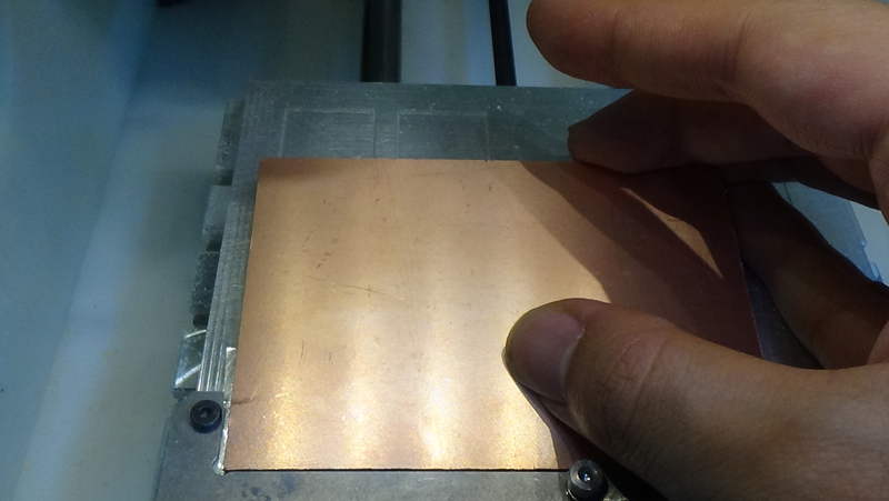
Attach the circuit board to the workstation.
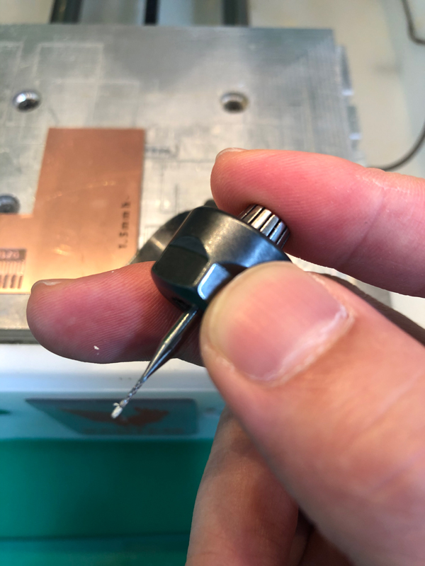
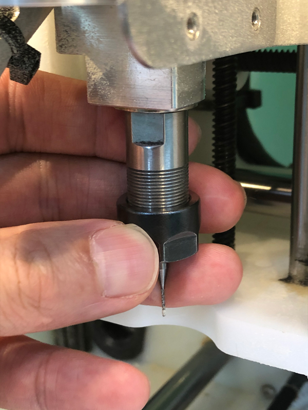
Change to the endmill we use.
Close windows in machine.
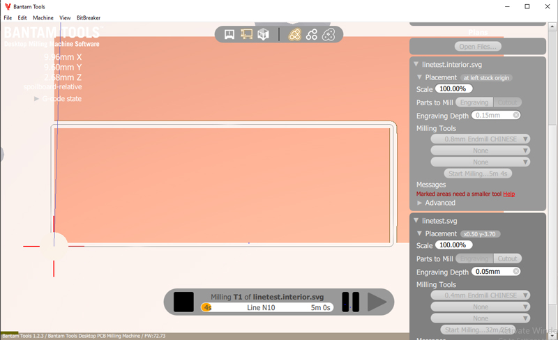
Configure the changed tool in program.
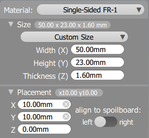
Set board material, size, placement.
Open files to be cut.
Set files placement, scale, parts to mill, engraving depth, milling tools.
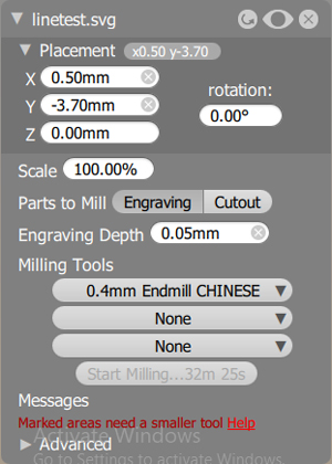
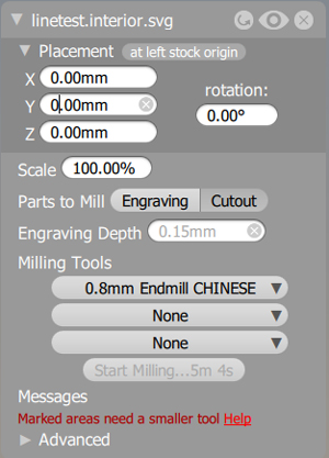
Proceed in two step engraving and cutout.
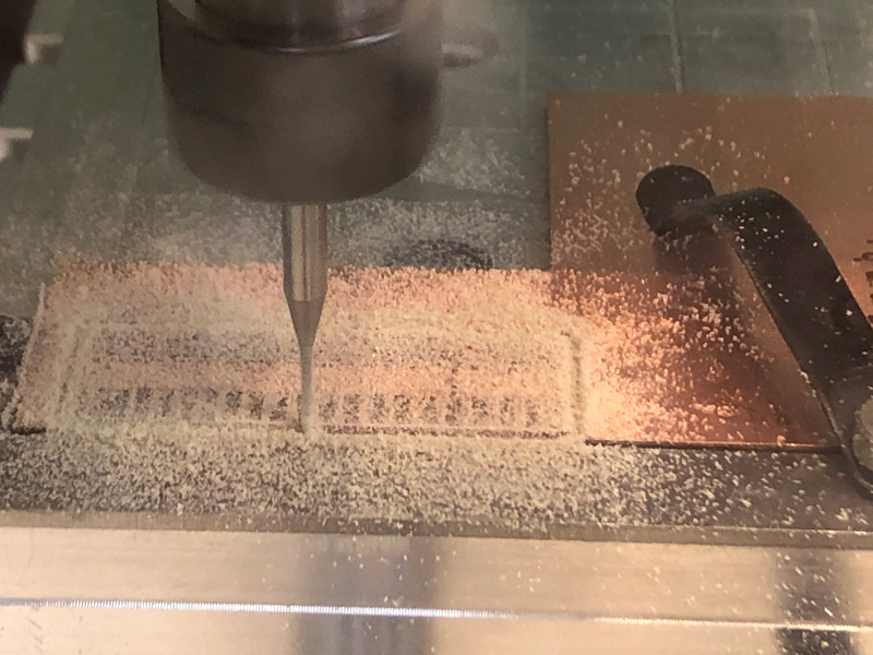
Tools should be changed if different types of work are done. (ex. engraving and cutout)
Clean it with a vacuum at the end of each task.
Wash completed circuit board with water.
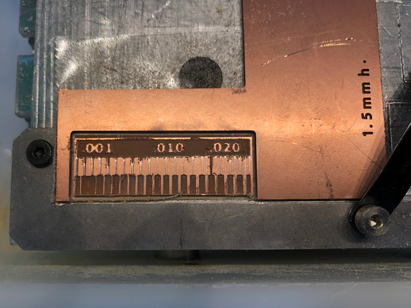
Our result of the group assignment.
What we learned from the group test
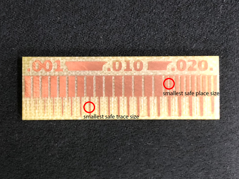
Because our group result was not clearly made, explained other board.
What do you think is the smallest safe trace size to use?
0.008
How much space should you leave between traces?
0.016
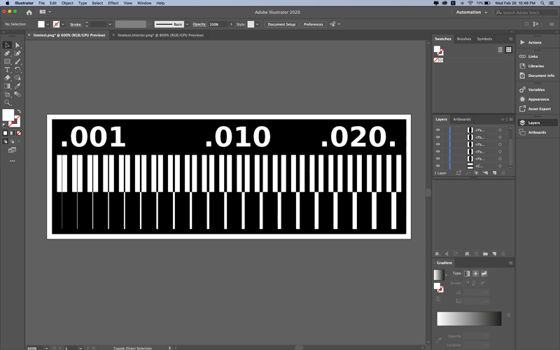
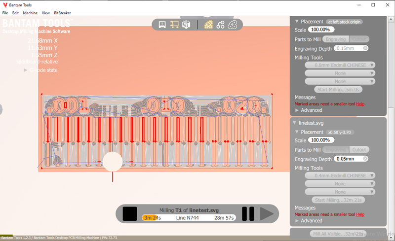
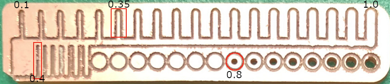
Add test file cut in week 6
We had one more test about the minimum trace size & clearance as well as through hole size. (in mm) We used 0.4mm, 0.8mm of end mill on the Bantam.
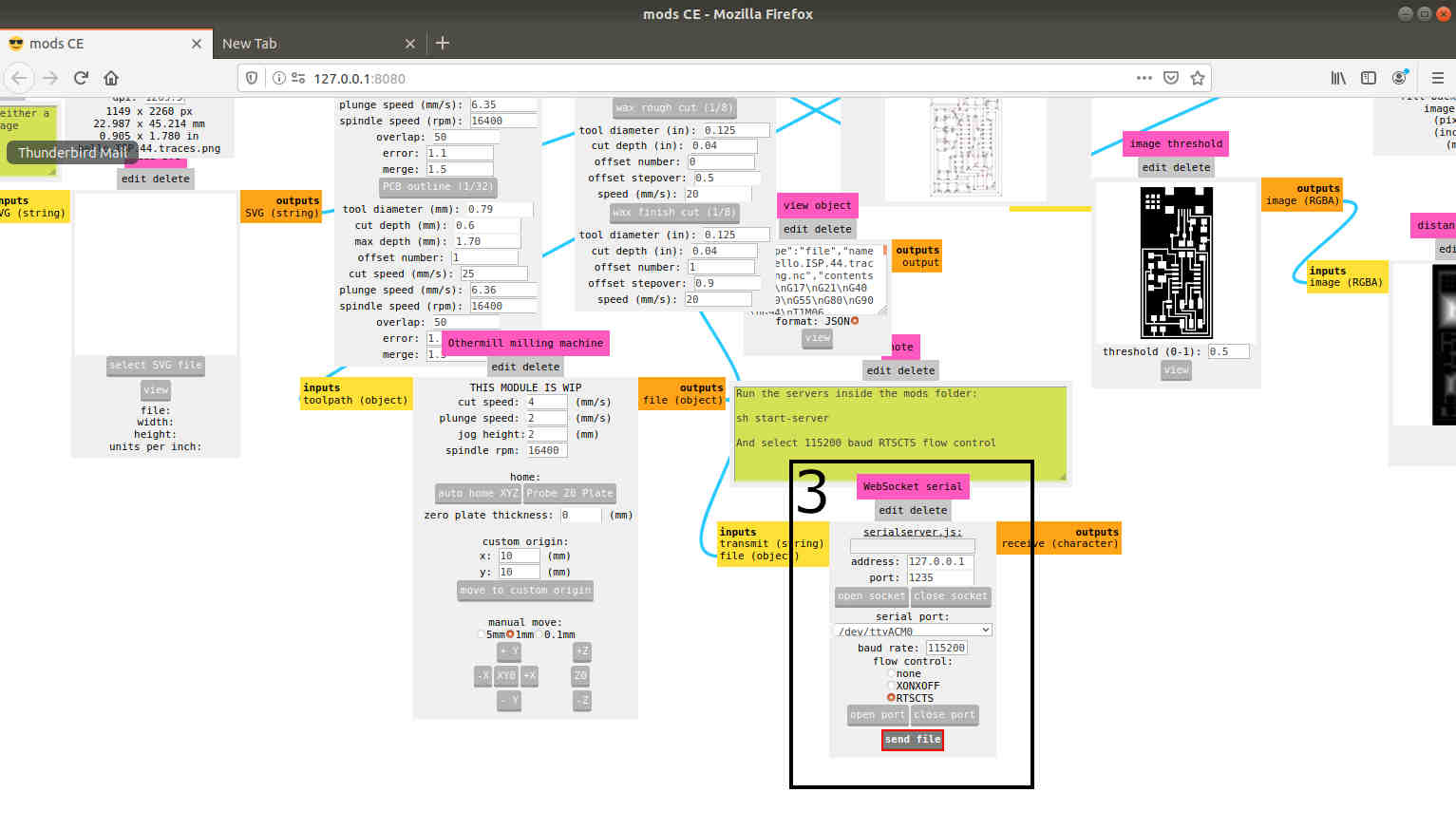
Workflow in MODS
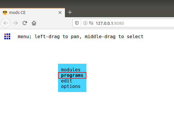
Open MODS, Click mouse right.
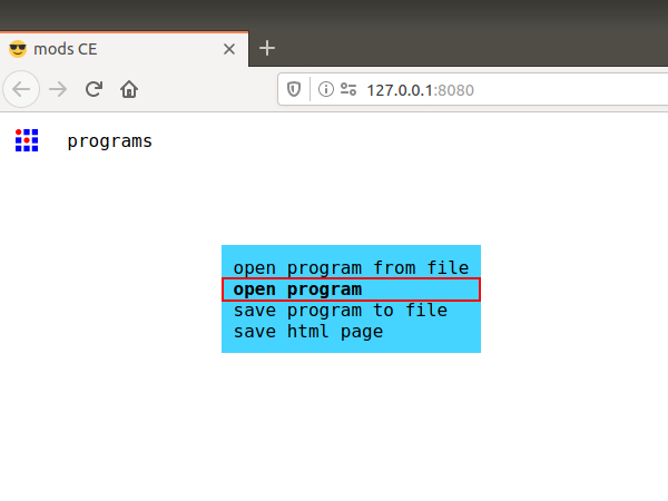
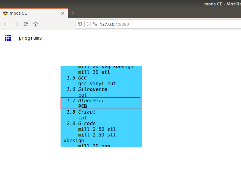
Click program - open program - 1.7 Othermill / PCB
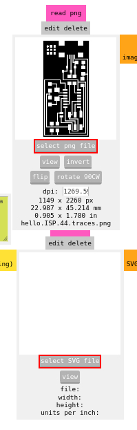
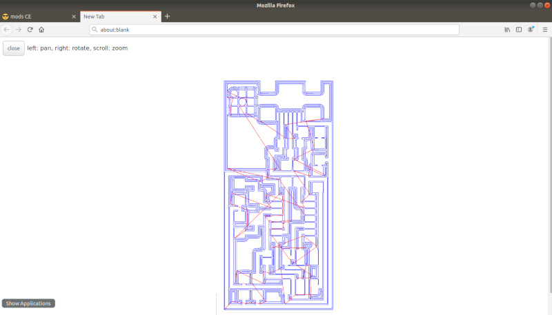
If see this page, Select .png or SVG file. (In MODS, Can use png or svg. And When using svg files, using mods saves more time than using bantam programs. This is because the offset portion can be adjusted in Mods.)
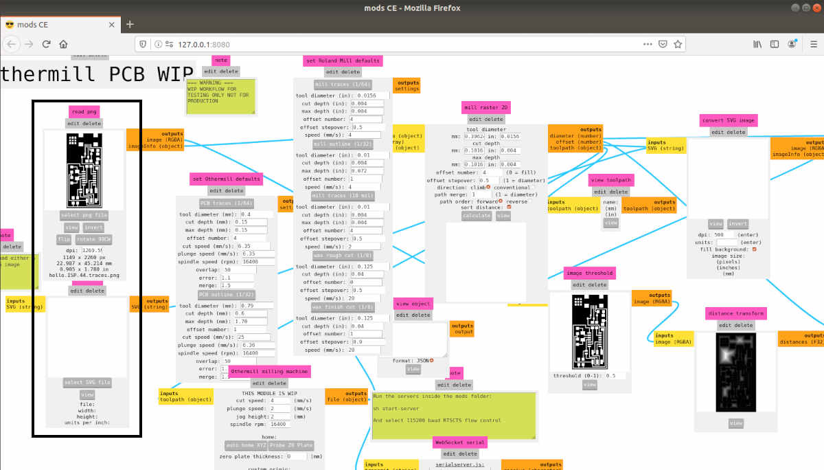
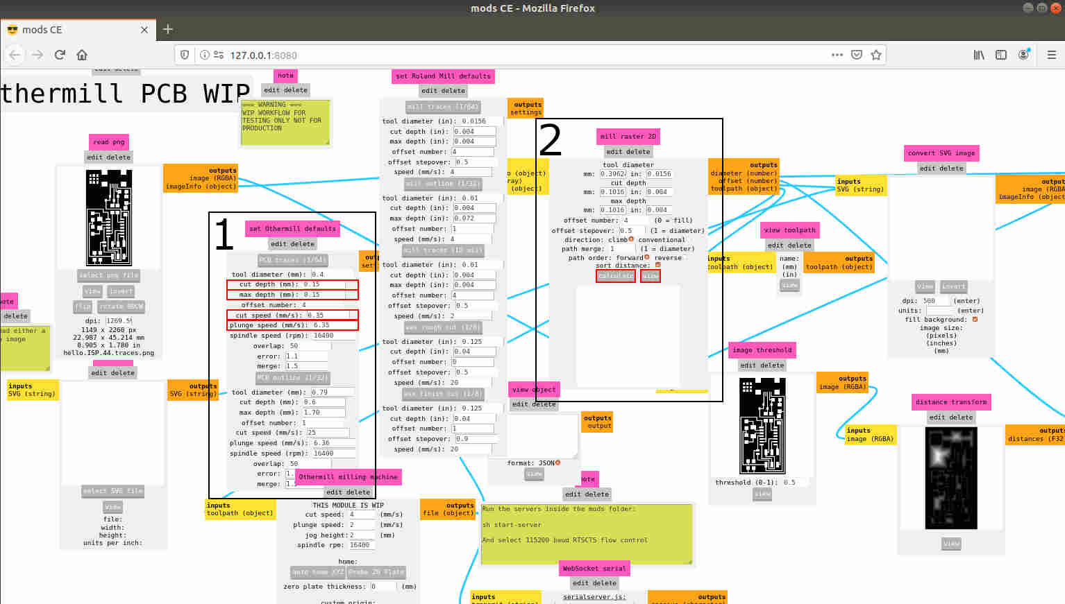
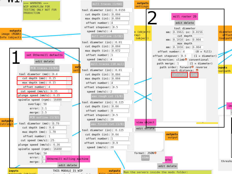
Set ‘cut depth’, ‘max depth’, ‘cut speed’, ‘plunge speed’. (If want to adjust offset, change offset number. 0 = fill)cd
And confirm trace by pressing calculation button. (Press the ‘View’ button to see a larger image.)
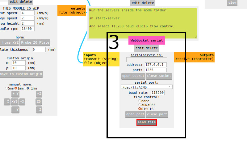
If click ‘send file’, The bantam machine connected to the computer will work.