Computer-Controlled Cutting
Computer Controlled Cutting
Learning Objective: To characterize our laser cutter’s focus, power, speed, rate, kerf, and joint clearance.
trotec speedy 100
This is the trtec speedy 100 laser cutter in the seoul innovation faab lab.
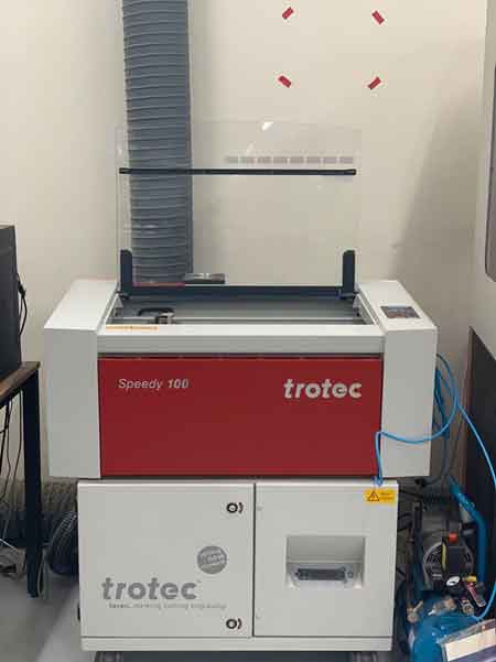
trotec speedy 100 bed size is 600 x 300.
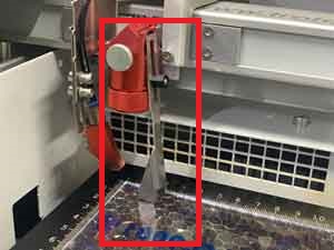
I used 3t acrylic for the kerf test. The trotec z axis can be set using the right iron in the picture. If it touches the base metal, I can say it’s the right height for laser cutting.
set power,speed and work start
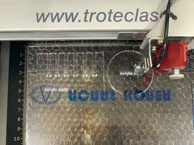
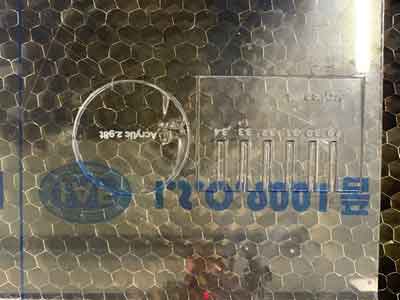
check the acrylic

Acrylic 2.7T(About 3T)
Cut Setting
power : 100, speed : 0.7, PP/Hz : 15000
Engrave Setting
power : 100, speed : 60, PP/Hz : 500
K2 Laser Cutter
At Seoul Innovation Fab Lab, we use K2 Laser Cutter.
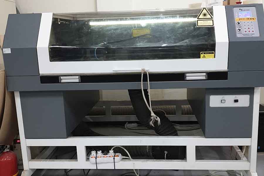 K2 bed size is 1000 x 700.
The K2 laser cutter can be set to power up to 100 speeds up to 200.
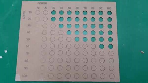
First of all, to find the optimal speed and force, we carried out a test that compares settings that differ by 10 (from 10 to 100). We made a table for easier comparison.
K2 bed size is 1000 x 700.
The K2 laser cutter can be set to power up to 100 speeds up to 200.
First of all, to find the optimal speed and force, we carried out a test that compares settings that differ by 10 (from 10 to 100). We made a table for easier comparison.
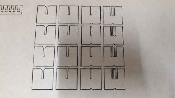
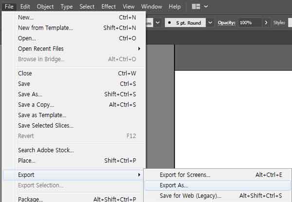
Using Adobe Illustrator, we made a “testing board.”
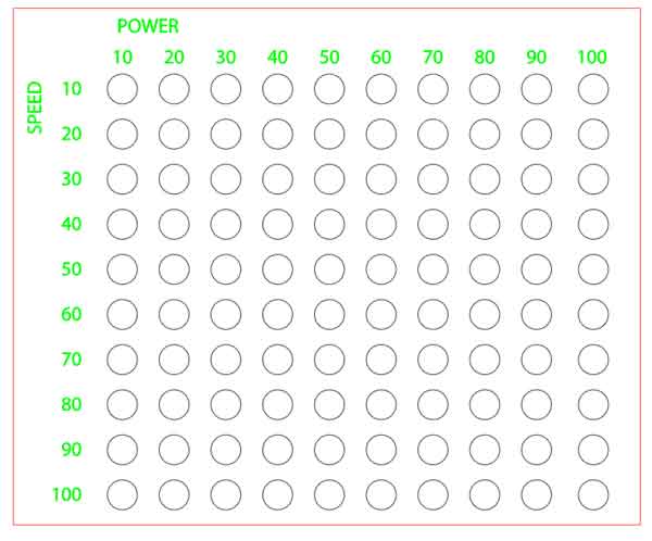
We then converted this testing board file to a DXF file, a file format that is readable by the laser cutter we use in the lab.
After fixating the material (a sheet of cardboard) on the machine bed, we set the focus. The photo below shows the tool for setting the focus when using K2 Laser Cutter.
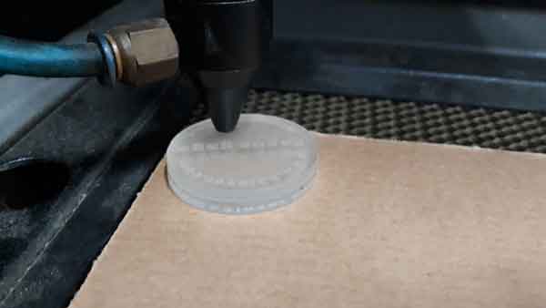
We then cut the “testing board.”
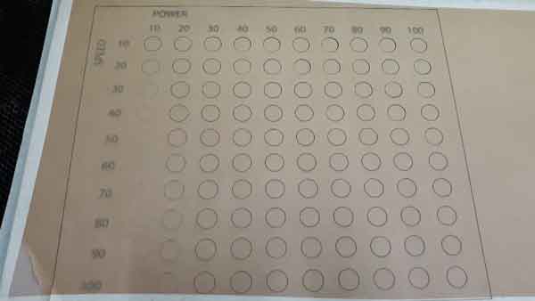
cut speed 60 /power 90
engrave speed100 /power 30
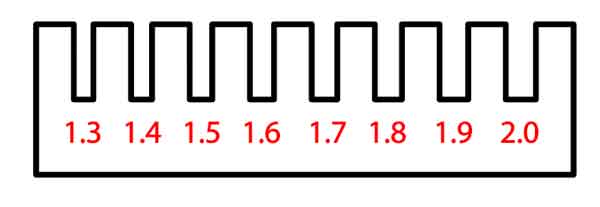
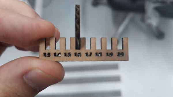
Since we learned the right values for speed and focus of our laser cutter through the test described above, we moved on to the “kerf test.” We used Fusion 360 to design a simple model for this test.
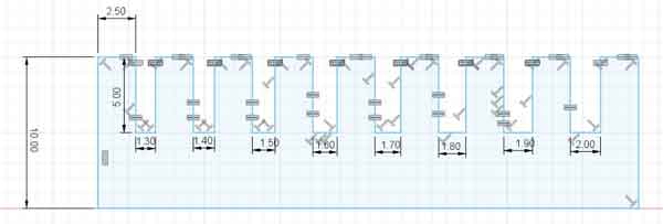
After saving the file on Fusion 360, we opened the Illustrator file to re-save it as a DXF file.
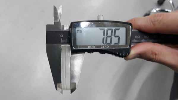
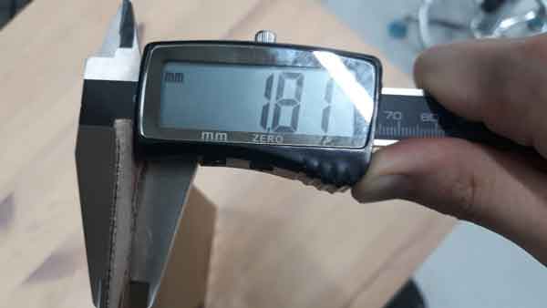
The thickness of the cardboard we used = 1.8mm
As a result of testing several kerfs, we discovered that a 1.6mm gap was the optimal kerf setting. The value of kerf on K2 laser cutter = around 0.1mm.
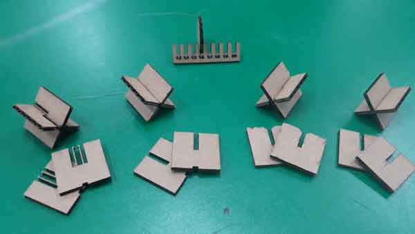
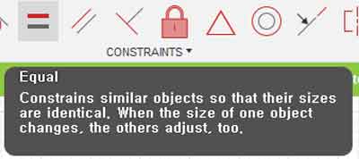
Finally, we designed another simple model on Fusion 360 to carry out a joint test. We made it a parametric design by using the “Equal Function.”
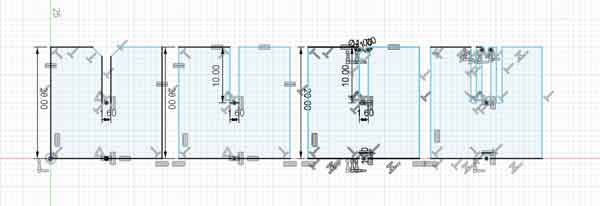
Again, we converted the design made in Fusion 360 to a DXF file on Illustrator.

The photos below show the process and results of the joint cutting.