9. Input Devices
Assignment
Group assignment
- Probe an input device(s)'s analog and digital signals
- Document your work (in a group or individually)
Group Project here
Individual Assignment
- Measure something: add a sensor to a microcontroller board that you have designed and read it.
- Temperature Sensor_Analog(Complete!)
- Temperatre and Humidity Sensor_Logic(If I have spare time.)
Table of Contents
1. Select Sensor For Final Project
2. Design Microcontroller Board(Temperature)
3. Soldering Component
4. Programming For "Arduino"
1. Select Sensor For Final Project
- I anticipate the use of the following sensors…
- Temperature Sensor : To control the temperature of the heating system into the project and measure the temperature to prevent overheating.
2. Design Microcontroller Board(Temperature)
↓Temperature Sensors-NTC Thermistors > Amphenol Advanced Sensors NHQ103B375T10
- What Are NTC Thermistors? Link
Thermistor is a compound word formed of “thermal” and “resistor”, while the acronym NTC denotes, specifically, a Negative Temperature Coefficient Thermistor. Temperature sensitive, these are solid state sensors that, in effect, behave as electrical resistors. They are widely available, easy to use and affordable, while also being very adaptable. They are not usually the choice for measuring high temperatures, but with decent output voltages, they are very effective for simple temperature measurements, where they are incredibly accurate, especially at these lower temperatures.
↑Neil's Hello Temp
I designed the board by referring to the above data.
I used Kicad
KiCad Manual : I learned KiCad by referring to this link.
- Designed "Temperature Sensor Board" by KiCad. It looked like well.
- Never let it pass. However, the error occurred because it did not have power.
- Easy worked it out!
- Quickly, "Annotate schematic" > "connect footprints" > "save netlist" > "Pcbnew design!"
- And Design Rule Check! have no problem! Save the".gbr". Finish design.
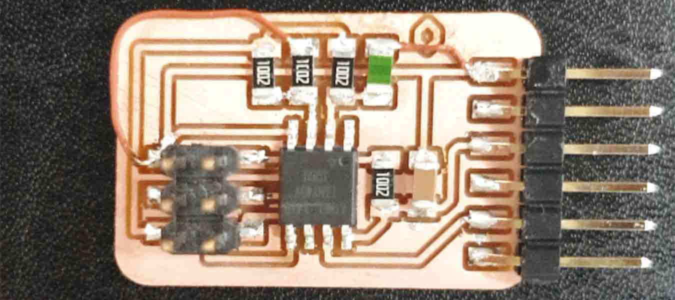
3. Soldering Component
- Componunt to use
- ATtiny45
- 1x6 Pin header
- 2x3 Pin header
- Capacitor 1uF SMD [1206]
- Resistor 10K SMD[1206] x4
- NTC Themistor 10K OHM
This time, I did milling based on the clearance.(0.15)
However, increasing the clearance makes soldering easier.
Check the subhead of this link, Coper Removal. Next time, I'll work on increasing the clearance.
Soldering
- NICE!!!
4. Programming For "Arduino
I proceeded with these two links in programming.g
Jihwam's Link / Embedded Programming Week Link
- AWESOME!!!
-----------------------------------------------(silence!!!! why!!!)---------------------------------------------------
- I looked at the board and circuit diagram and only a few hours later did I know why.
- That's the reason. Everyone, can you see this?
- I didn't see the circuit line hidden by that symbol! At first, I wondered about the circuit diagram, but I just made it! But it's not until now that I regret that I didn't dwell on that question more persistently.
- I AM JUMPER MASTER
↓Temperature Code in Arduino
#include <SoftwareSerial.h>
   const int rx=1;
   const int tx=2;
   const int tpin=3;
   SoftwareSerial mySerial(rx,tx);
   void setup() {
       mySerial.begin(9600);
   }

   void loop() {
       int t;
       t=analogRead(tpin);
       float tc=calcT(t);
       mySerial.println(tc);

   }

   float calcT(int data) {
       float B=3750;
       float T0=298.15;
       float R0=10000.0;
       float R1=11200.0;

       float rr1,t;
       rr1= R1 * data / (1024.0 - data);
       t = 1 / (log(rr1 / R0) / B + (1 / T0));
       return (float)(t - 273.15);
   }
This is the code I put on the temperature board. This code was helped on the website of Daisuke Doyo, an Academy student in 2018. His link
The code for using the str temperature sensor was extremely complex. I looked for a process that needed to be done before this code came out. Since the list is a variable list, we'll need to measure the history before we can calculate the property. However, the can't measure list directly, it can only measure the size. Will measure the voltage at a point between the thermistor and a knowledge register. Then, use The estimate for a voltage divider to calculate and finally convert the resistance of the thermistor to a temperature reading using the Steinhart-Hart equation. Then we get the temperature value we want.
It was really hard to understand this. I link this page with more explanations. If you can't solve your curiosity, you'd better keep that in mind.
The code above measures the temperature using the NTR and exports the value to the serial port (9600).
I took his code and used only the numbers tx and rx.
I tried again and this time faced with the "burn bootloader" problem.
Had to set the fuses on your board to get the serial debug working.
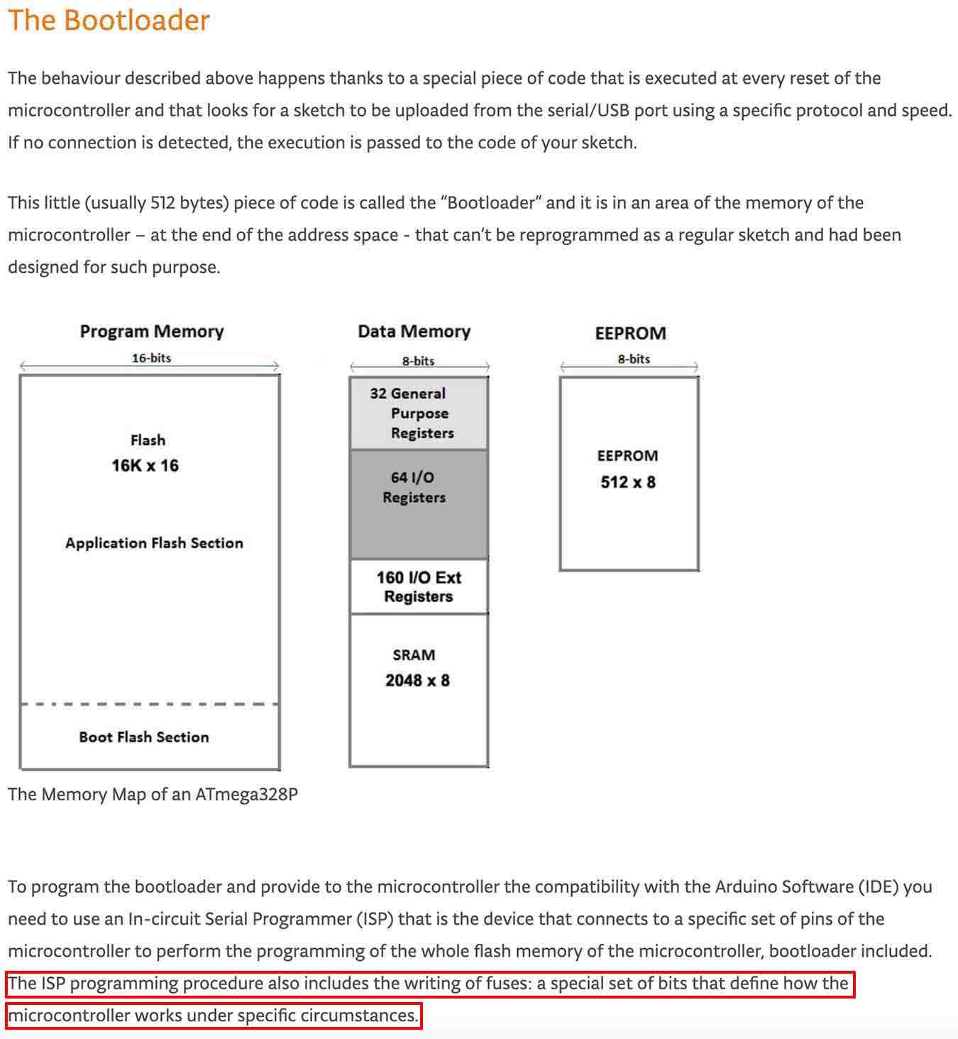
Thanks to this, I was able to see the fuse function of the "burn bootloader."
I went to the Tools in the Arduino program and fixed the fuse settings. The most important of them is the clock speed. The clock speed was set to 8MHz. And click Burn Bootloader to match the serial baud rate of my board and code.
The sensor worked when I solved the problem. The current temperature here is 28.6 degrees Celsius!
Additional Modification of Arduino Code
#include <SoftwareSerial.h>
const int rx=1;
const int tx=2;
const int tpin=3;
int sample;
int samplesize=5;

SoftwareSerial mySerial(1,2);
void setup() {
 mySerial.begin(9600);
}

void loop() {
   int t;
   t=analogRead(tpin);
   for (int x = 0; x < samplesize; x++) {
     t = t + sample;
     sample=analogRead(tpin);
   }
   float t = t / samplesize
   float tc=calcT(t);
   mySerial.println(tc);
   delay(1000);
}
float calcT(int data) {
 float B=3750;
 float T0=298.15;
 float R0=10000.0;
 float R1=11200.0;
 float rr1,t;
 rr1= R1 * data / (1024.0 - data);
 t = 1 / (log(rr1 / R0) / B + (1 / T0));
 return (float)(t - 273.15);
}
Modified code is a code that tells the average by counting five temperature values, then adding all of them and dividing them by five. In addition, it has set the delay to 1,000 microseconds.
This code has a large capacity, so if you want to use it, use ATtiny85 instead of ATtiny45.
4-4 File
Arduino
- week9_Temperature_Sencer.ino File here
- week9_Temperature_Sencer_ver2.ino File here
KiCad - Temperature Board
- WEEK9_Analog_Temperature_Senser_Board_0328 brd File here
- WEEK9_Analog_Temperature_Senser_Board_0328 sch File here
- WEEK9_Analog_Temperature_Senser_Board_0328-F_Cu.gbr File here
- WEEK9_Analog_Temperature_Senser_Board_0328-Edge_Cuts.gbr File here