Input Devices
Input Devices
| Characteristics | |
|---|---|
| Analog | measures continuously the variable and detects any proportional value between 100% and 0%. For this reason, the measure provided by the analog sensor is more precise than the one provided by the digital sensor. |
| Digital | only detects two possible status: if it is working at 100% or at 0%. |
| Logic | Part of digital sensor Expressed by 16 bits (Tip: If the data sheet is longer than 5 pages, it is a logic sensor.) |
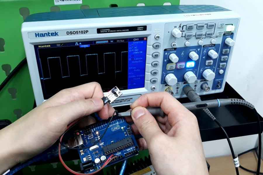
By using the oscilloscope, we measured the signals of each of the sensors: analog, digital, and logic sensors.
The images below shows our investigation.
Analog sensor
- Sensor used: Accelerometer sensor module(ADXL335 module)
- Sensor datasheet: ADXL335 datasheet
- How Accelerometer works?
- Photo:
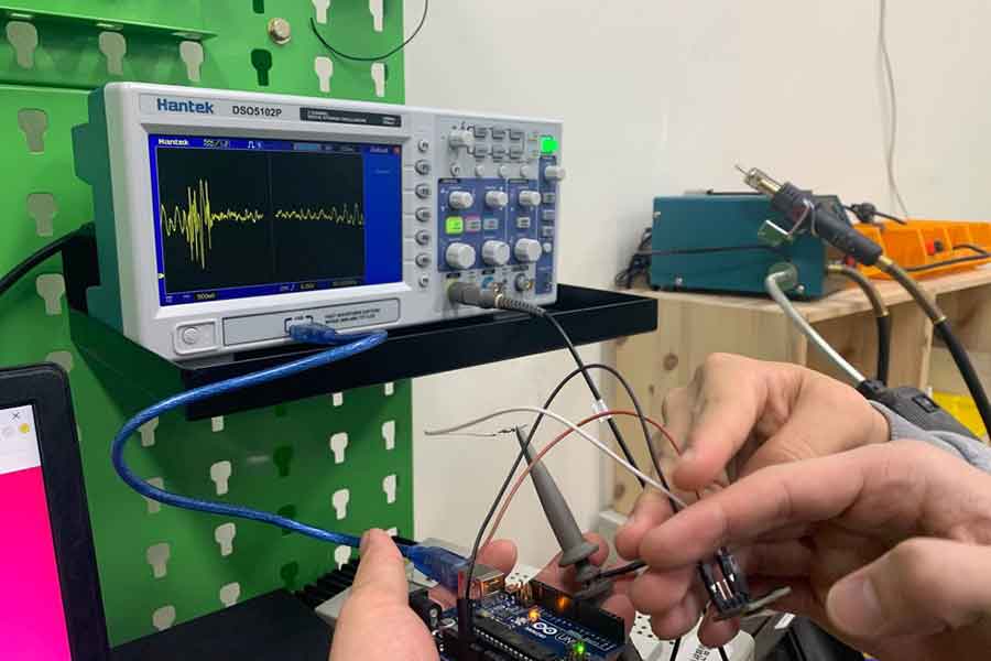
- Description of the graph:
Curvy line, looking like a trig graphs such as sine graph. - Explanation:
When we shake the sensor, the amplitude of the graph increases.
Digital sensor
- Sensor used: Infra-red light detector sensor(HC-SR501)
- Sensor datasheet: HC-SR501 datasheet
-
How HC-SR501 PIR Sensor Works :
If you didn’t know, all objects with a temperature above Absolute Zero (0 Kelvin / -273.15 °C) emit heat energy in the form of infrared radiation, including human bodies. The hotter an object is, the more radiation it emits.PIR sensor is specially designed to detect such levels of infrared radiation. It basically consists of two main parts: A Pyroelectric Sensor and A special lens called Fresnel lens which focuses the infrared signals onto the pyroelectric sensor.
PIR Sensor Working Pyroelectric Sensor Two Detection Slots A Pyroelectric Sensor actually has two rectangular slots in it made of a material that allows the infrared radiation to pass. Behind these, are two separate infrared sensor electrodes, one responsible for producing a positive output and the other a negative output. The reason for that is that we are looking for a change in IR levels and not ambient IR levels. The two electrodes are wired up so that they cancel each other out. If one half sees more or less IR radiation than the other, the output will swing high or low.
When the sensor is idle, i.e. there is no movement around the sensor; both slots detect the same amount of infrared radiation, resulting in a zero output signal.
But when a warm body like a human or animal passes by; it first intercepts one half of the PIR sensor, which causes a positive differential change between the two halves. When the warm body leaves the sensing area, the reverse happens, whereby the sensor generates a negative differential change. The corresponding pulse of signals results in the sensor setting its output pin high. (From lastminuteengineers)
- Photo:
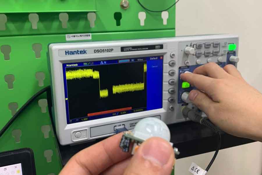
- Description of the graph:
Like a lego/square shape. There were no variations between two values – 0 and 1. The graph line is drawn and changes directions by 90 degrees. - Explanation:
There were only two values that we were able to measure/see on the oscilloscope’s screen – 0 and 1.
Logic sensor
- Sensor used: Digital temperature sensor module(DS18b20)
- Sensor datasheet: DS18b20 datasheet
- How DS18b20 Temperature Sensor Works : The basic answer is voltage varies with temperature or rather resistance varies with temperature. Resistance is a direct correlation. Voltage is inverse. 1) It works on the principle of direct conversion of temperature into digital value. 2) Its main features is change its bit numbers according to change in temperature. 3) Like, it changes bit in 9. 10 ,11,and 12 bits as temperature changes in values 0.5 °C . 0.25°C,1.25 and 0.0625°C respectively. 4) Its default bits value is 12 but it changes values according to temperature Change. 5) It has alarm and LCD as temperature changes alarms work and temperature value changes which we can get from lcd.
- Photo:
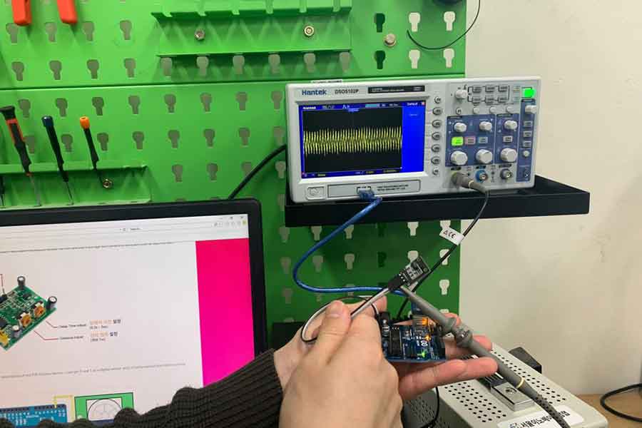
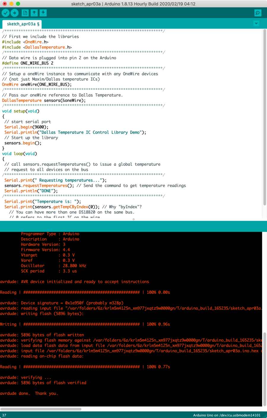
Noise was measured Because we without programming, we programmed it and measured it again.
/********************************************************************/
// First we include the libraries
#include <OneWire.h>
#include <DallasTemperature.h>
/********************************************************************/
// Data wire is plugged into pin 2 on the Arduino
#define ONE_WIRE_BUS 2
/********************************************************************/
// Setup a oneWire instance to communicate with any OneWire devices
// (not just Maxim/Dallas temperature ICs)
OneWire oneWire(ONE_WIRE_BUS);
/********************************************************************/
// Pass our oneWire reference to Dallas Temperature.
DallasTemperature sensors(&oneWire);
/********************************************************************/
void setup(void)
{
 // start serial port
 Serial.begin(9600);
 Serial.println("Dallas Temperature IC Control Library Demo");
 // Start up the library
 sensors.begin();
}
void loop(void)
{
 // call sensors.requestTemperatures() to issue a global temperature
 // request to all devices on the bus
/********************************************************************/
 Serial.print(" Requesting temperatures...");
 sensors.requestTemperatures(); // Send the command to get temperature readings
 Serial.println("DONE");
/********************************************************************/
 Serial.print("Temperature is: ");
 Serial.print(sensors.getTempCByIndex(0)); // Why "byIndex"?
   // You can have more than one DS18B20 on the same bus.
   // 0 refers to the first IC on the wire
   delay(1000);
}
- Description of the graph:
Looks like a digital graph, but we can adjust the pulse rate to send logic information The amplitude does not change. - Explanation:
The values repeat themselves inside a fixed range – 0 and 1.