Embedded Programming
Week 8 Embedded Programming Group Assignment
Compare the performance and development workflows for different microcontroller families. Document your work.
Table of Content: Pinout Diagram Clock Speed Internal clock External clock PWM (Pulse Width Modulation) (Not every pin can do PWM, find out which pin does that.) Absolute Maximum Ratings How “big” a program is in different languages (All those friendly Arduino libraries take up space.) Runtime
| Definition | ATtiny85 | |
|---|---|---|
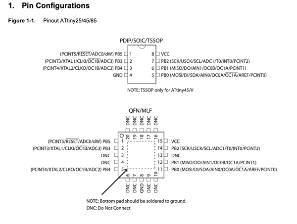
| Pinout Diagram | •A pinout is a reference to the pins or contacts that connect an electrical device or connector. It describes the functions of transmitted signals and the circuit input/output (I/O) requirements. •Each individual pin in a chip, connector or singular wire is defined in text, a table or a diagram. | (shown below in a bigger size) 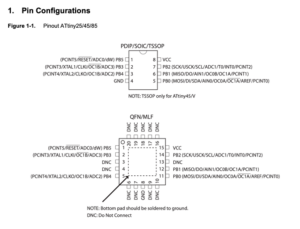 |
| Clock Speed | •The number of pulses per second •Generated by an oscillator that sets the tempo for the processor. •Usually measured in MHz (megahertz, or millions of pulses per second). | Max. 10 MHz Max. 20MHz Internal clock: 8.0 MHz +- 10% External clock: 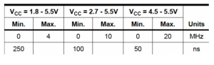 |
| PWM (Pulse Width Modulation) | •Used for controlling the amplitude of digital signals in order to control devices and applications requiring power or electricity. •It essentially controls the amount of power. •In the perspective of the voltage component, that is given to a device by cycling the on-and-off phases of a digital signal quickly and varying the width of the “on” phase or duty cycle. •A powerful benefit of PWM: power loss is very minimal. •Not every pin can do PWM •Find out which pin does that-> | Pin 1, Pin 0 can do PWM. 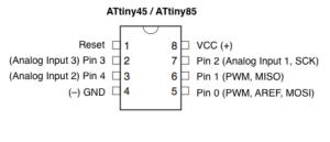 |
Absolute Maximum Ratings 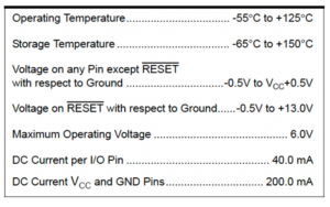 |
•Limiting values of operating and environmental conditions applicable to any electronic device of a specified type as defined by its published data •Should not be exceeded under the worst probable conditions. •These values are chosen by the device manufacturer to provide acceptable serviceability of the device •taking no responsibility for equipment variations, environmental variations, and the effects of changes in operating conditions due to variations in the characteristics of the device under consideration and of all other electronic devices in the equipment. •Stresses above those listed under AMR may cause permanent damage to the device. | |
| Runtime | Runtime = Run time = Execution time •the time when the CPU is executing the machine code. | Scratch: approx.. 2.1 seconds Arduino: C: |
| (program size) | C < C# « Scratch < Arduino 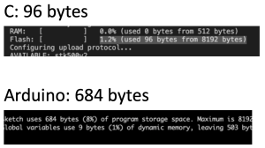 |
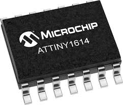
The ATTINY family operates from 3.3V to 5V. Typically, ATtiny1614 is an 8bit MCU, for example, with a total of 14 pins that can be programmed through UPDI. Clock speed is 20 MHz. It can be used in various voltages of 3.3V to 5.5v.
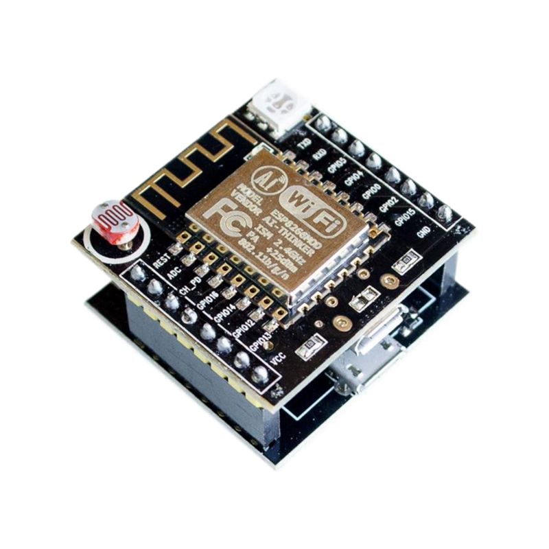
The advantage of Esp Module is that it supports SPI network and Wi-Fi is available. It has large flash memory (4MB). The disadvantage is that programming speed is slow. The ESP operates at 3.3V and burns at higher voltages, so be careful. For each pin GPIO, it is possible to support VSPI such as digital pin PWM.
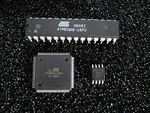
The Atmel 8-bit AVR RISC-based microcontroller combines 32 KB ISP flash memory with read-while-write capabilities, 1 KB EEPROM, 2 KB SRAM, 23 general purpose I/O lines, 32 general purpose working registers, three flexible timer/counters with compare modes, internal and external interrupts, serial programmable USART, a byte-oriented 2-wire serial interface, SPI serial port, 6-channel 10-bit A/D converter (8-channels in TQFP and QFN/MLF packages), programmable watchdog timer with internal oscillator, and five software selectable power saving modes. The device operates between 1.8-5.5 volts. The device achieves throughput approaching 1 MIPS per MHz.
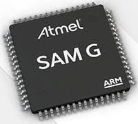
32-bit ARM-Based Microcontrollers
The SAM D21 is a series of low-power microcontrollers using the 32-bit ARM®Cortex®-M0+ processor,
and ranging from 32- to 64-pins with up to 256KB Flash and 32KB of SRAM. The SAM D21 operate at a
maximum frequency of 48MHz and reach 2.46 CoreMark®
/MHz. They are designed for simple and
intuitive migration with identical peripheral modules, hex compatible code, identical linear address map
and pin compatible migration paths between all devices in the product series. All devices include
intelligent and flexible peripherals, Event System for inter-peripheral signaling, and support for capacitive
touch button, slider and wheel user interfaces.
Programming
ISP
In-system programming (ISP), also called in-circuit serial programming (ICSP), is the ability of some programmable logic devices, microcontrollers, and other embedded devices to be programmed while installed in a complete system, rather than requiring the chip to be programmed prior to installing it into the system. It allows firmware updates to be delivered to the on-chip memory of microcontrollers and related processors without requiring specialist programming circuitry on the circuit board, and simplifies design work.
UPDI
The Unified Program and Debug Interface (UPDI) is a proprietary interface for external programming and on-chip debugging of a device. It is a successor to the PDI 2-wire physical interface, which is found on all AVR® XMEGA devices. UPDI is a single-wire interface providing a bi-directional half-duplex asynchronous communication with the target device for purposes of programming and debugging.
FTDI
Future Technology Devices International, commonly known by its acronym FTDI, is a Scottish privately held semiconductor device company, specialising in Universal Serial Bus (USB) technology.[1] It develops, manufactures, and supports devices and their related software drivers for converting RS-232 or TTL serial transmissions to USB signals, in order to allow support for legacy devices with modern computers.[2] FTDI provides application-specific integrated circuit (ASIC) design services. They also provide consultancy services for product design, specifically in the realm of electronic devices.
OTA
Over-the-Air programming (OTA) refers to various methods of distributing new software, configuration settings, and even updating encryption keys to devices like mobile phones, set-top boxes or secure voice communication equipment (encrypted 2-way radios). One important feature of OTA is that one central location can send an update to all the users, who are unable to refuse, defeat, or alter that update, and that the update applies immediately to everyone on the channel. A user could “refuse” OTA but the “channel manager” could also “kick them off” the channel automatically.