11. Output Devices
Assignment
Group assignment
- Measure the power consumption of an output device
- Document your work (in a group or individually)
Group Project here
Individual Assignment
- Add an output device to a microcontroller board you've designed and program it to do something
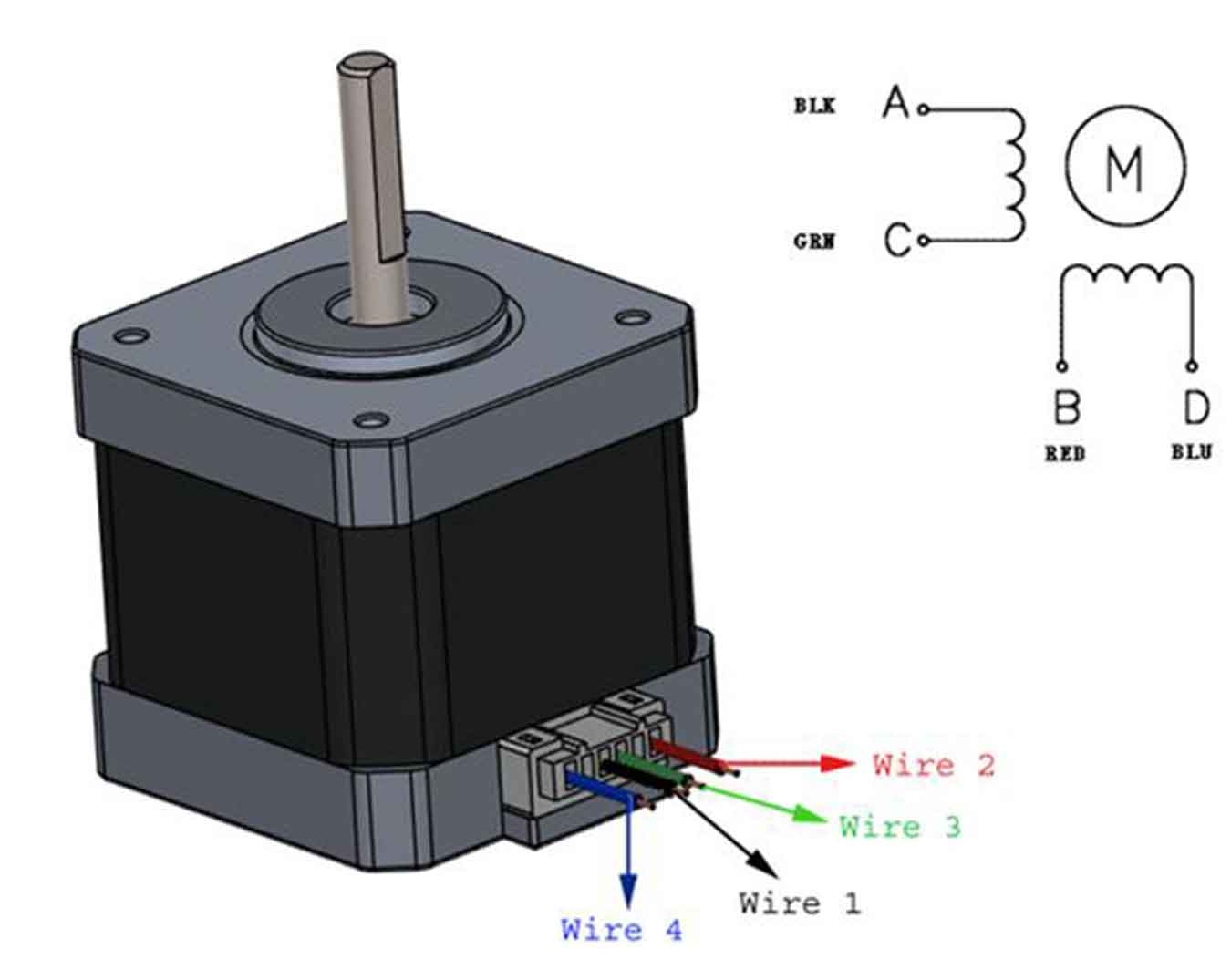
- Stepper Motor-NEMA17
Table of Contents
1. Select Output Device For Final Project (Stepper Motor_NEMA17)
2. Board Conception
2-1 Conception
2-2 Reference
2-1 Conception
2-2 Reference
3. Design Microcontroller Board
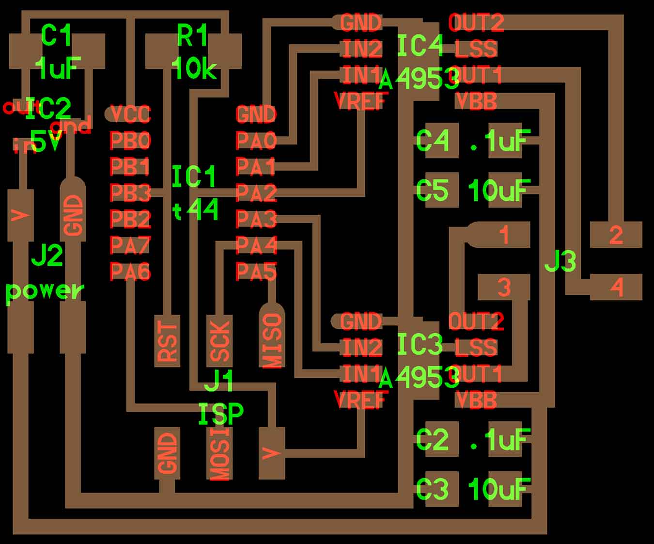
3-1. Schematic
3-2. PCB
3-1. Schematic
3-2. PCB
4. Milling & Soldering Component
5. Programming For "Arduino"
1. Select Output Device For Final Project
- I anticipate the use of the following output device…
- Stepper Motor_NEMA17 : It will move the mechanical elements of my project (leg parts)
Stepper Motor_Datasheet Of NEMA17
2. Board Conception
2-1. Conception
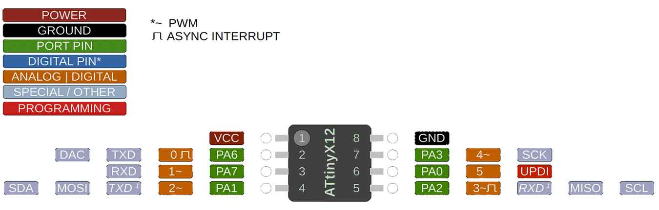
- I will make an MCU that includes a motor driver that can move a stepper motor. Also, Neil's board used ATtiny44, but I'm thinking of using ATtiny412. In addition, a button will be added.
2-2. Reference
- I referred to Neil's motor board and hello412 boards and atiny412 pinout.
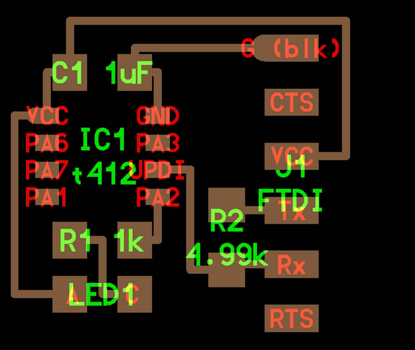
↓Neil's Stepper Motor Board
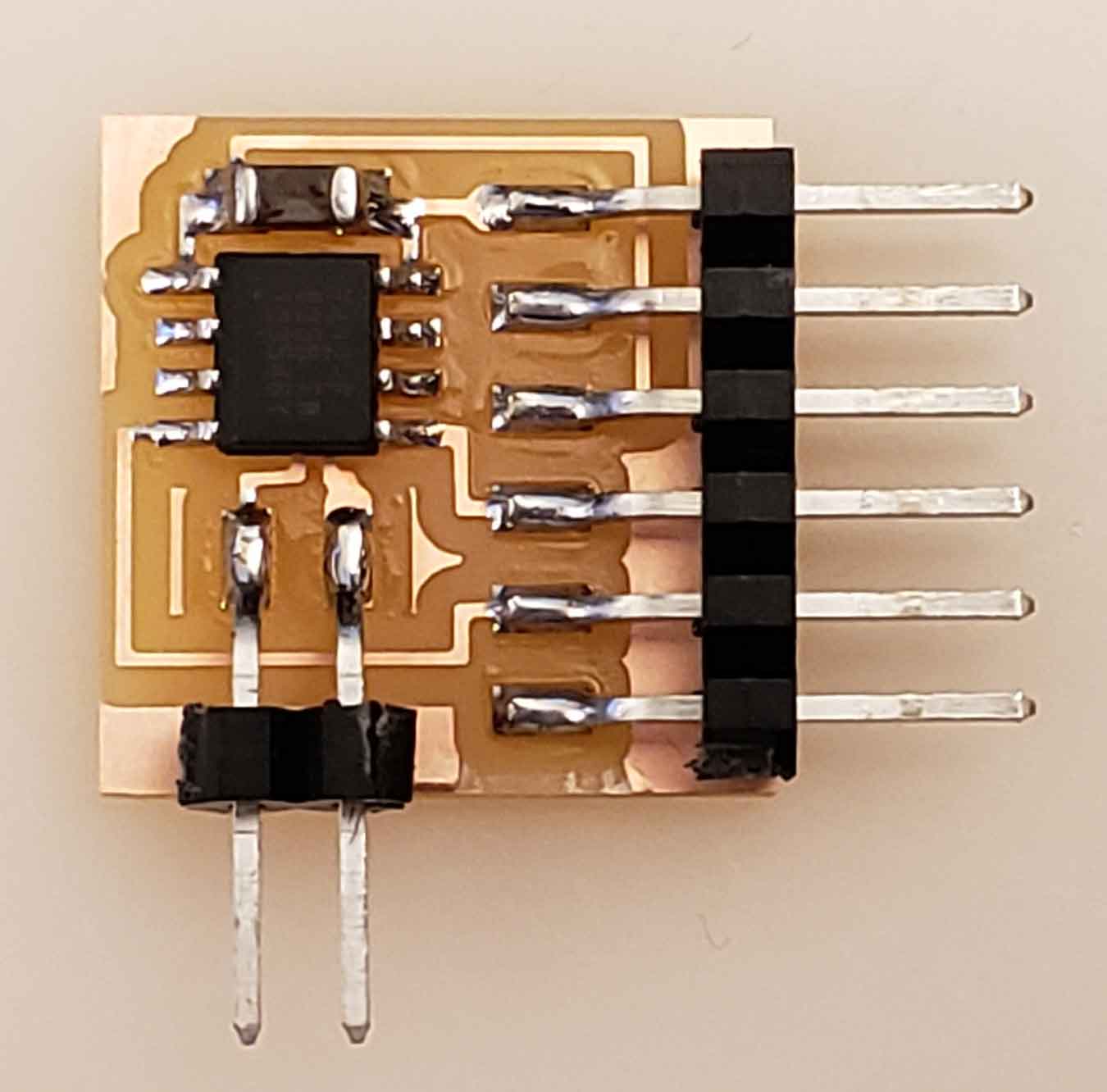
↓Neil's ATtiny412 Blink
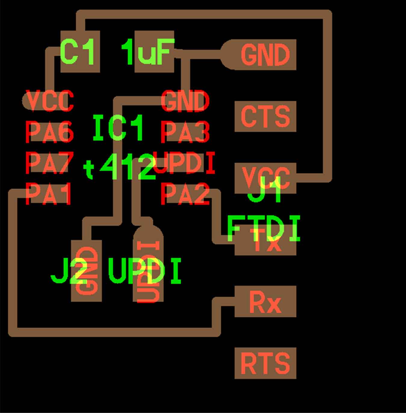
↓Neil's ATtiny412 echo
↓ATtiny412 Pinout
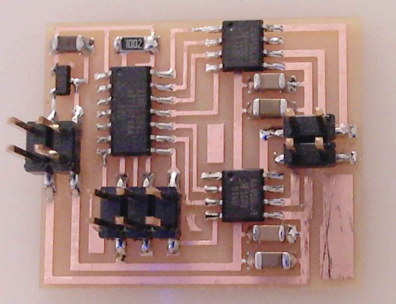
3. Design Microcontroller Board
3-1. Schematic
- I schematized my board by referring to Neil's board.
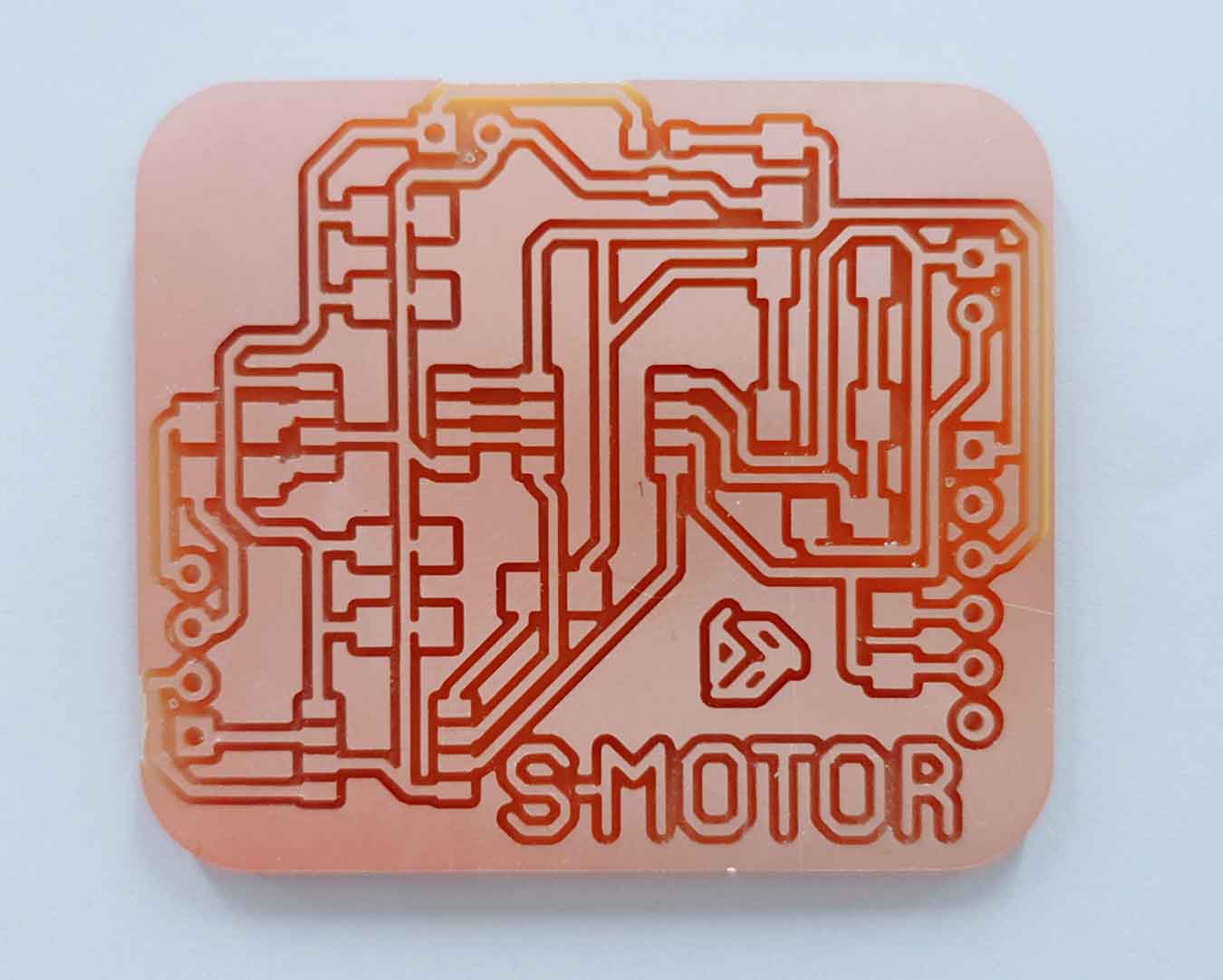
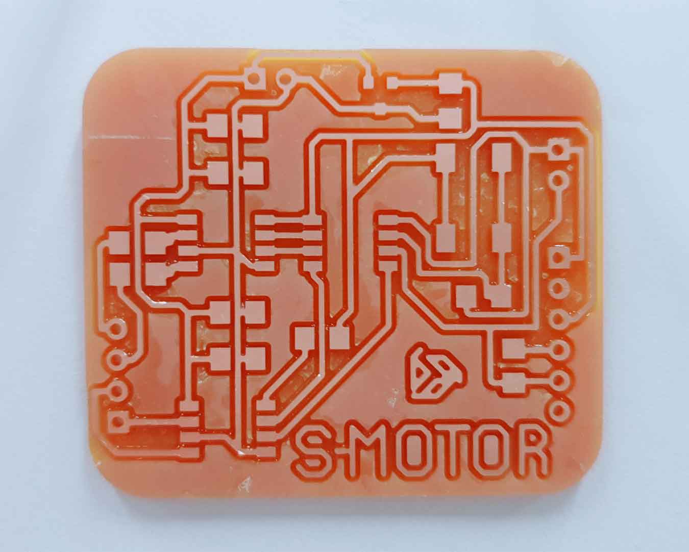
3-2. PCB
- It is a PCB design. In the middle, there were three places where experience was impossible. I solved it by putting in three jumpers.
PCB Trace Width Calculator
The motor wants more current than other components on the board. …Trace Width to allow for this extra current and prevent the traces from overheating. Add some values on this site to get the thickness you need.PCB Trace Width Calculator
4. Milling & Soldering Component
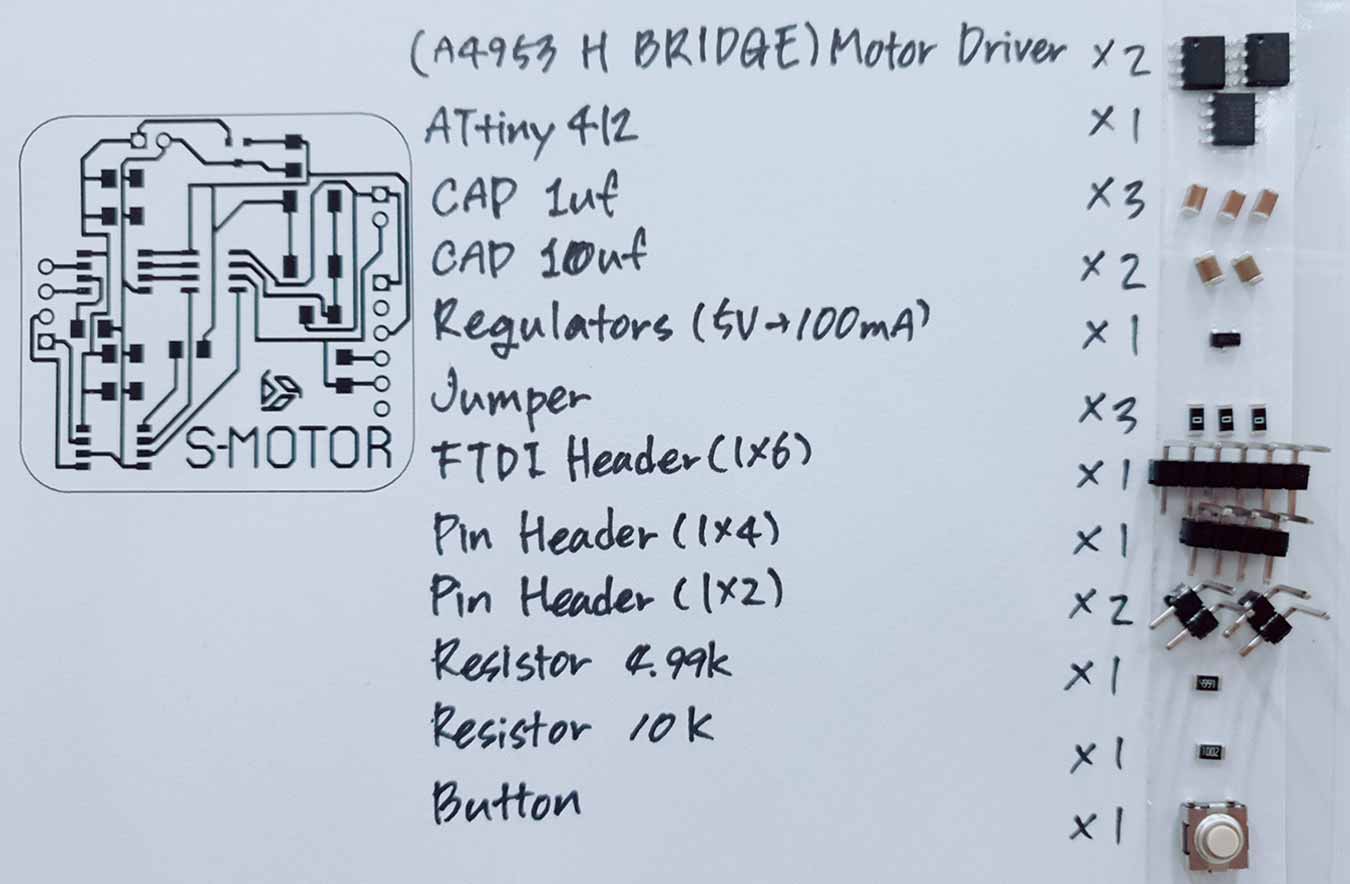
- Componunt
- x2 Motor Driver(A4953 H Bridge)
- x1 ATtiny412
- x3 Capacitor 1uf
- x2 Capacitor 10uf
- x1 Regulators(to 5V)
- x3 Jumper
- x1 FTDI Header(1x6)
- x1 Pin Header(1x4)
- x2 Pin Header(1x2)
- x1 Resistor 4.99K
- x1 Resistor 10K
- x1 Button
↓Soldering Process
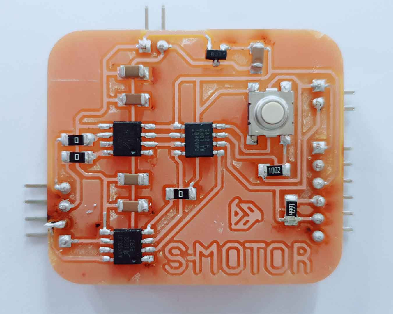
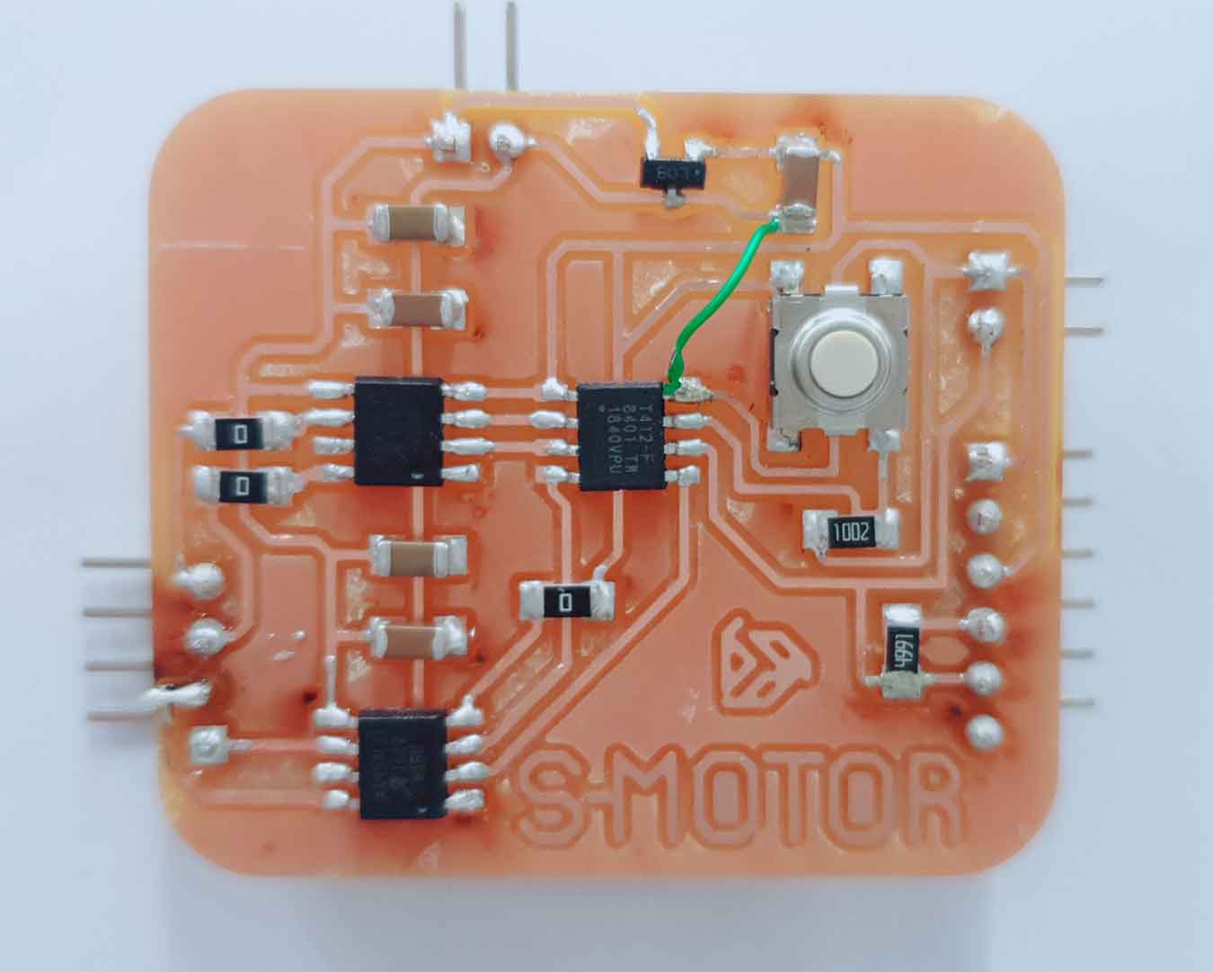
- After the milling, there was a metal pad under the motor driver I used, so I had to take all the extra copper off.
- During soldering, I checked where the gnd was not connected and lastly connected using a wire jumper.
5. Programming For "Arduino"
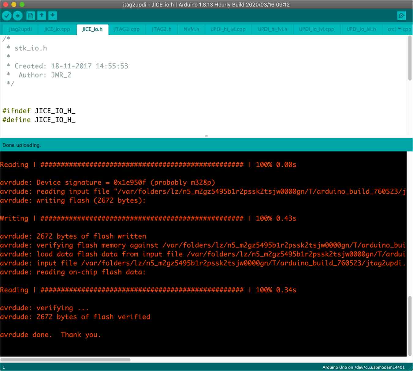
Since 412 has an updi, to program here, download the "jtag2updi aduino"-related aduino code into the aduino to which the board will be connected first.
I followed this GitHub link by referring to the tutorial.
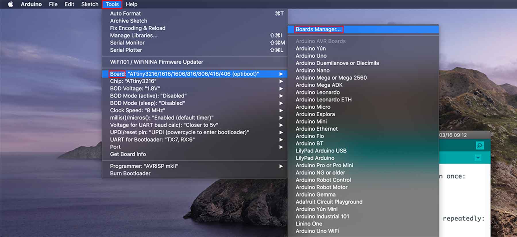
In the tool - board - board manager. Click.
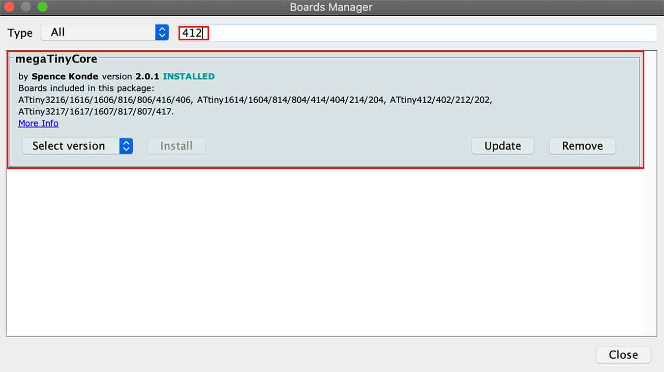
Type 412 in the search bar. Find Megatinycore, which includes attiny412. Download this.
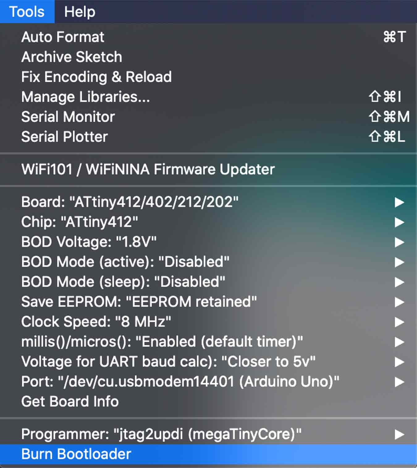
…board you created, set the fused using the burn bootloader button and insert the motor code.
- Set the tool as above and insert the code.
Code below was written by Yuxuan , I used it to test my motor was working.
↓Motor Code in Arduino
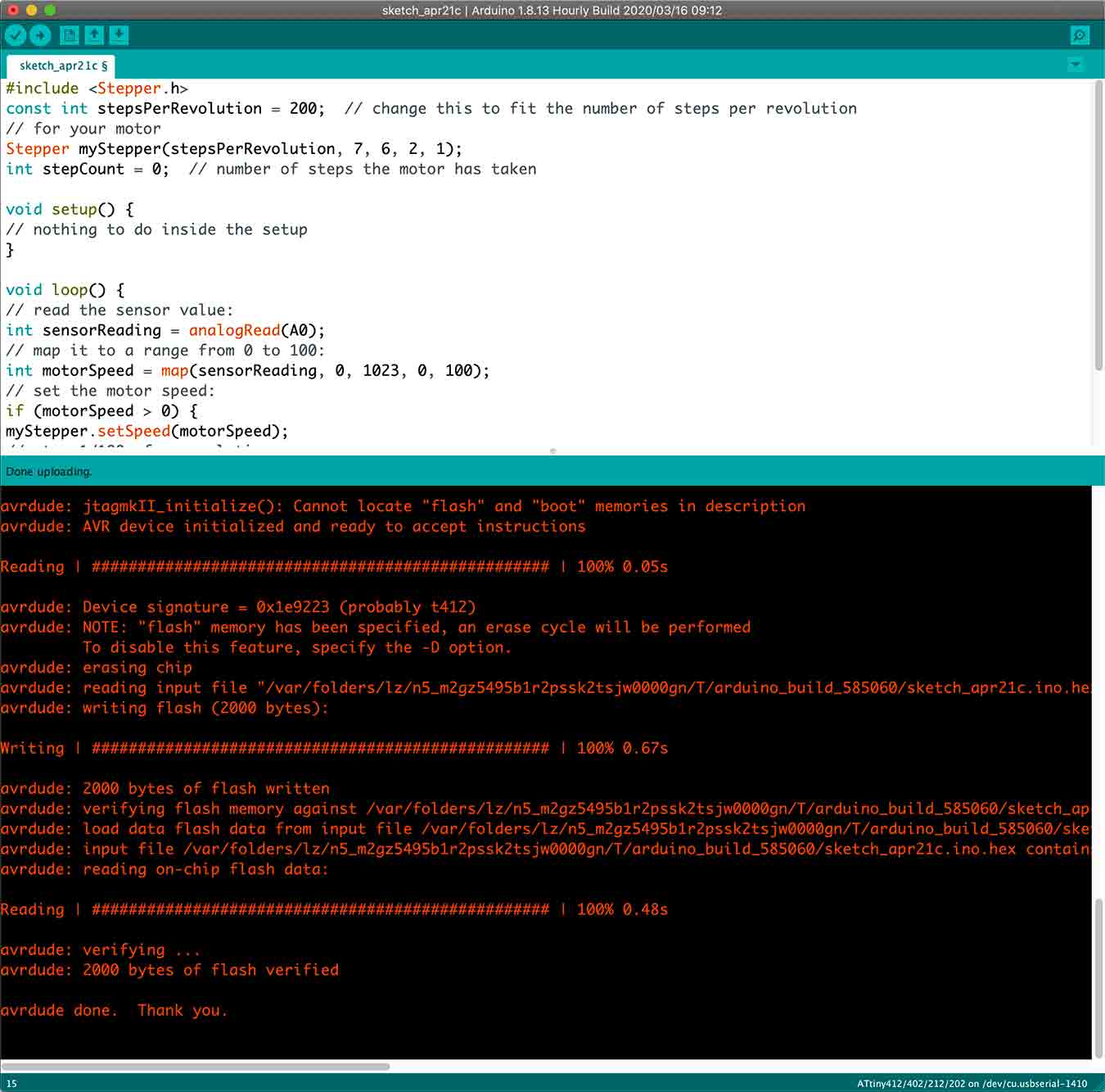
- If you put the code in so successfully......
- If you use the power supply to give a voltage of 10 volts.....
- It Doesn't Work.
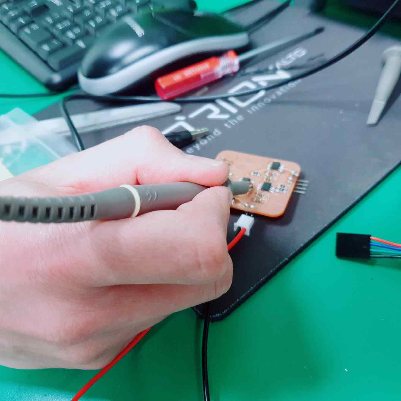
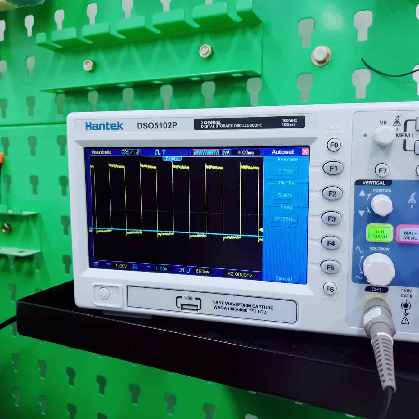
- So I use an oscilloscope. I checked the signals of the four pins connected to the motor, but only two were confirmed.
- The reason is that the pin number in the code is wrong, so what if we fix the pin number and make it work again?
- It Doesn't Work.
Trial and error to operate the motor
- I looked up the principle of how Stepper Motor(NEMA17) works through datasheet and found out that there is a problem with the code after that. So I changed the code and put it in.
↓An altered code
I successfully activated the motor. However, it didn't work smoothly and I found out that there was a problem with the code again.
digitalWrite (DriverA_1, a1);
digitalWrite (DriverA_2, a1);
digitalWrite (DriverB_1, a1);
digitalWrite (DriverB_2, a1);
This code stops the motor. The motor stops by powering both drivers.
Because these codes are included, turning and stopping. That's why it spins roughly, not smoothly.
↓2nd An altered code (Kaz's Stepper Motor Code)
This code has removed the middle stop step.
So I solved the rough spin.
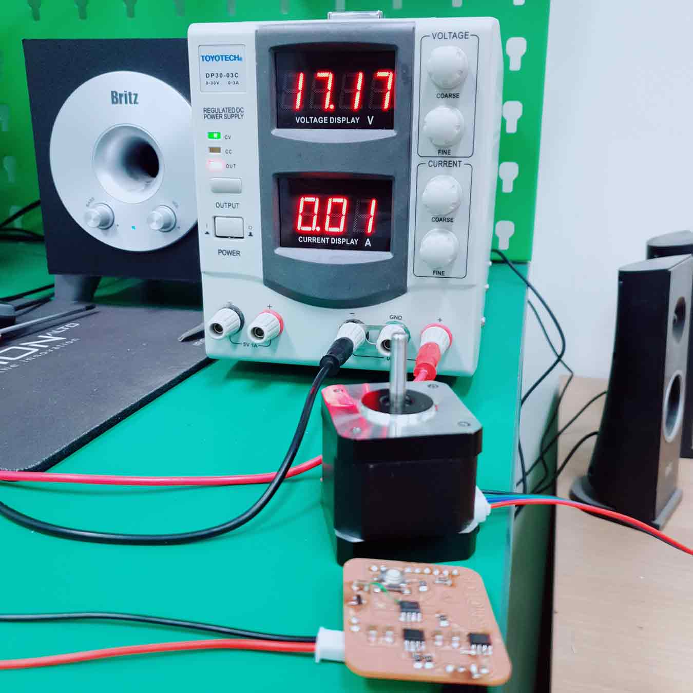
The second code is successful. It works very smoothly in one direction as I want.
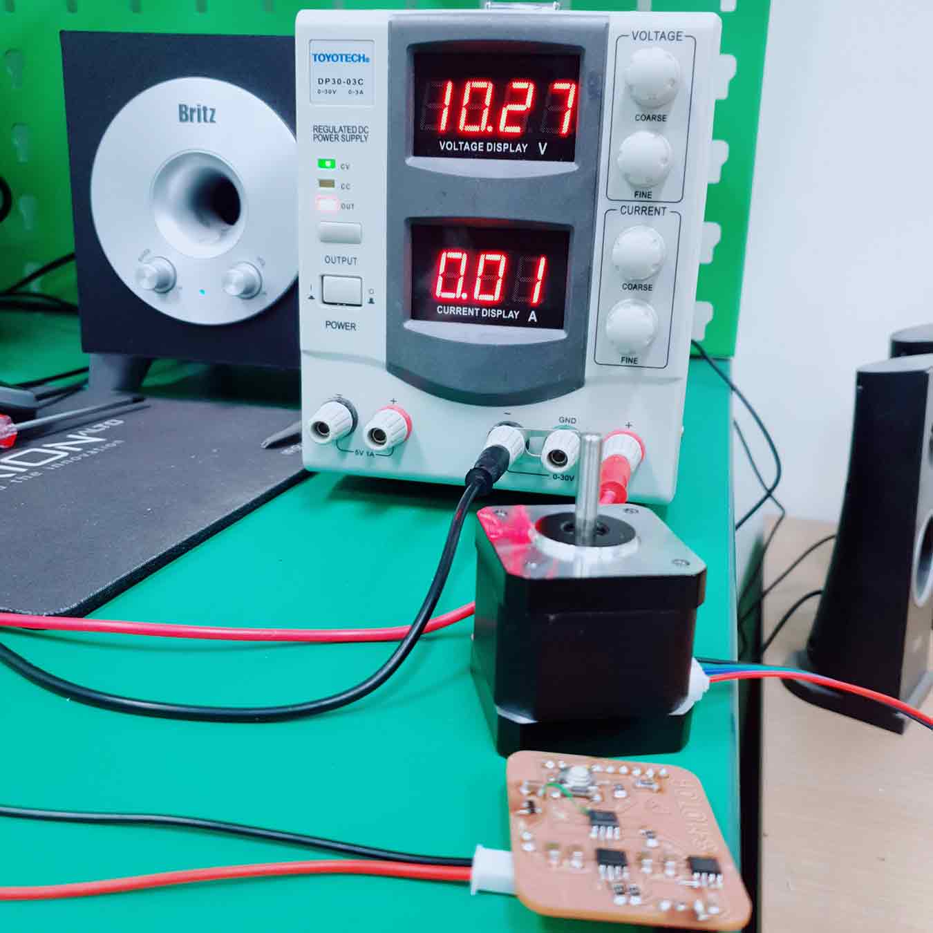
- It worked at 8V, but it moved roughly. It's just like the first one. But I didn't stop there, and I raised the voltage to 14V and the motor ran smoothly.
- If you check the result by putting in the second cord, it is assumed that the reason the motor was rough when you put in the first cord that was fixed was probably the lack of power.
Additional...
Link to the regulator LM3480 datasheet I used
I looked at Neil's board, and I put one regulator and one capacitor in the direction of the mcu.
Later when I looked at the data sheet, I realized that I had to attach a capacitor on both sides of one regulator. This time we have succeeded like this, but the next chance we will make boards with additional capacitors on both sides for safety.
File
Arduino
- week11_turn_succes_not_smooth.ino File here
- week11_turn_succes_smooth.ino File here
KiCad
- week11_stepper_moter_NEMA17.brd File here
- week11_stepper_moter_NEMA17.sch File here
- week11_stepper_moter_NEMA17-Edge_Cuts.gbr File here
- week11_stepper_moter_NEMA17-F_Cu.gbr File here
- week11_stepper_moter_NEMA17.drl File here