8. Embedded Programming
Assignment
Group assignment
- Compare the performance and development workflows for other architectures
Group Project here
Individual Assignment
- Read a microcontroller data sheet.
- Program your board to do something, with as many different programming languages and programming environments as possible.
Table of Contents
1. Read Data Sheet
1-1 Pinout Schematics
1-2 Clock Speed
1-3 PWM(Pulse Width Modulation)
1-1 Pinout Schematics
1-2 Clock Speed
1-3 PWM(Pulse Width Modulation)
2. My Board
3. Programming For "Arduino"
3-1 Embedded Programming Example File("Button")
3-2 Self Coding(Modify Existing Code)
3-3 File
3-1 Embedded Programming Example File("Button")
3-2 Self Coding(Modify Existing Code)
3-3 File
4. Programming For "C"
4-1 PlatformIO IDE Setting
4-2 Conection
4-3 Coding(Reference Instructables Circuits Site)
4-4 File
4-1 PlatformIO IDE Setting
4-2 Conection
4-3 Coding(Reference Instructables Circuits Site)
4-4 File
1. Read Data Sheet
1-1 Pinout Schematics :
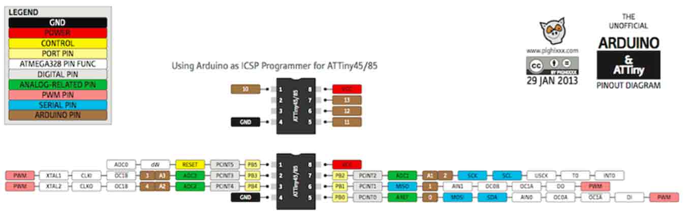
- Pinout schematics is very important. We can check the Supply voltage, Ground, output number of each pin by looking at the picture.
- Checking this is very useful when you drawing a circuit diagram, when you connecting each componant, and when you coding somthing.
1-2 Clock Speed :
Max. 10 MHz / Max. 20MHz / Internal clock: 8.0 MHz +- 10% / External clock: -
- EXPLAN : All parts operate in accordance with the electrical signals produced at a constant interval (speed), which is 'clock'.
* Hz : indicates how many signals were generated per second.(One signal per second, 1 Hz.)
For example
3 Hz: 3 times per second.
3 MHz: 3 million times.
3 GHz: 3 billion cycles produce a digital signal of 0 and 1.
Increasing this unit means increasing the clock count. Indicates that your computer is processing faster.
1-3 PWM(Pulse Width Modulation) :
- EXPLAN :The role is to simulate analog signals by quickly changing digital signals by adjusting the cycle of On/Off on the hardware.
- So in the case of attiny85, PWM is PB1 and PB2.
2. My Board
- I checked my board that I made in the 6th week before the embedded programming.
- What to Know before programming about my board
- Microcontroller : ATtiny85
- LED Pin = 3
- Button Pin = 4
3. Programming For "Arduino"
3-1 Embedded Programming Example File("Button")
- Must add ATtinyCore in the board manager to read ATtiny85. I finished this course in week6 (Click ATinycore Download & Programming) .
- Turn on the arduino and set the board, chip, and programmer on the tool.
- And use Examples > Digital > "Button".
There was a problem with the board. No code will be entered.
I could find out what the problem is through FTDI module.
When I insert the code, the lid of the ftdi module lights up, but I didn't. Here you can expect problems of tx and rx.
I looked at my board design. Exactly. In my board design, I connected tx and rx incorrectly. I solved the problem by connecting tx and rx through jumper wire.
- Operation!
3-2 Self Coding(Modify Existing Code)
↓Morse Code Ver. English
I wrote the "F A B" code by referring to this Morse code table. By modifying the button code.
I used the button as pin 4 and the LED as pin 3. In pin-out, the button was set as input and the LED was used as output.
And using if statement within the loop, I set the Morse code I wanted to flash when the button was high.
The word I wanted to make Morse code was FAB. To represent the Morse code, different lengths of light must be used, and I set the short signal to the HIGH state, 500 ms long (D), and then set the middle gap to 500 ms. The long signal was set at 2000 ms in the HIGH state.
- Verify and success
Morse code has a short and long signal of light.I used a delay to distinguish it. If a digital signal is delayed between HIGH and LOW, the output is maintained as much as the delay. Therefore, I set the delay to 500ms for short signals, and the long signals to 2000ms, which is four times that.
- Morse Code Settings
- The length of a short signal : 500ms
- The length of a long signal : 2000ms
- The length between signal : 500ms
- Interval of the entire Morse Code signal : 5000ms
3-3 File
- Arduino File here
4. Programming For "C"
4-1 PlatformIO IDE Setting
The PlatformIO IDE : A toolset for embedded C/C++ development
- First, turn on vscode and download the PlatformIO IDE from extensions.
- Create a new project along the red box.
4-2 Conection
- Correct connection is very important!(The red module is the FTDI module. My board, which is connected to this, was designed by changing the tx,rx order. So I took the jumper wire and crossed it again and connected it with FTDI.) I borrowed Jihwan's ISP and connected. Jihwan's Link
4-3 Coding(Reference Instructables Circuits Site)
- I wanted a code that had an LED stuck in it, and I found the code on this site while I was
- Download the "Blink in C.txt", modify the LED pin.
- Build(1) and Upload(2)!
- Success!!
- Although C language programming and embedded is difficult, PlatformIO IDE has dramatically shortened the process.
4-4 File
- main.c File here
- main 2.c File here
- Button_FAB_TO_MOS_.ino File here
- Button_FAB_TO_MOS_2.ino File here