WIFI Networking
Here is our group works : week15
This week, I connected the Wi-Fi network using ESP32-CAM and streamed it to a web page.
Linked to the group assignment page
● Documented your project.
● Documented what you have learned from implementing networking and/or communication protocols
● Explained the programming process/es you used.
● Outlined problems and how you fixed them
● Included design files (or linked to where they are located if you are using a board you have designed and fabricated earlier) and original code.
First of all, when we talk about how Wi-Fi networking works, we can say that Wi-Fi networking is a structure that consists of services, protocols, and addresses to exchange information. My challenge is, for example, a service can be an ESP32-CAM video, and streaming to a website is also a service. Addresses are required for each service, where the third number in the AP is the same bundle and the last number is the address of each object (for example, 1 in the address 192.168.1.213 represents a category of the same network and 213 is each address).
To put it simply, the port that a deliveryman sends to transmit video can be called a service, and although each delivery address from the deliveryman's work address to another address, the zones can be the same.
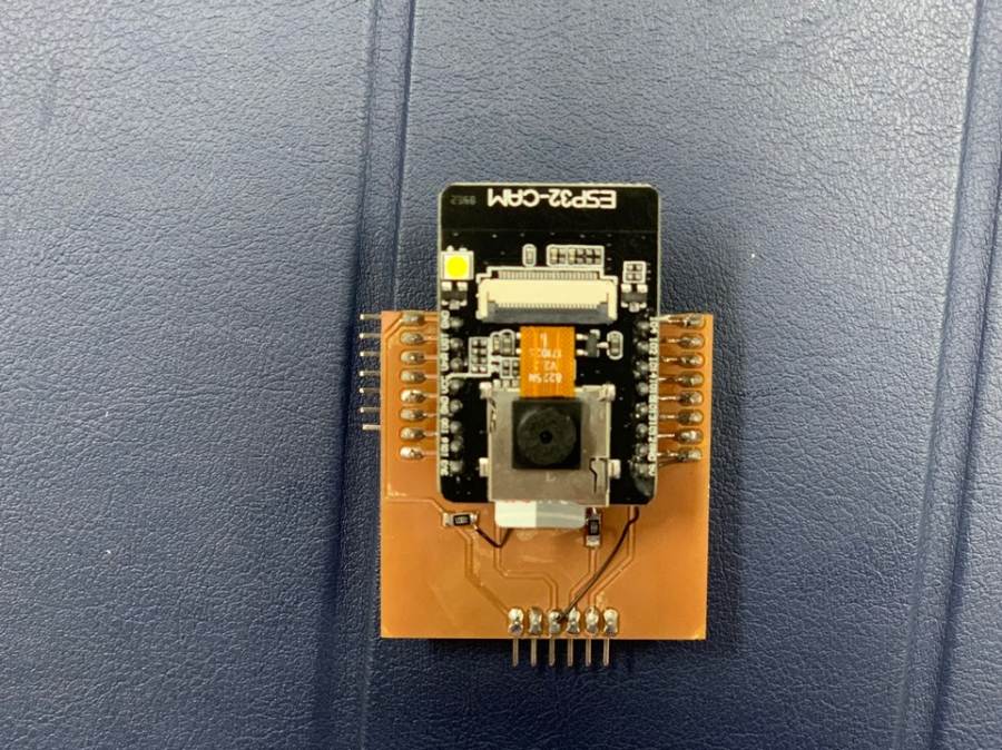
This is the ESP32-CAM board for this final project.
MCU with Wi-Fi connectivity, programming speed is a bit slow, but... I'm going to do a project that uses this board to stream time slowly.
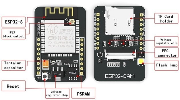
It refers to the structural features of ESP32-CAM. SD card can be used, Reset button is at the back, and Flash lamp also has. The lamp flashes when the reset button is pressed or the board is activated.
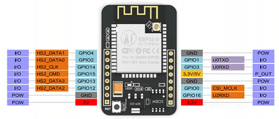
It is the pinout of esp32-CAM. There are three GND pins and two power pins (3.3V or 5V).
GPIO 1 and GPIO 3 are serial pins.
This pin is required to upload code to the board.
GPIO 0 also plays an important role because it determines whether ESP32 is in flash mode.
ESP32 flashes when GPIO 0 is connected to the GND.
The following pins are internally connected to the microSD card reader:
GPIO 14: CLK
GPIO 15: CMD
GPIO 2: Data 0
GPIO 4: Data 1 (also connected to the on-board LED)
GPIO 12: Data 2
GPIO 13: Data 3
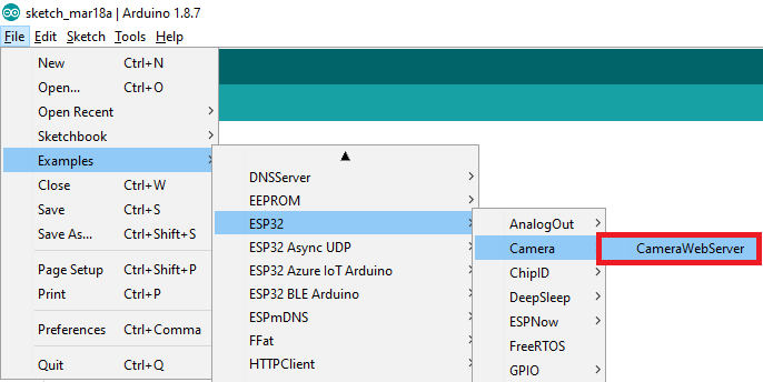
Webstreaming codes can be obtained directly from the aduino example. The code below is an example.
#include "esp_camera.h"
#include <WiFi.h>

//
// WARNING!!! Make sure that you have either selected ESP32 Wrover Module,
//            or another board which has PSRAM enabled
//

// Select camera model
//#define CAMERA_MODEL_WROVER_KIT
//#define CAMERA_MODEL_ESP_EYE
//#define CAMERA_MODEL_M5STACK_PSRAM
//#define CAMERA_MODEL_M5STACK_WIDE
#define CAMERA_MODEL_AI_THINKER

#include "camera_pins.h"

const char* ssid = "이노베이션팹랩_2G";
const char* password = "innovationpark";

void startCameraServer();

void setup() {
  Serial.begin(115200);
  Serial.setDebugOutput(true);
  Serial.println();

  camera_config_t config;
  config.ledc_channel = LEDC_CHANNEL_0;
  config.ledc_timer = LEDC_TIMER_0;
  config.pin_d0 = Y2_GPIO_NUM;
  config.pin_d1 = Y3_GPIO_NUM;
  config.pin_d2 = Y4_GPIO_NUM;
  config.pin_d3 = Y5_GPIO_NUM;
  config.pin_d4 = Y6_GPIO_NUM;
  config.pin_d5 = Y7_GPIO_NUM;
  config.pin_d6 = Y8_GPIO_NUM;
  config.pin_d7 = Y9_GPIO_NUM;
  config.pin_xclk = XCLK_GPIO_NUM;
  config.pin_pclk = PCLK_GPIO_NUM;
  config.pin_vsync = VSYNC_GPIO_NUM;
  config.pin_href = HREF_GPIO_NUM;
  config.pin_sscb_sda = SIOD_GPIO_NUM;
  config.pin_sscb_scl = SIOC_GPIO_NUM;
  config.pin_pwdn = PWDN_GPIO_NUM;
  config.pin_reset = RESET_GPIO_NUM;
  config.xclk_freq_hz = 20000000;
  config.pixel_format = PIXFORMAT_JPEG;
  //init with high specs to pre-allocate larger buffers
  if(psramFound()){
    config.frame_size = FRAMESIZE_UXGA;
    config.jpeg_quality = 10;
    config.fb_count = 2;
  } else {
    config.frame_size = FRAMESIZE_SVGA;
    config.jpeg_quality = 12;
    config.fb_count = 1;
  }

#if defined(CAMERA_MODEL_ESP_EYE)
  pinMode(13, INPUT_PULLUP);
  pinMode(14, INPUT_PULLUP);
#endif

  // camera init
  esp_err_t err = esp_camera_init(&config);
  if (err != ESP_OK) {
    Serial.printf("Camera init failed with error 0x%x", err);
    return;
  }

  sensor_t * s = esp_camera_sensor_get();
  //initial sensors are flipped vertically and colors are a bit saturated
  if (s->id.PID == OV3660_PID) {
    s->set_vflip(s, 1);//flip it back
    s->set_brightness(s, 1);//up the blightness just a bit
    s->set_saturation(s, -2);//lower the saturation
  }
  //drop down frame size for higher initial frame rate
  s->set_framesize(s, FRAMESIZE_QVGA);

#if defined(CAMERA_MODEL_M5STACK_WIDE)
  s->set_vflip(s, 1);
  s->set_hmirror(s, 1);
#endif

  WiFi.begin(ssid, password);

  while (WiFi.status() != WL_CONNECTED) {
    delay(500);
    Serial.print(".");
  }
  Serial.println("");
  Serial.println("WiFi connected");

  startCameraServer();

  Serial.print("Camera Ready! Use 'http://");
  Serial.print(WiFi.localIP());
  Serial.println("' to connect");
}

void loop() {
  // put your main code here, to run repeatedly:
  delay(10000);
}
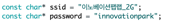
When connecting Wi-Fi, put the Wi-Fi name and password around you and set it up. And after upload, you can see the address through Wi-Fi connection on the serial monitor.
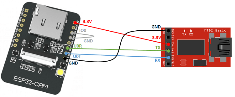
When uploading ESP32-CAM, there is an important point.
GND and GPIO0 must always be connected to upload programs.
Also, even if 5V is inserted into the module, the TX/RX is manufactured to change 3.3V, so no voltage divider is required.
So I made a voltage divider on my board and used the jumper again.
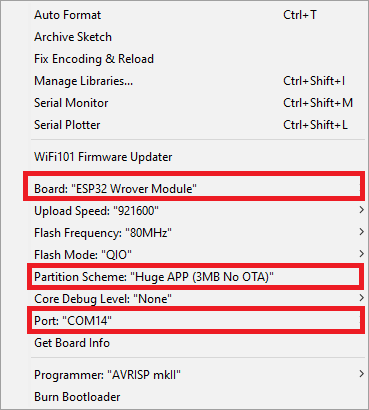
Use the Esp32 Uber Module and upload the Partition Scheme to the Huge APP. Occasionally, errors of memory overrun occurred when uploading when it was not Huge APP. If it happens, change it as above.

Upload completed. Let's check the serial monitor.
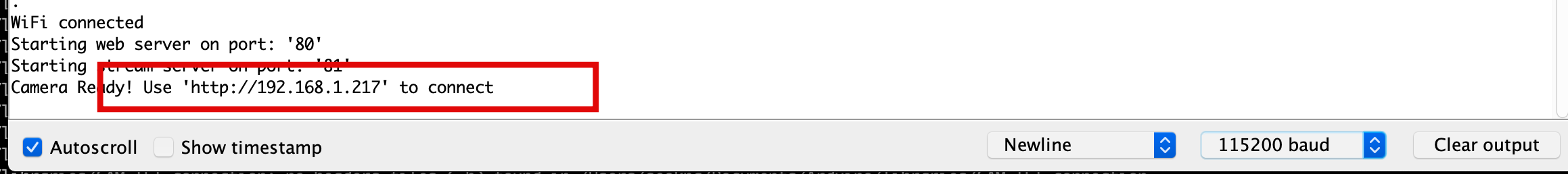
I could copy the address from the serial monitor and stream it to the Internet link.
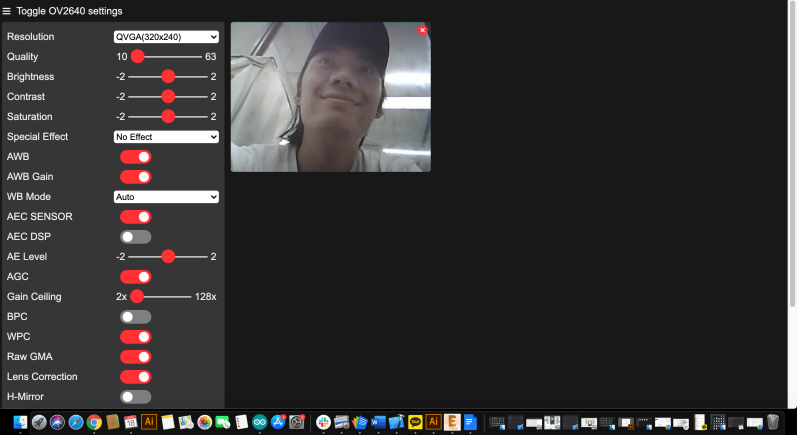

I could see that web and CAM were communicating through the serial monitor.
The end!
Use input devices : Link