Input Devices
This week, I learned how to measure and obtain input using a sensor. First, I tested the operating principles and processes of sensors with Aduino and made a board and moved it. There are three main types of sensors: digital sensors, analog sensors, and logic sensors. Each principle was explained in group work.
Here is our group works : week9
ESP32-CAM
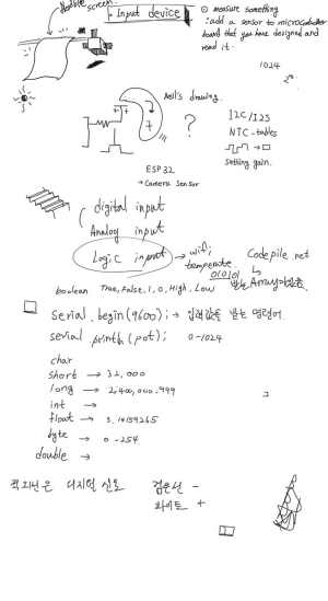
First of all, I will write down what I will do for the final project and what I wrote during the workshop.
I drew logic about the final project. It saves the video that Cam shows and makes it visible on the TFT Display, and allows it to stream different times for each display. So I designed and produced ESP32-CAM.
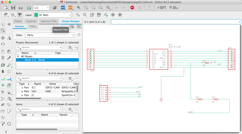
Schematic connects two 8pins and FTDIs in a structure that can be connected. The reason why each ESP32-CAM pin was connected to 8pin was to connect directly to the display so that it could be used.
Although a voltage divider was made on the FTDI connection of 6pin, 3.3V was not needed in advance with the built-in regulator. So I used a jumper to get 5V straight to the VCC pin.
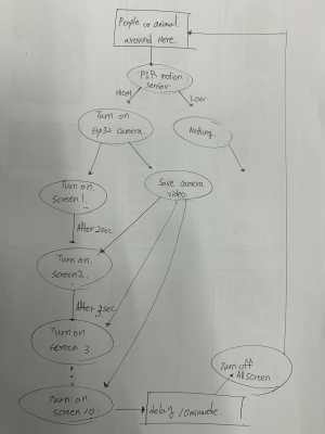
This is a sketch of my final project function. I will have PIR motion sensor turn on and use a storage and camera to allocate time for each screen.
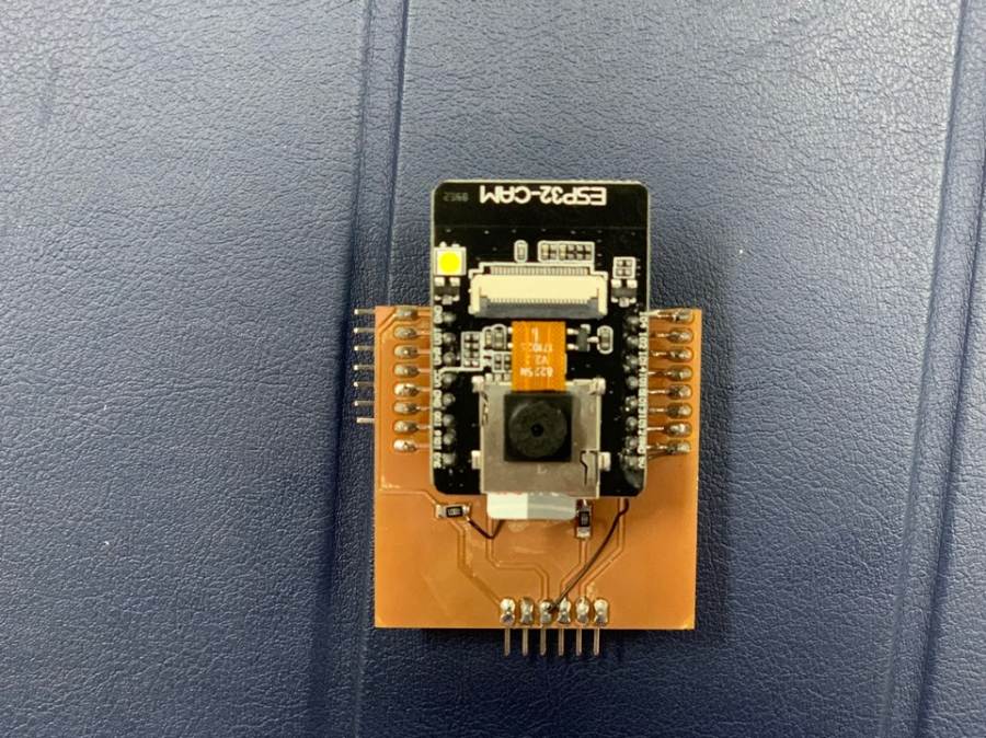
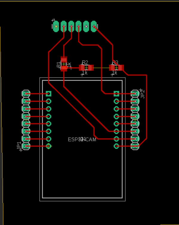
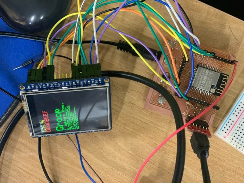
This is the ESP32-CAM board for this final project.
MCU with Wi-Fi connectivity, programming speed is a bit slow, but... I'm going to do a project that uses this board to stream time slowly.
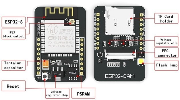
It refers to the structural features of ESP32-CAM. SD card can be used, Reset button is at the back, and Flash lamp also has. The lamp flashes when the reset button is pressed or the board is activated.
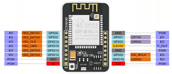
It is the pinout of esp32-CAM. There are three GND pins and two power pins (3.3V or 5V).
GPIO 1 and GPIO 3 are serial pins.
This pin is required to upload code to the board.
GPIO 0 also plays an important role because it determines whether ESP32 is in flash mode.
ESP32 flashes when GPIO 0 is connected to the GND.
The following pins are internally connected to the microSD card reader:
GPIO 14: CLK
GPIO 15: CMD
GPIO 2: Data 0
GPIO 4: Data 1 (also connected to the on-board LED)
GPIO 12: Data 2
GPIO 13: Data 3
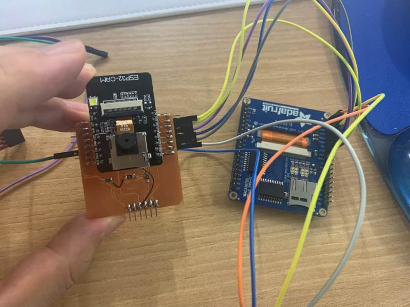
This is when ESP32-CAM is connected directly to the TFT display. The code below is a code that enables CAM streaming after direct connection.
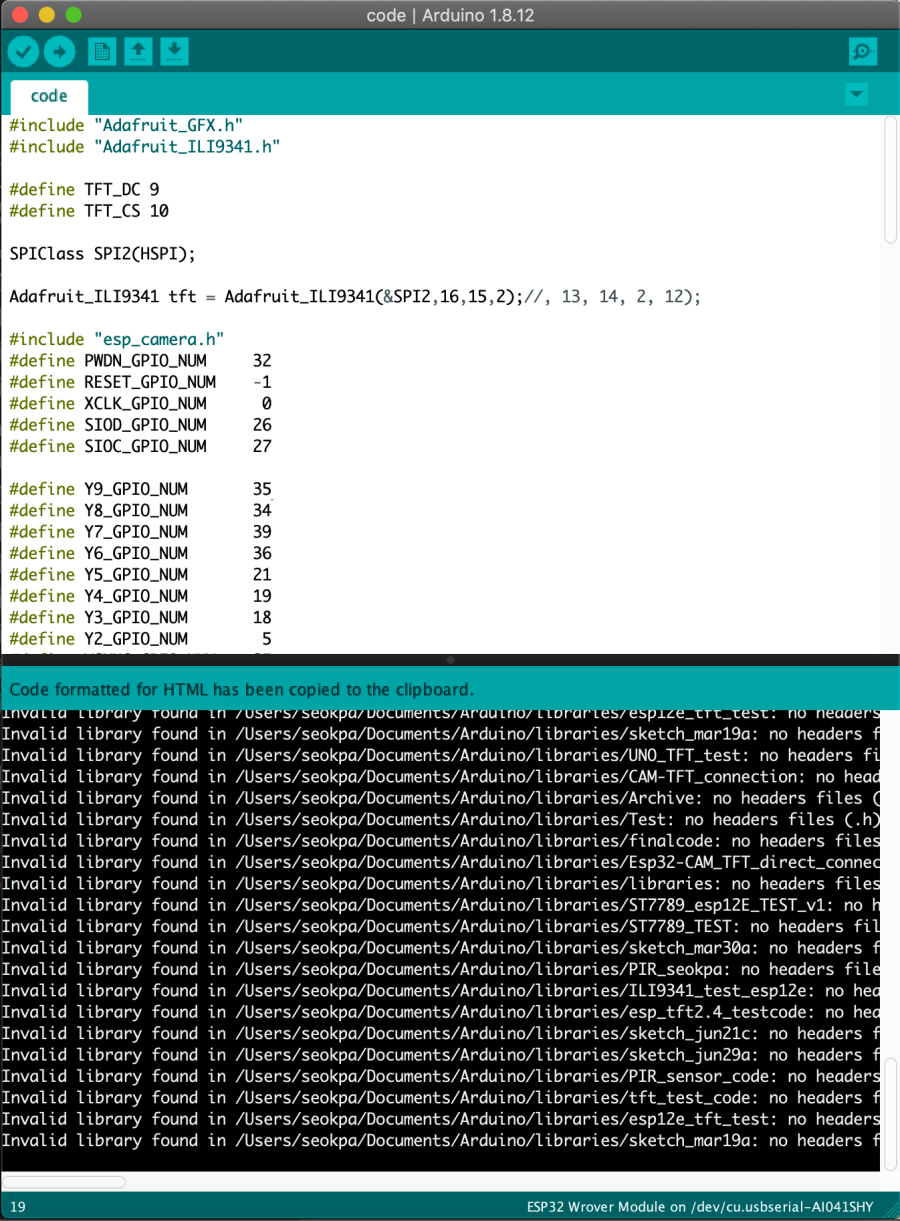
The upload is complete. But there is no response to the white screen.
TFT direct connect Code
#include "Adafruit_GFX.h"
#include "Adafruit_ILI9341.h"

#define TFT_DC 9
#define TFT_CS 10

SPIClass SPI2(HSPI);

Adafruit_ILI9341 tft = Adafruit_ILI9341(&SPI2,16,15,2);//, 13, 14, 2, 12);

#include "esp_camera.h"
#define PWDN_GPIO_NUM     32
#define RESET_GPIO_NUM    -1
#define XCLK_GPIO_NUM      0
#define SIOD_GPIO_NUM     26
#define SIOC_GPIO_NUM     27

#define Y9_GPIO_NUM       35
#define Y8_GPIO_NUM       34
#define Y7_GPIO_NUM       39
#define Y6_GPIO_NUM       36
#define Y5_GPIO_NUM       21
#define Y4_GPIO_NUM       19
#define Y3_GPIO_NUM       18
#define Y2_GPIO_NUM        5
#define VSYNC_GPIO_NUM    25
#define HREF_GPIO_NUM     23
#define PCLK_GPIO_NUM     22

void setup()
{
  Serial.begin(115200);
  Serial.setDebugOutput(true);
  Serial.println();

  Serial.println("ILI9341 Test!");
  tft.begin();
  tft.invertDisplay(false);
  // read diagnostics (optional but can help debug problems)
  tft.fillScreen(ILI9341_BLUE);

  camera_config_t config;
  config.ledc_channel = LEDC_CHANNEL_0;
  config.ledc_timer = LEDC_TIMER_0;
  config.pin_d0 = Y2_GPIO_NUM;
  config.pin_d1 = Y3_GPIO_NUM;
  config.pin_d2 = Y4_GPIO_NUM;
  config.pin_d3 = Y5_GPIO_NUM;
  config.pin_d4 = Y6_GPIO_NUM;
  config.pin_d5 = Y7_GPIO_NUM;
  config.pin_d6 = Y8_GPIO_NUM;
  config.pin_d7 = Y9_GPIO_NUM;
  config.pin_xclk = XCLK_GPIO_NUM;
  config.pin_pclk = PCLK_GPIO_NUM;
  config.pin_vsync = VSYNC_GPIO_NUM;
  config.pin_href = HREF_GPIO_NUM;
  config.pin_sscb_sda = SIOD_GPIO_NUM;
  config.pin_sscb_scl = SIOC_GPIO_NUM;
  config.pin_pwdn = PWDN_GPIO_NUM;
  config.pin_reset = RESET_GPIO_NUM;
  config.xclk_freq_hz = 20000000;
  config.pixel_format = PIXFORMAT_RGB565;
  //init with high specs to pre-allocate larger buffers
  {
    config.frame_size = FRAMESIZE_QQVGA;
    config.jpeg_quality = 12;
    config.fb_count = 1;
  }

  // camera init
  esp_err_t err = esp_camera_init(&config);
  if (err != ESP_OK)
  {
    Serial.printf("Camera init failed with error 0x%x", err);
    return;
  }
}

uint8_t buffer[38400];

void loop()
{
  camera_fb_t * fb = NULL;
  fb = esp_camera_fb_get();
  if (!fb)
  {
    Serial.println("Camera capture failed");
    return ;
  }
  Serial.print("WIDTH = ");
  Serial.print(fb->width);
  Serial.print("HEIGHT = ");
  Serial.print(fb->height);
  Serial.print("LENGTH = ");
  Serial.print(fb->len);
  Serial.println("");
  for( int i = 0; i < 19200; i++)
  {
    buffer[i*2] = fb->buf[i*2+1];
    buffer[i*2+1] = fb->buf[i*2];
  }
  tft.drawRGBBitmap(40,100,(uint16_t*)buffer, 160,120);

  esp_camera_fb_return(fb);
}
So as a solution, I decided to connect Wi-Fi and show it on the display. So I had to make another board. The process of making the board can be checked output week.
ESP32-CAM WIFI Streaming Code
#include "esp_camera.h"
#include <WiFi.h>
#include <ArduinoWebsockets.h>
//
// WARNING!!! Make sure that you have either selected ESP32 Wrover Module,
//            or another board which has PSRAM enabled
//

// Select camera model
//#define CAMERA_MODEL_WROVER_KIT
//#define CAMERA_MODEL_ESP_EYE
//#define CAMERA_MODEL_M5STACK_PSRAM
//#define CAMERA_MODEL_M5STACK_WIDE
#define CAMERA_MODEL_AI_THINKER

#include "camera_pins.h"

const char* ssid = "이노베이션팹랩_2G";
const char* password = "innovationpark";

const char* websockets_server_host = "192, 168, 1, 249";
const uint16_t websockets_server_port = 8888;

using namespace websockets;
WebsocketsClient client;

void setup() {
  Serial.begin(115200);
  Serial.setDebugOutput(true);
  Serial.println();

  camera_config_t config;
  config.ledc_channel = LEDC_CHANNEL_0;
  config.ledc_timer = LEDC_TIMER_0;
  config.pin_d0 = Y2_GPIO_NUM;
  config.pin_d1 = Y3_GPIO_NUM;
  config.pin_d2 = Y4_GPIO_NUM;
  config.pin_d3 = Y5_GPIO_NUM;
  config.pin_d4 = Y6_GPIO_NUM;
  config.pin_d5 = Y7_GPIO_NUM;
  config.pin_d6 = Y8_GPIO_NUM;
  config.pin_d7 = Y9_GPIO_NUM;
  config.pin_xclk = XCLK_GPIO_NUM;
  config.pin_pclk = PCLK_GPIO_NUM;
  config.pin_vsync = VSYNC_GPIO_NUM;
  config.pin_href = HREF_GPIO_NUM;
  config.pin_sscb_sda = SIOD_GPIO_NUM;
  config.pin_sscb_scl = SIOC_GPIO_NUM;
  config.pin_pwdn = PWDN_GPIO_NUM;
  config.pin_reset = RESET_GPIO_NUM;
  config.xclk_freq_hz = 10000000;
  config.pixel_format = PIXFORMAT_JPEG;
  //init with high specs to pre-allocate larger buffers
  if(psramFound()){
    config.frame_size = FRAMESIZE_QVGA; // 320x240
    config.jpeg_quality = 10;
    config.fb_count = 2;
  } else {
    config.frame_size = FRAMESIZE_SVGA;
    config.jpeg_quality = 12;
    config.fb_count = 1;
  }


  // camera init
  esp_err_t err = esp_camera_init(&config);
  if (err != ESP_OK) {
    Serial.printf("Camera init failed with error 0x%x", err);
    return;
  }


  WiFi.begin(ssid, password);

  while (WiFi.status() != WL_CONNECTED) {
    delay(500);
    Serial.print(".");
  }
  Serial.println("");
  Serial.println("WiFi connected");

  Serial.print("Camera Ready! Use 'http://");
  Serial.print(WiFi.localIP());
  Serial.println("' to connect");
 Serial.println("Connecting to screen:");
  while(!client.connect(websockets_server_host, websockets_server_port, "/")){
    delay(500);
    Serial.print(".");
  }

  Serial.println("Socket Connected!");
}

void loop() {
  camera_fb_t *fb = NULL;
  esp_err_t res = ESP_OK;
  fb = esp_camera_fb_get();
  if(!fb){
    Serial.println("Camera capture failed");
    esp_camera_fb_return(fb);
    return;
  }

  size_t fb_len = 0;
  if(fb->format != PIXFORMAT_JPEG){
    Serial.println("Non-JPEG data not implemented");
    return;
  }

  client.sendBinary((const char*) fb->buf, fb->len);
  esp_camera_fb_return(fb);
}
The parts I modified in the code are as follows.
config.frame_size = FRAMESIZE_SVGA;
config.jpeg_quality = 12;
configfb_count = 1;
In the setup window, you can adjust the size and quality, and the count can change the speed.
In loop(), a function defined as fb = esp_camera_fb_get(); was coded so that images received from the camera could be delivered to the TFT.
if(!fb){
Serial.println("Camera capture failed");
esp_camera_fb_return(fb);
return;
}
size_t fb_len = 0;
if(fb->format != PIXFORMAT_JPEG){
Serial.println("Non-JPEG data not implemented");
return;
} This code is coded to allow the camera to verify the success of the capture and then client.sendBinary ((host char*) fb->buf, fb->len);
esp_camera_fb_return(fb); code that passes through the code to the display.
Korean Reference : LINK
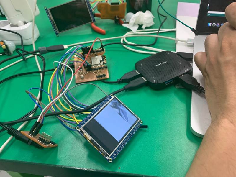
It's a little slow, but it can be streamed.
First, you can check the Wi-Fi connection between Input device and output device by going to the next link.
ESP32-CAM is important to keep streaming, so there should be no power issues.
Streaming while connecting to FTDI is not a good way.
It is better to have a definite power supply system.
And in order to use the camera, always disconnect GND and GPIO0, which were connected for upload.
WIFI connect with outputdevices : Link
esp32-cam.brd : Download
esp32-cam.sch : Download