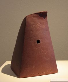
Concept sketch and reference
What does it do?
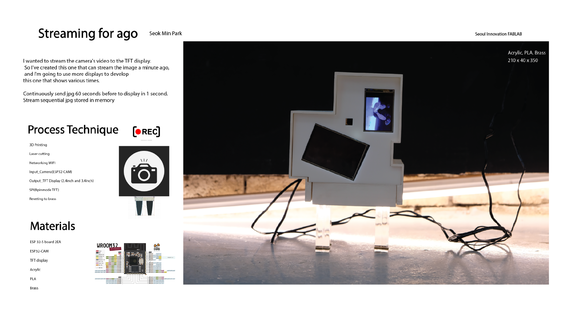
● This is an interactive piece that shows the world 60 seconds before the camera.
Who’s done what beforehand?
● I've seen a lot of different artists making works using displays or cameras. For example, I saw many expressions such as changing the angle of looking at the camera, what effects it might have on the display, and repeating itself. So I was inspired by it and tried to regenerate the past!
What did you design?
● First, I designed Esp32_cam chemical and ESP32_board. It was designed using Egle and used 8pin-mode TFT display. And I designed the main body with Fusion360, and I designed the middle part of the bridge.
What materials and components were used?
●The main body and center used PLA filaments, and the leg part used transparent acrylic. And we used 2.4 inch TFT and 3.2 inch TFT. And used brass sticks.
Where did they come from?
●PLA, ESP- MCU and acrylic were supported by Seoul Innovation FABLAB, brass, display and esp-CAM were purchased directly from the Korean site, Device Mart, and brass from the local store.
How much did they cost?
●It cost about 150,000 won in total. Two TFTs cost about 120,000 won, brass 10,000 won and camera 20,000 won.
What parts and systems were made?
●Continue to save the image on SD card in Esp32_cam. Then, ESP32_board sends images from 60 seconds ago sequentially to the TFT display. The faster the speed is, the faster the video can be streamed, but the ESP32 module is too much. So, it was best to send one image per second to make it work so that it didn't burn. Otherwise, I felt something burning on the ESP32-board.
What processes were used?
●The board was designed first, coded and tested, and produced the main body and other parts.
What questions were answered?
●t first, I thought streaming to the past would be impossible without using such things as ready-made Arduino or Raspberry Pie. However, I realized that it was relatively slow but possible with the system that I did now, so I felt that it could be developed in a different direction. For example, because you used Wi-Fi, you were less restricted by space, so you tried streaming a little farther away.
What worked? What didn’t?
●I tried streaming 120 seconds ago on the second TFT but it didn't work. So I'm solving the problem.
How was it evaluated?
●The initial design was to use more displays to express more time, but now it's a prototype. So while it is true that further development is needed, I am personally satisfied that the function has been successful!
What are the implications?
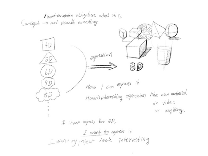
Concept 1
I want to make some sculpture what i'm not make ever.
I want to create an interactive art piece that shows various times at the same time!!
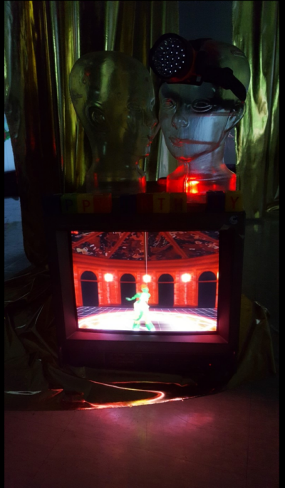
Concept2
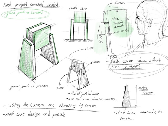
I thought of something I had never made with a final project. The technology that you want to apply is to show the video on the screen, although it is not yet exactly in shape. How does it look? It's a different time video from one camera to another on several screens. For example, the first screen is camera video 5 minutes ago, second is 1 minute ago, third is 30 seconds ago, etc. I want to express like this.
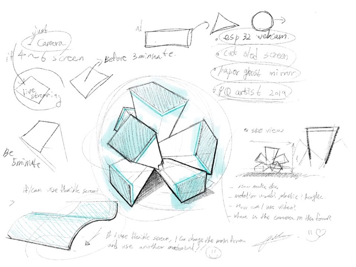
Concept3
well, If I use this form, i may use more sreen at my work.

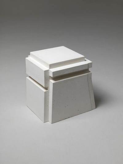

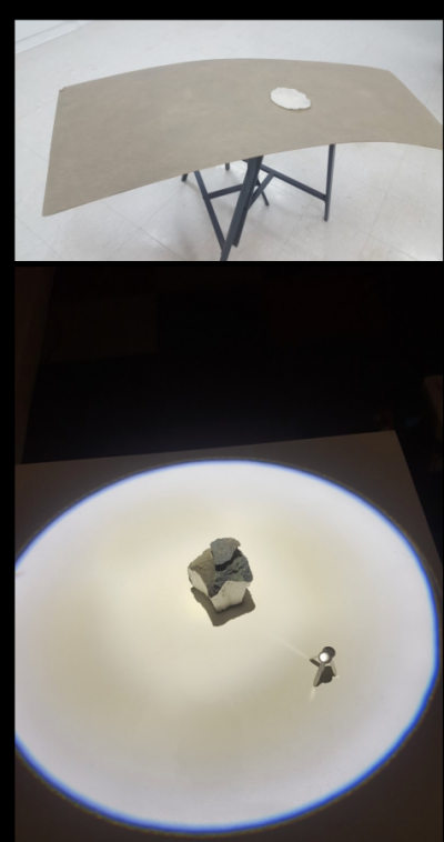
Similar sculptures were included in the detailed design for reference.
I tried to find references for the final project and apply them to the design.
I wanted to make the structure of the third sketch, but the interior space of the design form was small, so I had difficulty designing a space for the electronic board.
So I aimed to first succeed in delaying the time I wanted, then change the shape and use more displays.
Project Plan
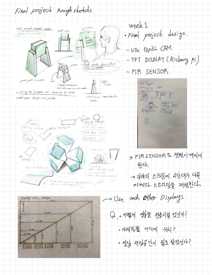
I had been thinking about how the ESSP32-CAM and TFT displays needed for the final project would network with each other and what sensors would be needed.
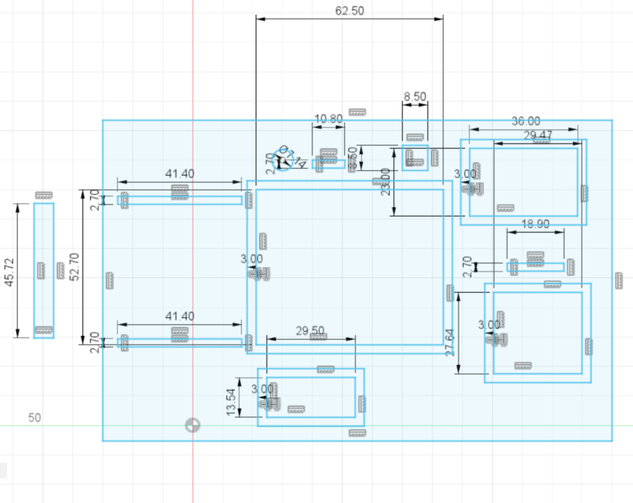
We then checked the size of each display to see what the actual size was.
To delay the camera's video, saving was essential, and I thought about how to send it.
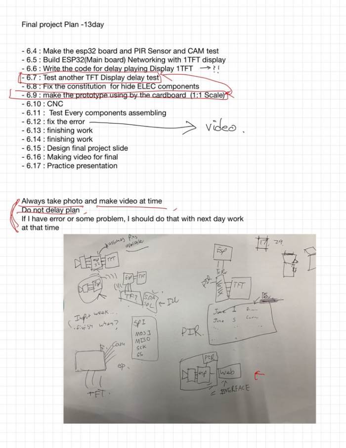
Then I checked the detailed work order from June 4th to the presentation day.
While drawing pictures, I checked the final project's system again.
And I tried to accurately identify and design the real and detailed size of the TFT display that I would use. The board I was going to use was going to be four boards. At first, I tried to use the ESP12e board, but I decided to use two ESP32-S boards because there were many 32 boards related to TFT display and 32 related to camera.

I thought about how to connect esp and display and how to work.
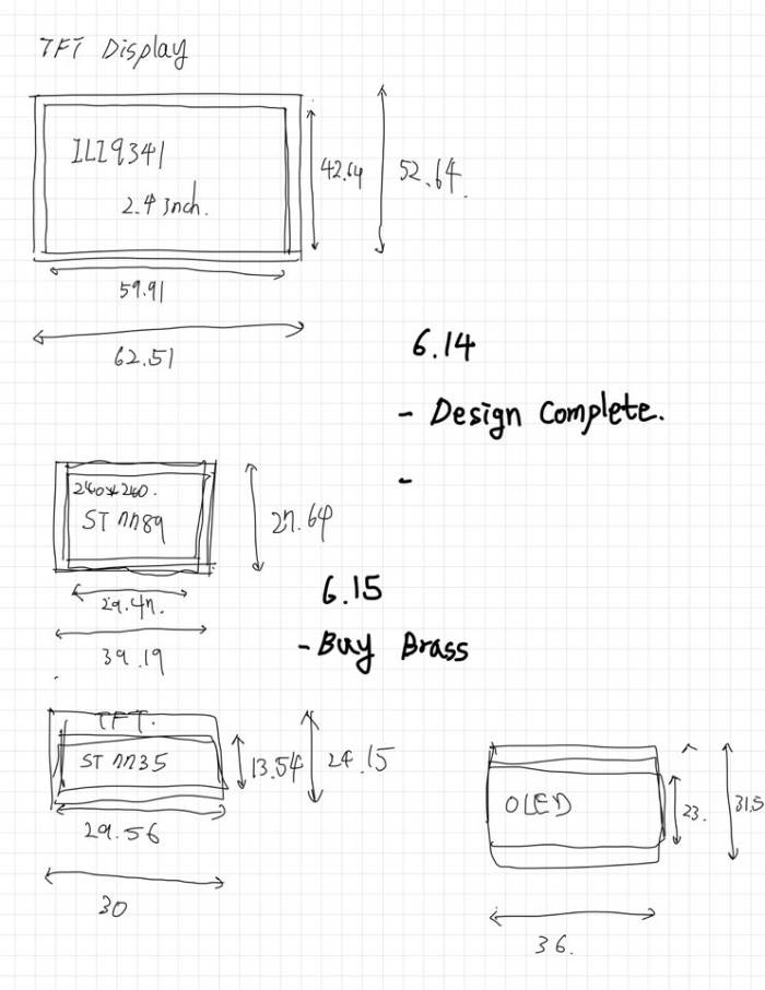
The actual size of each display was checked and designed.
Material Purchase and Preparation
The main materials for use are the plastic body made of 3D printing and the leg part using acrylic, and the main materials were riveted using brass. In case of TFT Display, it can be used with support from fab lab and purchase link is attached. I bought it from a Korean site.
BOM
● 2.4inch Adafruit TFT Display 1EA Link
● 3.5inch Adafruit TFT Display 1EA Link
● Brass reveting 3T 300mm offlinestore : 6,000₩
● Acrylic 10T from Fablab
● Esp32 components
| Part | Value | Device | Package | Description | CATEGORY | DESCRIPTION MANUFACTURER MF | MPN | OC_FARNELL OC_NEWARK OPERATING_TEMP PART_STATUS PROD_ID | RATING ROHS_COMPLIANT SERIES SUB-CATEGORY THERMALLOSS TOLERANCE TYPE VALUE |
|---|---|---|---|---|---|---|---|---|---|
| C1 | 100uf | C-USC1206 | C1206 | CAPACITOR, American symbol | |||||
| C2 | 10uf | C-USC1206 | C1206 | CAPACITOR, American symbol | |||||
| FLASH TAC_SWITCHSMD TAC_SWITCHSMD | TACTILE-SWITCH-SMD | Momentary Switch | SWCH-08247 | TAC_SWITCHSMD | |||||
| IC1 | LD1117 | LD1117 | SOT223 | 800mA and 1A Low Dropout (LDO) Positive Regulator | TEXAS INSTRUMENTS REG1117FAKTTT 1296120 | 87H2562 | |||
| J2 | 6_PIN_SERIAL_TARGETLONGPADS | 1X06_LONGPADS | 6-pin header connection for use with the "FTDI BASIC" pinout - TARGET SIDE. | ||||||
| J3 | DC-005 | CONN-POWER-JACK-2.1MM(DC-005) DCJ3P-14.2X11.0X9.0MM 320120003 | DC-005 | DC-005 | |||||
| JP1 | PINHD-1X14 | PINHD-1X14 | 1X14 | PIN HEADER | CONNECTOR | PIN-HEADER | |||
| JP2 | PINHD-1X14 | PINHD-1X14 | 1X14 | PIN HEADER | CONNECTOR | PIN-HEADER | |||
| JP3 | PINHD-1X10 | PINHD-1X10 | 1X10 | PIN HEADER | CONNECTOR | PIN-HEADER | |||
| R1 | 12K | R-US_CHIP-0805(2012-METRIC) | RESC2012X65 | Resistor Fixed - ANSI | Resistor | Fixed | |||
| R2 | 1K | R-US_MELF(3515-METRIC) | RESMELF3515 | Resistor Fixed - ANSI | Resistor | Fixed | |||
| R3 | 1K | R-US_MELF(3515-METRIC) | RESMELF3515 | Resistor Fixed - ANSI | Resistor | Fixed | |||
| R5 | 1k | R-US_MELF(3515-METRIC) | RESMELF3515 | Resistor Fixed - ANSI | Resistor | Fixed | |||
| R6 | 12K | R-US_CHIP-0805(2012-METRIC) | RESC2012X65 | Resistor Fixed - ANSI | Resistor | Fixed | |||
| RESET TAC_SWITCHSMD TAC_SWITCHSMD | TACTILE-SWITCH-SMD | Momentary Switch | SWCH-08247 | TAC_SWITCHSMD | |||||
| U1 | ESP-32S | ESP-32S | ESP-32S | Ai-Thinker ESP-32S |
The unit of money is WON(₩) in Korea.
Structure
Basically, my work, which is the size of the board, had to pay a lot of attention to size considerations.
The size of the display is limited, but in order to make the display's role more visible, it is designed to minimize the size of the display as much as possible and to hide the boards.
So I designed a right-angled structure, and the front part,
Laser cutting was used to reveal display and CAM.
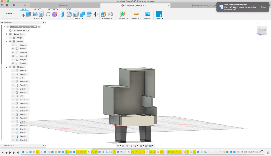
It's a design for the final project.
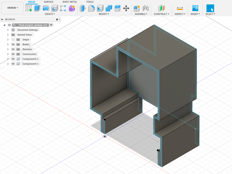
The body had to have all the electronic components and wires in it, so I designed it as above.
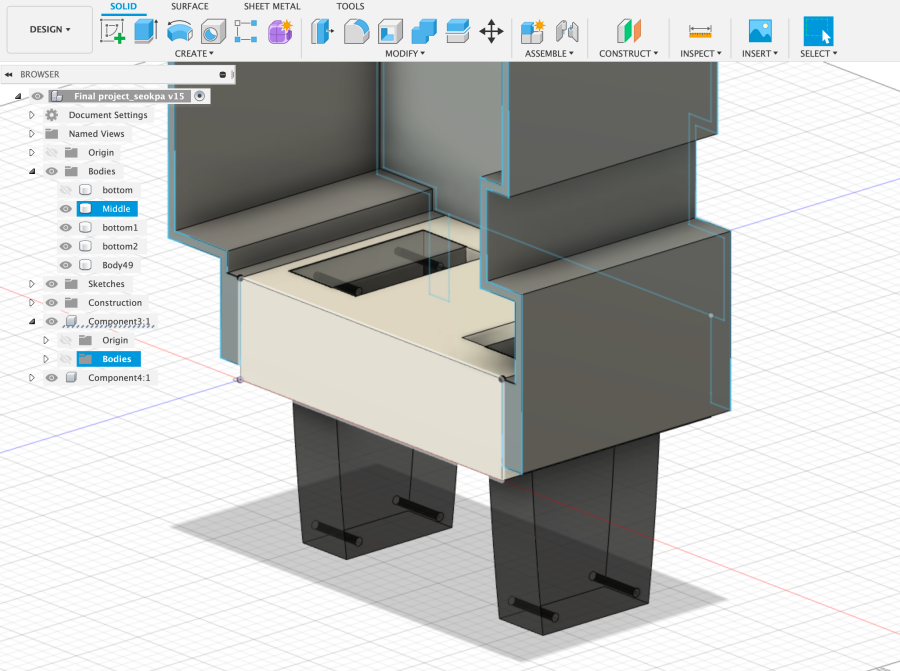
The main body, center, and leg parts will be riveted with brass rods.
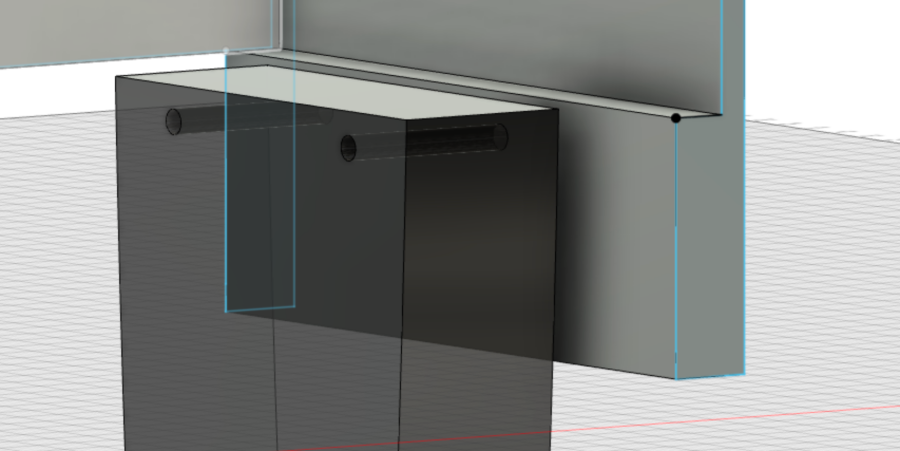
When enlarged, the 3mm brass rod is designed to be riveted.
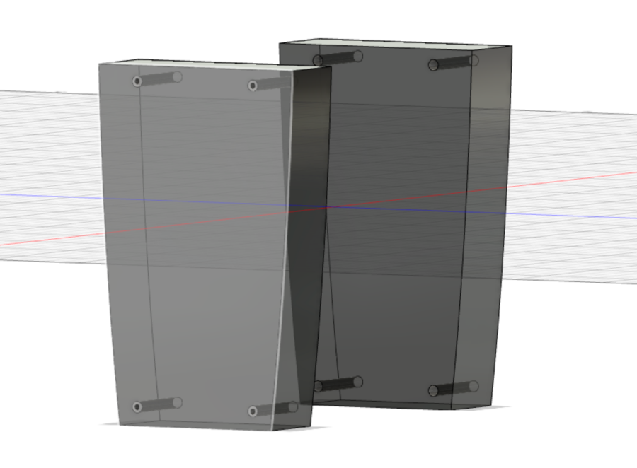
The leg part will use transparent acrylic.
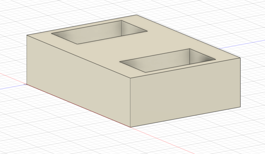
It's the middle part. It's a part that forgets the legs and the body.
Clearance was important in these designs. I thought I needed finishing as if I had a form.
The lower leg part is the part of the transparent acrylic 10T and the cover-like form is made of 3D printing.
The middle part was the part that allowed the cover and legs to be secured, and a structure that was assembled to fit the right size was needed.
So I repeated laser cutting and 3D printing for a perfect fit.
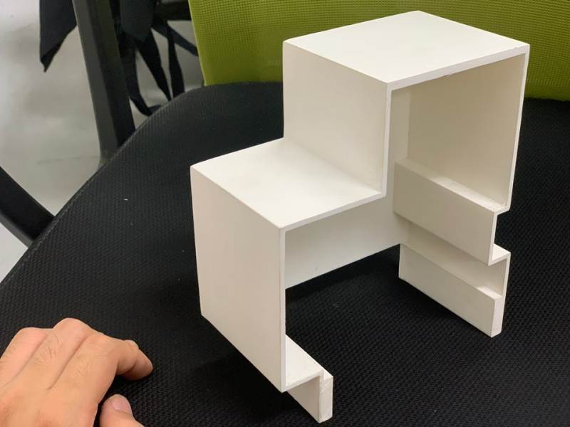
It was made with a 3D printer and did some finishing.
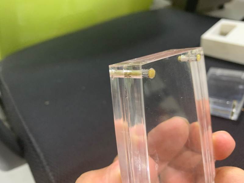
The acrylic leg was fixed with brass rod.
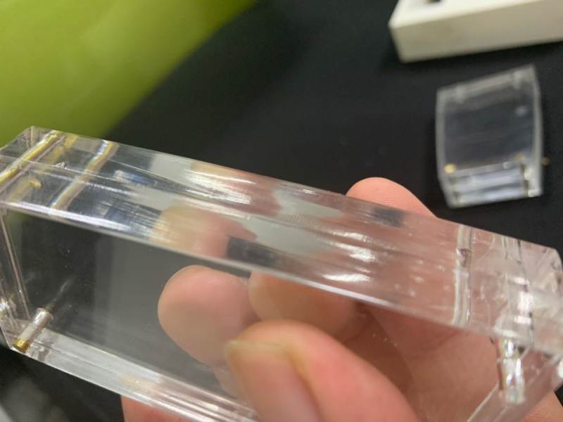
It is made to make the surface as clean as possible with laser cutter.
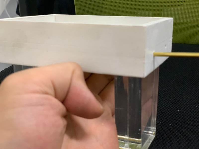
It connected the middle part and the leg part.
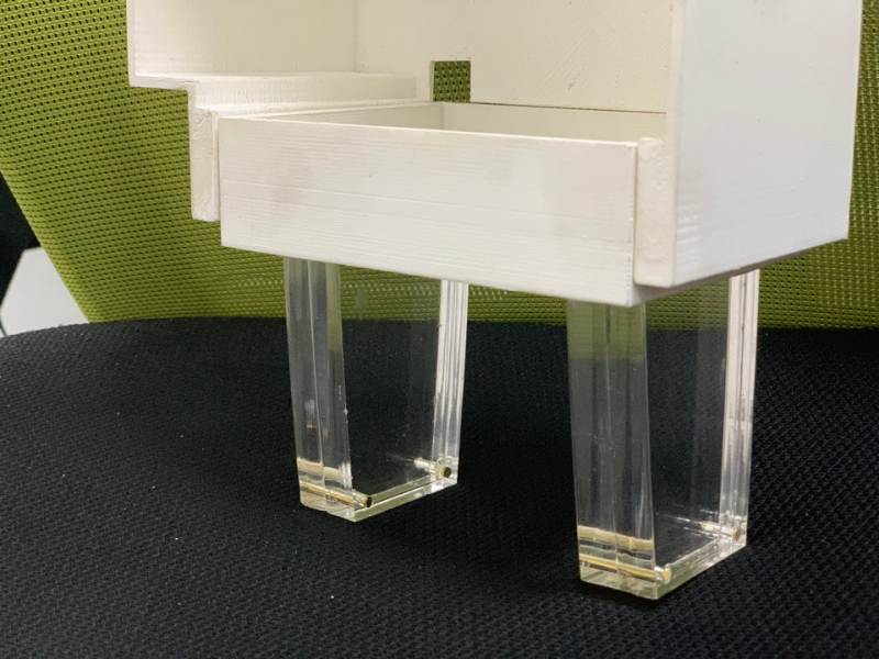
It's connected to the main body!
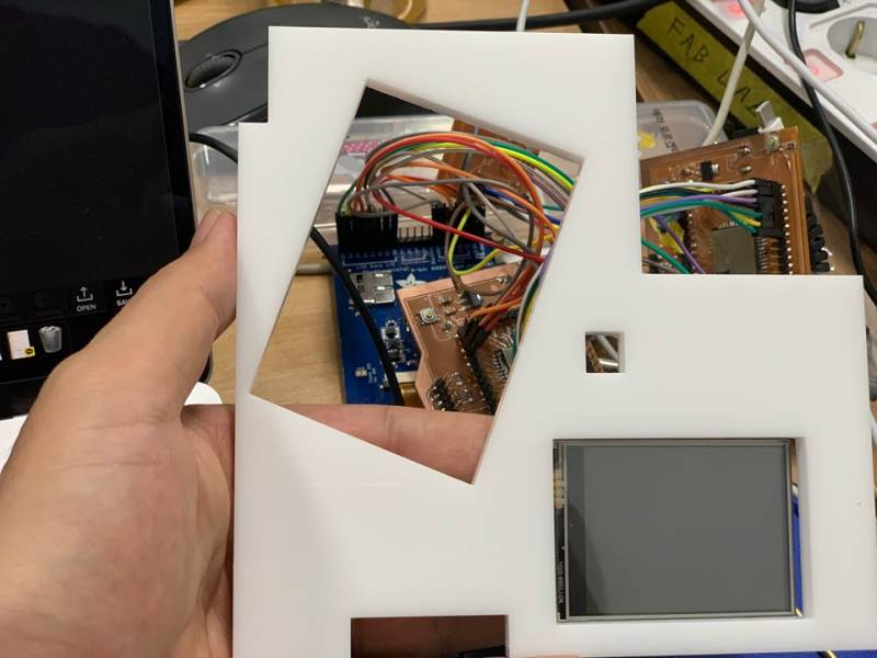
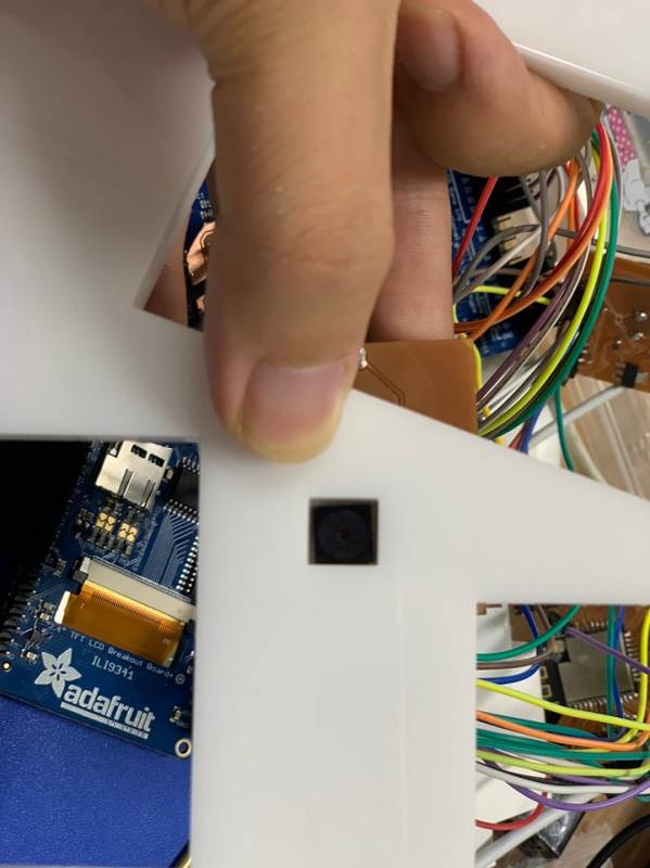
The front part was made to make each part look perfect. Clearance was given enough to hold the display and camera.
After 3D printing, layer was exposed, so putty was applied and finishing was done.
Then the butty hardened and sanded, and then primer and white color spray were used. And they used brass to fix acrylic and 3D printed work.
Transparent Acrylic used Trotec, which made several attempts to set the right value (power, speed) to cut off the surface. I tried setting power 100, speed 0.7 pp/Hz 20000
Electronic
I majored in metal craft and design, so I used to make something by hand.
However, it was the first time to make or program boards through fab academy.
So I had to study a lot, and there were many errors.
So I paid particular attention to this part and worked hard on it. I tried to understand, and I invested a lot of time.
Input Device
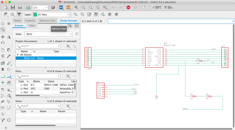
ESP-CAM schematic
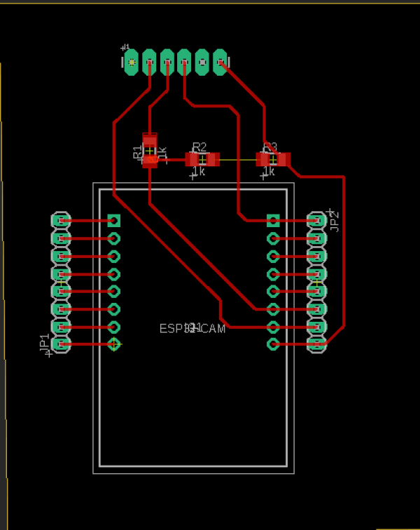
ESP-CAM Board design
The ESP32-CAM board serves to store videos on SD cards. The ESP32-CAM is Wi-Fi connected, and GPIO0 and GND must always be combined when programming.
And Arduino tool can be uploaded with ESP32-overmodule.
5V is required and, as with output week, the TX/RX has been converted to 3.3V.
output Device
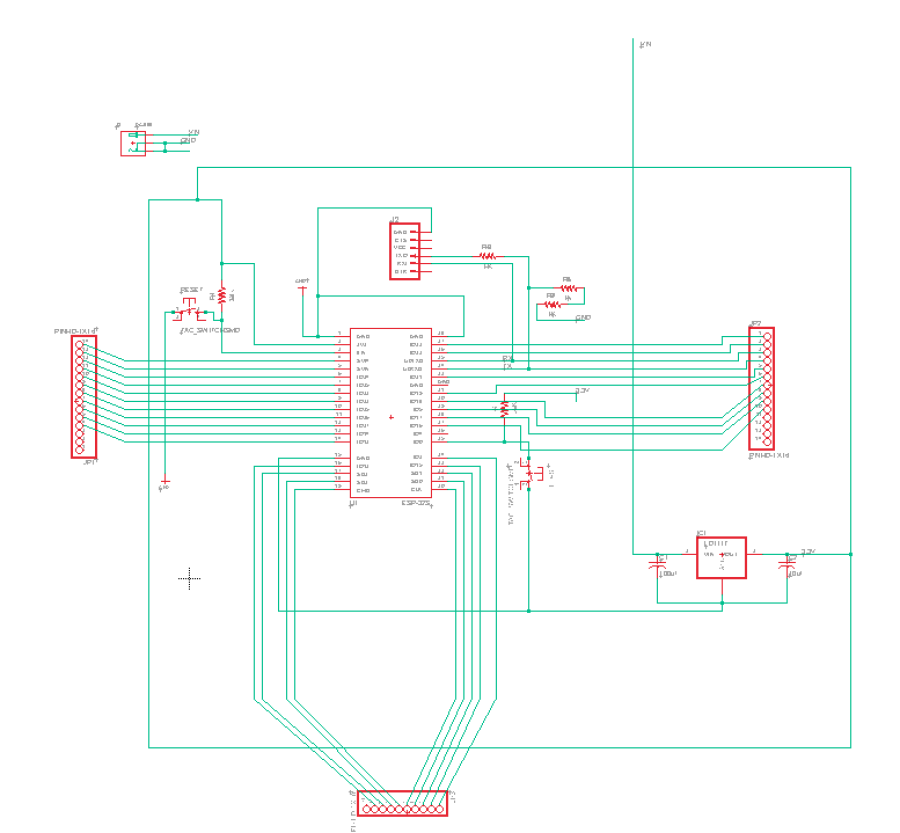
This is schematic
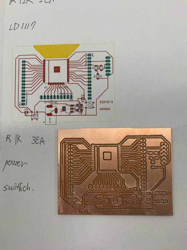
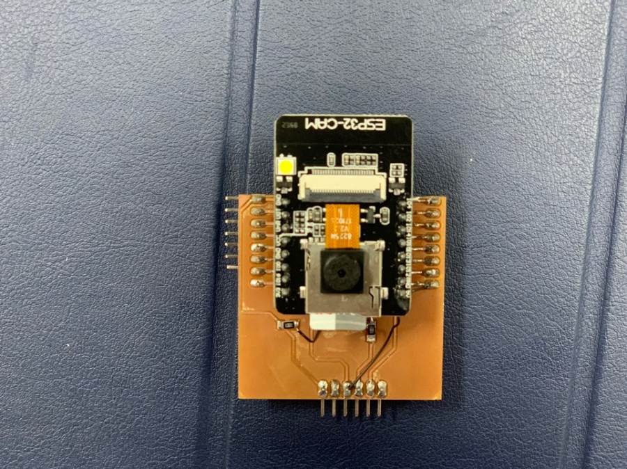
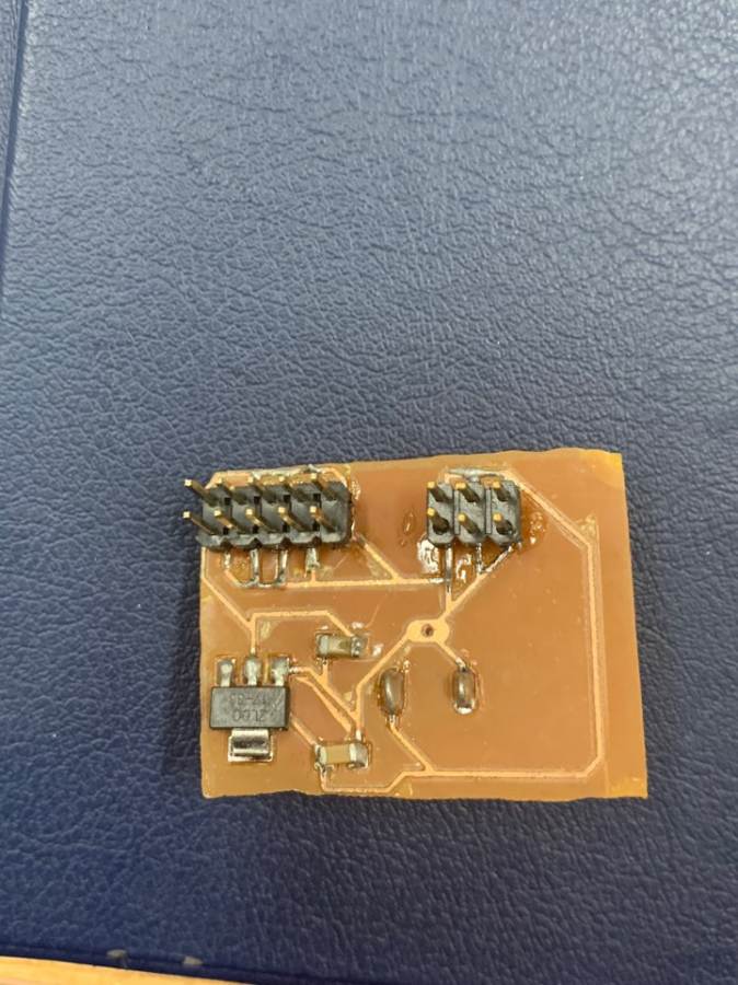
After milling for Bantam
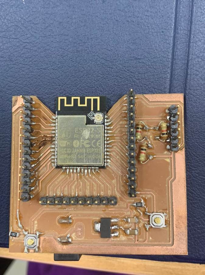
This is after soldering and checking the problem with a multimeter.
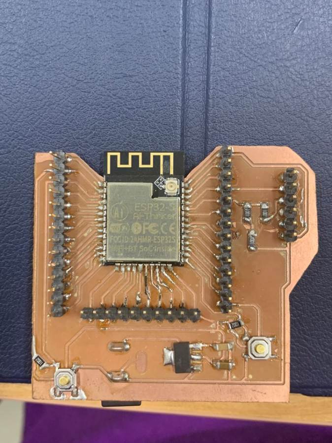
It is a development board using ESP32-S MCU.
The two boards are made of the same semantic.
The Arduino tool is an ESP32 Devmodule. Both boards are available when TFT uses SPI or 8-pinmode, and Wi-Fi is supported.
power supply board
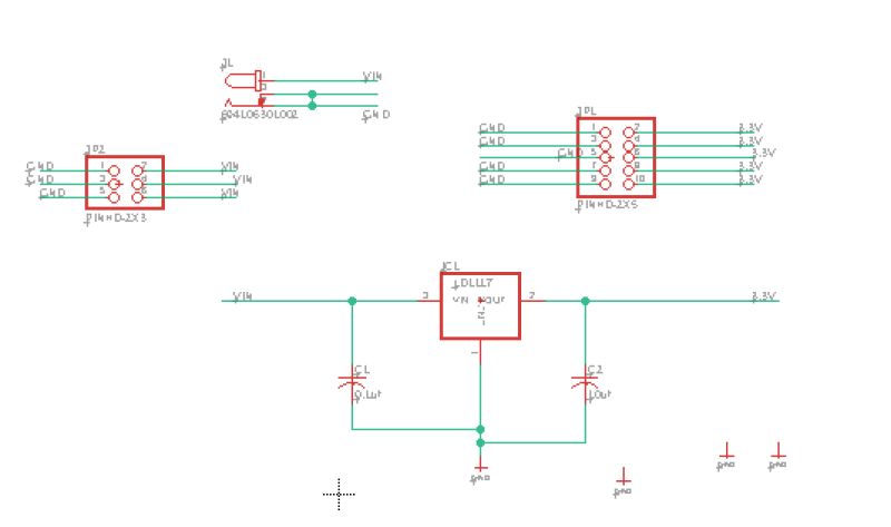
Power supply schematic
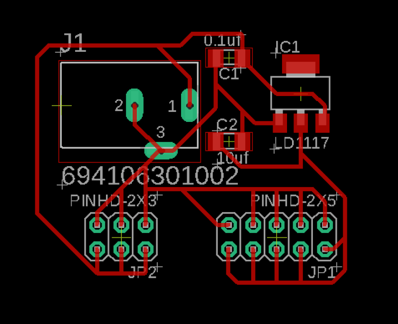
Board that can deliver both 3.3V and 5V is made separately. Because the voltage of the display and ESP is different.
The board was made into a power supply board capable of using 3.3V and 5V. For the two TFTs and CAMs, several jumpers were needed, and were designed to be supplied here. Con-Jack allowed 5V to be plugged in.
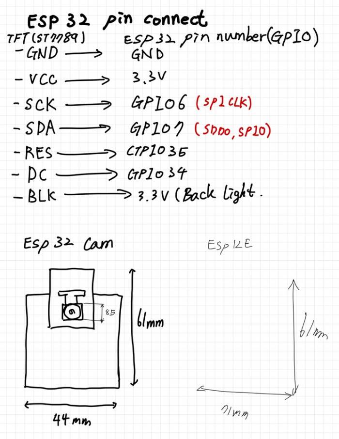
Wiring
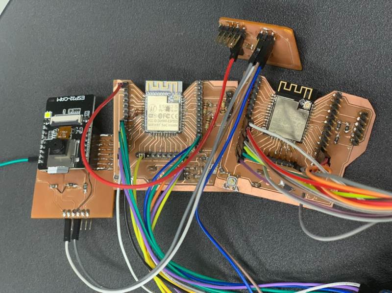
This is the connection of each component.
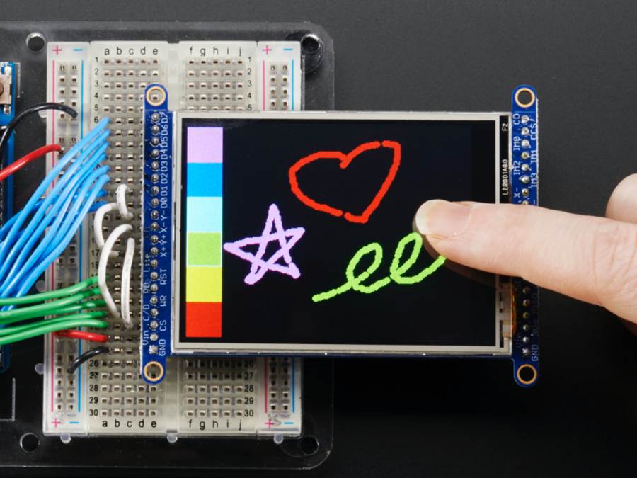
First of all, it is a display screen test code.
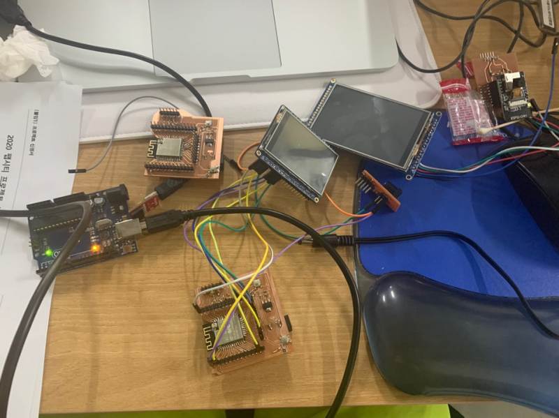
There are several important things in connecting devices.
Unfortunately, my TFT is not connected to SPI. Strangely, however, 8pin-mode was connected.
8pin mode can transmit data eight times faster than SPI.
If a line transmits 256 bits of data (SPI), 8-bit mode has eight lines.
If ESP32-CAM is directly connected to TFT, it will be possible to stream fast.
However, I will use WiFi so I don't think it will have a big impact.
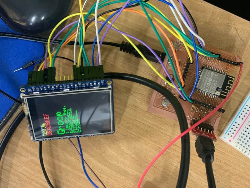
Here are the TFT test images and the last camera 60 seconds of delayed streaming.
The 60-second delay in streaming to Wi-Fi could not be attempted quickly.
The best level was to store one frame per second and read by TFT.
He tried to make it a frame per 0.5 second, but MCU got so hot that he couldn't stream the display smoothly.
So I decided to show the display one frame 60 seconds earlier.
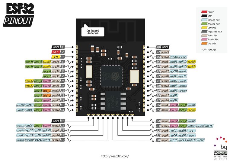
The code below is how to set up pins and libraries on TFT-espi. ESP32 has a variety of pins that can be connected to many SPIs and I2Cs. Several pins exist, such as VSPI and HSPI pin, but with speed differences. Connect the ESP32 board with the TFT to fit the pinout below.
//                            USER DEFINED SETTINGS
//   Set driver type, fonts to be loaded, pins used and SPI control method etc
//
//   See the User_Setup_Select.h file if you wish to be able to define multiple
//   setups and then easily select which setup file is used by the compiler.
//
//   If this file is edited correctly then all the library example sketches should
//   run without the need to make any more changes for a particular hardware setup!
//   Note that some sketches are designed for a particular TFT pixel width/height


// ##################################################################################
//
// Section 1. Call up the right driver file and any options for it
//
// ##################################################################################

// Define STM32 to invoke optimised processor support (only for STM32)
//#define STM32

// Defining the STM32 board allows the library to optimise the performance
// for UNO compatible "MCUfriend" style shields
//#define NUCLEO_64_TFT
//#define NUCLEO_144_TFT

// STM32 8 bit parallel only:
// If STN32 Port A or B pins 0-7 are used for 8 bit parallel data bus bits 0-7
// then this will improve rendering performance by a factor of ~8x
//#define STM_PORTA_DATA_BUS
//#define STM_PORTA_DATA_BUS

// Tell the library to use 8 bit parallel mode (otherwise SPI is assumed)
//#define TFT_PARALLEL_8_BIT

// Display type -  only define if RPi display
//#define RPI_DISPLAY_TYPE // 20MHz maximum SPI

// Only define one driver, the other ones must be commented out
#define ILI9341_DRIVER
//#define ST7735_DRIVER      // Define additional parameters below for this display
//#define ILI9163_DRIVER     // Define additional parameters below for this display
//#define S6D02A1_DRIVER
//#define RPI_ILI9486_DRIVER // 20MHz maximum SPI
//#define HX8357D_DRIVER
//#define ILI9481_DRIVER
//#define ILI9486_DRIVER
//#define ILI9488_DRIVER     // WARNING: Do not connect ILI9488 display SDO to MISO if other devices share the SPI bus (TFT SDO does NOT tristate when CS is high)
//#define ST7789_DRIVER      // Full configuration option, define additional parameters below for this display
//#define ST7789_2_DRIVER    // Minimal configuration option, define additional parameters below for this display
//#define R61581_DRIVER
//#define RM68140_DRIVER
//#define ST7796_DRIVER

// Some displays support SPI reads via the MISO pin, other displays have a single
// bi-directional SDA pin and the library will try to read this via the MOSI line.
// To use the SDA line for reading data from the TFT uncomment the following line:

// #define TFT_SDA_READ      // This option is for ESP32 ONLY, tested with ST7789 display only

// For ST7789 and ILI9341 ONLY, define the colour order IF the blue and red are swapped on your display
// Try ONE option at a time to find the correct colour order for your display

//  #define TFT_RGB_ORDER TFT_RGB  // Colour order Red-Green-Blue
//  #define TFT_RGB_ORDER TFT_BGR  // Colour order Blue-Green-Red

// For M5Stack ESP32 module with integrated ILI9341 display ONLY, remove // in line below

// #define M5STACK

// For ST7789, ST7735 and ILI9163 ONLY, define the pixel width and height in portrait orientation
// #define TFT_WIDTH  80
// #define TFT_WIDTH  128
// #define TFT_WIDTH  240 // ST7789 240 x 240 and 240 x 320
// #define TFT_HEIGHT 160
// #define TFT_HEIGHT 128
// #define TFT_HEIGHT 240 // ST7789 240 x 240
// #define TFT_HEIGHT 320 // ST7789 240 x 320

// For ST7735 ONLY, define the type of display, originally this was based on the
// colour of the tab on the screen protector film but this is not always true, so try
// out the different options below if the screen does not display graphics correctly,
// e.g. colours wrong, mirror images, or tray pixels at the edges.
// Comment out ALL BUT ONE of these options for a ST7735 display driver, save this
// this User_Setup file, then rebuild and upload the sketch to the board again:

// #define ST7735_INITB
// #define ST7735_GREENTAB
// #define ST7735_GREENTAB2
// #define ST7735_GREENTAB3
// #define ST7735_GREENTAB128    // For 128 x 128 display
// #define ST7735_GREENTAB160x80 // For 160 x 80 display (BGR, inverted, 26 offset)
// #define ST7735_REDTAB
// #define ST7735_BLACKTAB
// #define ST7735_REDTAB160x80   // For 160 x 80 display with 24 pixel offset

// If colours are inverted (white shows as black) then uncomment one of the next
// 2 lines try both options, one of the options should correct the inversion.

// #define TFT_INVERSION_ON
// #define TFT_INVERSION_OFF


// ##################################################################################
//
// Section 2. Define the pins that are used to interface with the display here
//
// ##################################################################################

// If a backlight control signal is available then define the TFT_BL pin in Section 2
// below. The backlight will be turned ON when tft.begin() is called, but the library
// needs to know if the LEDs are ON with the pin HIGH or LOW. If the LEDs are to be
// driven with a PWM signal or turned OFF/ON then this must be handled by the user
// sketch. e.g. with digitalWrite(TFT_BL, LOW);

// #define TFT_BL   32            // LED back-light control pin
// #define TFT_BACKLIGHT_ON HIGH  // Level to turn ON back-light (HIGH or LOW)


// We must use hardware SPI, a minimum of 3 GPIO pins is needed.
// Typical setup for ESP8266 NodeMCU ESP-12 is :
//
// Display SDO/MISO  to NodeMCU pin D6 (or leave disconnected if not reading TFT)
// Display LED       to NodeMCU pin VIN (or 5V, see below)
// Display SCK       to NodeMCU pin D5
// Display SDI/MOSI  to NodeMCU pin D7
// Display DC (RS/AO)to NodeMCU pin D3
// Display RESET     to NodeMCU pin D4 (or RST, see below)
// Display CS        to NodeMCU pin D8 (or GND, see below)
// Display GND       to NodeMCU pin GND (0V)
// Display VCC       to NodeMCU 5V or 3.3V
//
// The TFT RESET pin can be connected to the NodeMCU RST pin or 3.3V to free up a control pin
//
// The DC (Data Command) pin may be labeled AO or RS (Register Select)
//
// With some displays such as the ILI9341 the TFT CS pin can be connected to GND if no more
// SPI devices (e.g. an SD Card) are connected, in this case comment out the #define TFT_CS
// line below so it is NOT defined. Other displays such at the ST7735 require the TFT CS pin
// to be toggled during setup, so in these cases the TFT_CS line must be defined and connected.
//
// The NodeMCU D0 pin can be used for RST
//
//
// Note: only some versions of the NodeMCU provide the USB 5V on the VIN pin
// If 5V is not available at a pin you can use 3.3V but backlight brightness
// will be lower.


// ###### EDIT THE PIN NUMBERS IN THE LINES FOLLOWING TO SUIT YOUR ESP8266 SETUP ######

// For NodeMCU - use pin numbers in the form PIN_Dx where Dx is the NodeMCU pin designation
#define TFT_CS   PIN_D8  // Chip select control pin D8
#define TFT_DC   PIN_D3  // Data Command control pin
#define TFT_RST  PIN_D4  // Reset pin (could connect to NodeMCU RST, see next line)
//#define TFT_RST  -1    // Set TFT_RST to -1 if the display RESET is connected to NodeMCU RST or 3.3V

//#define TFT_BL PIN_D1  // LED back-light (only for ST7789 with backlight control pin)

//#define TOUCH_CS PIN_D2     // Chip select pin (T_CS) of touch screen

//#define TFT_WR PIN_D2       // Write strobe for modified Raspberry Pi TFT only


// ######  FOR ESP8266 OVERLAP MODE EDIT THE PIN NUMBERS IN THE FOLLOWING LINES  ######

// Overlap mode shares the ESP8266 FLASH SPI bus with the TFT so has a performance impact
// but saves pins for other functions. It is best not to connect MISO as some displays
// do not tristate that line wjen chip select is high!
// On NodeMCU 1.0 SD0=MISO, SD1=MOSI, CLK=SCLK to connect to TFT in overlap mode
// On NodeMCU V3  S0 =MISO, S1 =MOSI, S2 =SCLK
// In ESP8266 overlap mode the following must be defined

//#define TFT_SPI_OVERLAP

// In ESP8266 overlap mode the TFT chip select MUST connect to pin D3
//#define TFT_CS   PIN_D3
//#define TFT_DC   PIN_D5  // Data Command control pin
//#define TFT_RST  PIN_D4  // Reset pin (could connect to NodeMCU RST, see next line)
//#define TFT_RST  -1  // Set TFT_RST to -1 if the display RESET is connected to NodeMCU RST or 3.3V


// ###### EDIT THE PIN NUMBERS IN THE LINES FOLLOWING TO SUIT YOUR ESP32 SETUP   ######

// For ESP32 Dev board (only tested with ILI9341 display)
// The hardware SPI can be mapped to any pins

//#define TFT_MISO 19
//#define TFT_MOSI 23
//#define TFT_SCLK 18
//#define TFT_CS   15  // Chip select control pin
//#define TFT_DC    2  // Data Command control pin
//#define TFT_RST   4  // Reset pin (could connect to RST pin)
//#define TFT_RST  -1  // Set TFT_RST to -1 if display RESET is connected to ESP32 board RST

//#define TOUCH_CS 21     // Chip select pin (T_CS) of touch screen

//#define TFT_WR 22    // Write strobe for modified Raspberry Pi TFT only

// For the M5Stack module use these #define lines
//#define TFT_MISO 19
//#define TFT_MOSI 23
//#define TFT_SCLK 18
//#define TFT_CS   14  // Chip select control pin
//#define TFT_DC   27  // Data Command control pin
//#define TFT_RST  33  // Reset pin (could connect to Arduino RESET pin)
//#define TFT_BL   32  // LED back-light (required for M5Stack)

// ######       EDIT THE PINs BELOW TO SUIT YOUR ESP32 PARALLEL TFT SETUP        ######

// The library supports 8 bit parallel TFTs with the ESP32, the pin
// selection below is compatible with ESP32 boards in UNO format.
// Wemos D32 boards need to be modified, see diagram in Tools folder.
// Only ILI9481 and ILI9341 based displays have been tested!

// Parallel bus is only supported for the STM32 and ESP32
// Example below is for ESP32 Parallel interface with UNO displays

// Tell the library to use 8 bit parallel mode (otherwise SPI is assumed)
//#define TFT_PARALLEL_8_BIT

// The ESP32 and TFT the pins used for testing are:
#define TFT_CS   33  // Chip select control pin (library pulls permanently low
#define TFT_DC   15  // Data Command control pin - must use a pin in the range 0-31
#define TFT_RST  32  // Reset pin, toggles on startup

#define TFT_WR    4  // Write strobe control pin - must use a pin in the range 0-31
#define TFT_RD    2  // Read strobe control pin

#define TFT_D0   12  // Must use pins in the range 0-31 for the data bus
#define TFT_D1   13  // so a single register write sets/clears all bits.
#define TFT_D2   26  // Pins can be randomly assigned, this does not affect
#define TFT_D3   25  // TFT screen update performance.
#define TFT_D4   17
#define TFT_D5   16
#define TFT_D6   27
#define TFT_D7   14


// ##################################################################################
//
// Section 3. Define the fonts that are to be used here
//
// ##################################################################################

// Comment out the #defines below with // to stop that font being loaded
// The ESP8366 and ESP32 have plenty of memory so commenting out fonts is not
// normally necessary. If all fonts are loaded the extra FLASH space required is
// about 17Kbytes. To save FLASH space only enable the fonts you need!

#define LOAD_GLCD   // Font 1. Original Adafruit 8 pixel font needs ~1820 bytes in FLASH
#define LOAD_FONT2  // Font 2. Small 16 pixel high font, needs ~3534 bytes in FLASH, 96 characters
#define LOAD_FONT4  // Font 4. Medium 26 pixel high font, needs ~5848 bytes in FLASH, 96 characters
#define LOAD_FONT6  // Font 6. Large 48 pixel font, needs ~2666 bytes in FLASH, only characters 1234567890:-.apm
#define LOAD_FONT7  // Font 7. 7 segment 48 pixel font, needs ~2438 bytes in FLASH, only characters 1234567890:-.
#define LOAD_FONT8  // Font 8. Large 75 pixel font needs ~3256 bytes in FLASH, only characters 1234567890:-.
//#define LOAD_FONT8N // Font 8. Alternative to Font 8 above, slightly narrower, so 3 digits fit a 160 pixel TFT
#define LOAD_GFXFF  // FreeFonts. Include access to the 48 Adafruit_GFX free fonts FF1 to FF48 and custom fonts

// Comment out the #define below to stop the SPIFFS filing system and smooth font code being loaded
// this will save ~20kbytes of FLASH
#define SMOOTH_FONT


// ##################################################################################
//
// Section 4. Other options
//
// ##################################################################################

// Define the SPI clock frequency, this affects the graphics rendering speed. Too
// fast and the TFT driver will not keep up and display corruption appears.
// With an ILI9341 display 40MHz works OK, 80MHz sometimes fails
// With a ST7735 display more than 27MHz may not work (spurious pixels and lines)
// With an ILI9163 display 27 MHz works OK.

// #define SPI_FREQUENCY   1000000
// #define SPI_FREQUENCY   5000000
// #define SPI_FREQUENCY  10000000
// #define SPI_FREQUENCY  20000000
#define SPI_FREQUENCY  27000000 // Actually sets it to 26.67MHz = 80/3
// #define SPI_FREQUENCY  40000000
// #define SPI_FREQUENCY  80000000

// Optional reduced SPI frequency for reading TFT
#define SPI_READ_FREQUENCY  20000000

// The XPT2046 requires a lower SPI clock rate of 2.5MHz so we define that here:
#define SPI_TOUCH_FREQUENCY  2500000

// The ESP32 has 2 free SPI ports i.e. VSPI and HSPI, the VSPI is the default.
// If the VSPI port is in use and pins are not accessible (e.g. TTGO T-Beam)
// then uncomment the following line:
//#define USE_HSPI_PORT

// Comment out the following #define if "SPI Transactions" do not need to be
// supported. When commented out the code size will be smaller and sketches will
// run slightly faster, so leave it commented out unless you need it!

// Transaction support is needed to work with SD library but not needed with TFT_SdFat
// Transaction support is required if other SPI devices are connected.

// Transactions are automatically enabled by the library for an ESP32 (to use HAL mutex)
// so changing it here has no effect

// #define SUPPORT_TRANSACTIONS
ESP32-CAM Code
dea is a code used for ESP-CAM that allows real-time streaming to be shown to TFT display via Wi-Fi.
#include "esp_camera.h"
#include <WiFi.h>
#include <ArduinoWebsockets.h>
//
// WARNING!!! Make sure that you have either selected ESP32 Wrover Module,
//            or another board which has PSRAM enabled
//

// Select camera model
//#define CAMERA_MODEL_WROVER_KIT
//#define CAMERA_MODEL_ESP_EYE
//#define CAMERA_MODEL_M5STACK_PSRAM
//#define CAMERA_MODEL_M5STACK_WIDE
#define CAMERA_MODEL_AI_THINKER

#include "camera_pins.h"

const char* ssid = "이노베이션팹랩_2G";
const char* password = "innovationpark";

const char* websockets_server_host = "192, 168, 1, 249";
const uint16_t websockets_server_port = 8888;

using namespace websockets;
WebsocketsClient client;

void setup() {
  Serial.begin(115200);
  Serial.setDebugOutput(true);
  Serial.println();

  camera_config_t config;
  config.ledc_channel = LEDC_CHANNEL_0;
  config.ledc_timer = LEDC_TIMER_0;
  config.pin_d0 = Y2_GPIO_NUM;
  config.pin_d1 = Y3_GPIO_NUM;
  config.pin_d2 = Y4_GPIO_NUM;
  config.pin_d3 = Y5_GPIO_NUM;
  config.pin_d4 = Y6_GPIO_NUM;
  config.pin_d5 = Y7_GPIO_NUM;
  config.pin_d6 = Y8_GPIO_NUM;
  config.pin_d7 = Y9_GPIO_NUM;
  config.pin_xclk = XCLK_GPIO_NUM;
  config.pin_pclk = PCLK_GPIO_NUM;
  config.pin_vsync = VSYNC_GPIO_NUM;
  config.pin_href = HREF_GPIO_NUM;
  config.pin_sscb_sda = SIOD_GPIO_NUM;
  config.pin_sscb_scl = SIOC_GPIO_NUM;
  config.pin_pwdn = PWDN_GPIO_NUM;
  config.pin_reset = RESET_GPIO_NUM;
  config.xclk_freq_hz = 10000000;
  config.pixel_format = PIXFORMAT_JPEG;
  //init with high specs to pre-allocate larger buffers
  if(psramFound()){
    config.frame_size = FRAMESIZE_QVGA; // 320x240
    config.jpeg_quality = 10;
    config.fb_count = 2;
  } else {
    config.frame_size = FRAMESIZE_SVGA;
    config.jpeg_quality = 12;
    config.fb_count = 1;
  }


  // camera init
  esp_err_t err = esp_camera_init(&config);
  if (err != ESP_OK) {
    Serial.printf("Camera init failed with error 0x%x", err);
    return;
  }


  WiFi.begin(ssid, password);

  while (WiFi.status() != WL_CONNECTED) {
    delay(500);
    Serial.print(".");
  }
  Serial.println("");
  Serial.println("WiFi connected");

  Serial.print("Camera Ready! Use 'http://");
  Serial.print(WiFi.localIP());
  Serial.println("' to connect");
 Serial.println("Connecting to screen:");
  while(!client.connect(websockets_server_host, websockets_server_port, "/")){
    delay(500);
    Serial.print(".");
  }

  Serial.println("Socket Connected!");
}

void loop() {
  camera_fb_t *fb = NULL;
  esp_err_t res = ESP_OK;
  fb = esp_camera_fb_get();
  if(!fb){
    Serial.println("Camera capture failed");
    esp_camera_fb_return(fb);
    return;
  }

  size_t fb_len = 0;
  if(fb->format != PIXFORMAT_JPEG){
    Serial.println("Non-JPEG data not implemented");
    return;
  }

  client.sendBinary((const char*) fb->buf, fb->len);
  esp_camera_fb_return(fb);
}
ESP32-Board WIFI Streaming Code
This code is a code that receives images sent by ESP-32 Board from ESP32-CAM via Wi-Fi and shows them in real time.That is, the code that allows the TFT to receive images of the camera.
#include <SPIFFS.h>
#include <SPI.h>
#include <Adafruit_GFX.h>
#include <Adafruit_ILI9341.h>

#include <ArduinoWebsockets.h>
#include <WiFi.h>

#include <JPEGDecoder.h>

#define TFT_DC 17
#define TFT_CS 5
#define TFT_RST 4

const char* ssid = "이노베이션팹랩_2G";
const char* password = "innovationpark";
const char* imageFileName = "/camimage.jpeg";

using namespace websockets;
WebsocketsServer server;
WebsocketsClient client;

Adafruit_ILI9341 tft = Adafruit_ILI9341(TFT_CS, TFT_DC, TFT_RST);
boolean SDInited = false;

void setup() {
  // put your setup code here, to run once:
  Serial.begin(115200);
  delay(1000);

  tft.begin();
  tft.setRotation(3);
  tft.fillScreen(ILI9341_RED);

  if(!SPIFFS.begin(true)){
    Serial.println("SPIFFS init failed!");
    while(1) yield();
  }else{
    SDInited = true;
  }


  WiFi.begin(ssid, password);

  while (WiFi.status() != WL_CONNECTED) {
    delay(500);
    Serial.print(".");
  }
  Serial.println("");
  Serial.println("WiFi connected");


  WiFi.begin(ssid, password);

  while (WiFi.status() != WL_CONNECTED) {
    delay(500);
    Serial.print(".");
  }
  Serial.println("");
  Serial.println("WiFi connected");

  Serial.print(WiFi.localIP());

  server.listen(8888);
}

void loop() {
  // put your main code here, to run repeatedly:
  if(SDInited){
    if(server.poll()){
      client = server.accept();
    }

    if(client.available()){
      client.poll();

      WebsocketsMessage msg = client.readBlocking();
      boolean isSaved = fileWrite(imageFileName, msg);
      if(isSaved){
        drawJpeg(imageFileName, 0, 0 );
      }
    }
  }
}

boolean fileWrite(String name, WebsocketsMessage content){
  File file = SPIFFS.open(name.c_str(), "w");
  if(!file){
    String errorMsg = "Can't open file";
    Serial.println(errorMsg);
    return false;
  }else{
    file.write((const uint8_t*) content.c_str(), content.length());
    file.close();
    return true;
  }
}

/*====================================================================================
  This sketch contains support functions to render the Jpeg images.

  Created by Bodmer 15th Jan 2017
  ==================================================================================*/

// Return the minimum of two values a and b
#define minimum(a,b)     (((a) < (b)) ? (a) : (b))

//====================================================================================
//   Opens the image file and prime the Jpeg decoder
//====================================================================================
void drawJpeg(const char *filename, int xpos, int ypos) {

  Serial.println("===========================");
  Serial.print("Drawing file: "); Serial.println(filename);
  Serial.println("===========================");

  // Open the named file (the Jpeg decoder library will close it after rendering image)
  fs::File jpegFile = SPIFFS.open( filename, "r");    // File handle reference for SPIFFS
  //  File jpegFile = SD.open( filename, FILE_READ);  // or, file handle reference for SD library

  if ( !jpegFile ) {
    Serial.print("ERROR: File \""); Serial.print(filename); Serial.println ("\" not found!");
    return;
  }

  // Use one of the three following methods to initialise the decoder:
  //boolean decoded = JpegDec.decodeFsFile(jpegFile); // Pass a SPIFFS file handle to the decoder,
  //boolean decoded = JpegDec.decodeSdFile(jpegFile); // or pass the SD file handle to the decoder,
  boolean decoded = JpegDec.decodeFsFile(filename);  // or pass the filename (leading / distinguishes SPIFFS files)
                                   // Note: the filename can be a String or character array type
  if (decoded) {
    // print information about the image to the serial port
    jpegInfo();

    // render the image onto the screen at given coordinates
    jpegRender(xpos, ypos);
  }
  else {
    Serial.println("Jpeg file format not supported!");
  }
}

//====================================================================================
//   Decode and render the Jpeg image onto the TFT screen
//====================================================================================
void jpegRender(int xpos, int ypos) {

  // retrieve infomration about the image
  uint16_t  *pImg;
  uint16_t mcu_w = JpegDec.MCUWidth;
  uint16_t mcu_h = JpegDec.MCUHeight;
  uint32_t max_x = JpegDec.width;
  uint32_t max_y = JpegDec.height;

  // Jpeg images are draw as a set of image block (tiles) called Minimum Coding Units (MCUs)
  // Typically these MCUs are 16x16 pixel blocks
  // Determine the width and height of the right and bottom edge image blocks
  uint32_t min_w = minimum(mcu_w, max_x % mcu_w);
  uint32_t min_h = minimum(mcu_h, max_y % mcu_h);

  // save the current image block size
  uint32_t win_w = mcu_w;
  uint32_t win_h = mcu_h;

  // record the current time so we can measure how long it takes to draw an image
  uint32_t drawTime = millis();

  // save the coordinate of the right and bottom edges to assist image cropping
  // to the screen size
  max_x += xpos;
  max_y += ypos;

  // read each MCU block until there are no more
  while ( JpegDec.read()) {

    // save a pointer to the image block
    pImg = JpegDec.pImage;

    // calculate where the image block should be drawn on the screen
    int mcu_x = JpegDec.MCUx * mcu_w + xpos;
    int mcu_y = JpegDec.MCUy * mcu_h + ypos;

    // check if the image block size needs to be changed for the right edge
    if (mcu_x + mcu_w <= max_x) win_w = mcu_w;
    else win_w = min_w;

    // check if the image block size needs to be changed for the bottom edge
    if (mcu_y + mcu_h <= max_y) win_h = mcu_h;
    else win_h = min_h;

    // copy pixels into a contiguous block
    if (win_w != mcu_w)
    {
      for (int h = 1; h < win_h-1; h++)
      {
        memcpy(pImg + h * win_w, pImg + (h + 1) * mcu_w, win_w << 1);
      }
    }

    // draw image MCU block only if it will fit on the screen
    if ( ( mcu_x + win_w) <= tft.width() && ( mcu_y + win_h) <= tft.height())
    {
      tft.drawRGBBitmap(mcu_x, mcu_y, pImg, win_w, win_h);
    }

    else if ( ( mcu_y + win_h) >= tft.height()) JpegDec.abort();

  }

  // calculate how long it took to draw the image
  drawTime = millis() - drawTime; // Calculate the time it took

  // print the results to the serial port
  Serial.print  ("Total render time was    : "); Serial.print(drawTime); Serial.println(" ms");
  Serial.println("=====================================");

}

//====================================================================================
//   Print information decoded from the Jpeg image
//====================================================================================
void jpegInfo() {

  Serial.println("===============");
  Serial.println("JPEG image info");
  Serial.println("===============");
  Serial.print  ("Width      :"); Serial.println(JpegDec.width);
  Serial.print  ("Height     :"); Serial.println(JpegDec.height);
  Serial.print  ("Components :"); Serial.println(JpegDec.comps);
  Serial.print  ("MCU / row  :"); Serial.println(JpegDec.MCUSPerRow);
  Serial.print  ("MCU / col  :"); Serial.println(JpegDec.MCUSPerCol);
  Serial.print  ("Scan type  :"); Serial.println(JpegDec.scanType);
  Serial.print  ("MCU width  :"); Serial.println(JpegDec.MCUWidth);
  Serial.print  ("MCU height :"); Serial.println(JpegDec.MCUHeight);
  Serial.println("===============");
  Serial.println("");
}

//====================================================================================
//   Open a Jpeg file and send it to the Serial port in a C array compatible format
//====================================================================================
void createArray(const char *filename) {

  // Open the named file
  fs::File jpgFile = SPIFFS.open( filename, "r");    // File handle reference for SPIFFS
  //  File jpgFile = SD.open( filename, FILE_READ);  // or, file handle reference for SD library

  if ( !jpgFile ) {
    Serial.print("ERROR: File \""); Serial.print(filename); Serial.println ("\" not found!");
    return;
  }

  uint8_t data;
  byte line_len = 0;
  Serial.println("");
  Serial.println("// Generated by a JPEGDecoder library example sketch:");
  Serial.println("// https://github.com/Bodmer/JPEGDecoder");
  Serial.println("");
  Serial.println("#if defined(__AVR__)");
  Serial.println("  #include <avr/pgmspace.h>");
  Serial.println("#endif");
  Serial.println("");
  Serial.print  ("const uint8_t ");
  while (*filename != '.') Serial.print(*filename++);
  Serial.println("[] PROGMEM = {"); // PROGMEM added for AVR processors, it is ignored by Due

  while ( jpgFile.available()) {

    data = jpgFile.read();
    Serial.print("0x"); if (abs(data) < 16) Serial.print("0");
    Serial.print(data, HEX); Serial.print(",");// Add value and comma
    line_len++;
    if ( line_len >= 32) {
      line_len = 0;
      Serial.println();
    }

  }

  Serial.println("};\r\n");
  jpgFile.close();
}
//====================================================================================
ESP32-Board WIFI Streaming code v2
This code, as above, plays the same role. It is a code that receives images of a camera in real time and sends them to TFT.
However, the difference is that it uses the Espi_TFT Library. Using this library, you can set the display size and type according to the type of TFT, and use the library to make it available not only in ESP32 but also in ESP8266.
#include <SPIFFS.h>
#include <SPI.h>

#include <ArduinoWebsockets.h>
#include <WiFi.h>

#include <TJpg_Decoder.h>
#include <TFT_eSPI.h>

const char* ssid = "이노베이션팹랩_2G";
const char* password = "innovationpark";
const char* imageFileName = "/camimage.jpeg";

IPAddress local_IP(192, 168, 1, 249);
IPAddress gateway(192, 168, 1, 1);
IPAddress subnet(255, 255, 255, 0);
IPAddress primaryDNS(8, 8, 8, 8); //optional
IPAddress secondaryDNS(8, 8, 4, 4); //optional


using namespace websockets;
WebsocketsServer server;
WebsocketsClient client;

TFT_eSPI tft = TFT_eSPI();         // Invoke custom library
boolean SDInited = false;

bool tft_output(int16_t x, int16_t y, uint16_t w, uint16_t h, uint16_t* bitmap)
{
   // Stop further decoding as image is running off bottom of screen
  if ( y >= tft.height() ) return 0;

  // This function will clip the image block rendering automatically at the TFT boundaries
  tft.pushImage(x, y, w, h, bitmap);

  // This might work instead if you adapt the sketch to use the Adafruit_GFX library
  // tft.drawRGBBitmap(x, y, bitmap, w, h);

  // Return 1 to decode next block
  return 1;
}


void setup() {
  // put your setup code here, to run once:
  Serial.begin(115200);
  delay(1000);

  if(!SPIFFS.begin(true)){
    Serial.println("SPIFFS init failed!");
    while(1) yield();
  }else{
    SDInited = true;
  }

  tft.begin();
  tft.setRotation(3);
  tft.setTextColor(0xFFFF, 0x0000);
  tft.fillScreen(TFT_RED);
  tft.setSwapBytes(true); // We need to swap the colour bytes (endianess)

  // The jpeg image can be scaled by a factor of 1, 2, 4, or 8
  TJpgDec.setJpgScale(1);

  // The decoder must be given the exact name of the rendering function above
  TJpgDec.setCallback(tft_output);

  Serial.println();
  Serial.println("Setting AP...");


if (!WiFi.config(local_IP, gateway, subnet, primaryDNS, secondaryDNS)) {
    Serial.println("STA Failed to configure");
  }


  WiFi.begin(ssid, password);


while (WiFi.status() != WL_CONNECTED) {
    delay(500);
    Serial.print(".");
  }


 Serial.println("");
 Serial.println("WiFi connected");
 Serial.print(WiFi.localIP());

  server.listen(8888);
}

void loop() {
  // put your main code here, to run repeatedly:
  if(SDInited){
    if(server.poll()){
      client = server.accept();
    }

    if(client.available()){
      client.poll();

      WebsocketsMessage msg = client.readBlocking();
      boolean isSaved = fileWrite(imageFileName, msg);
      if(isSaved){

        uint32_t t = millis();

        // Get the width and height in pixels of the jpeg if you wish
        uint16_t w = 0, h = 0;
        TJpgDec.getFsJpgSize(&w, &h, imageFileName); // Note name preceded with "/"
        Serial.print("Width = "); Serial.print(w); Serial.print(", height = "); Serial.println(h);

        // Draw the image, top left at 0,0
        TJpgDec.drawFsJpg(0, 0, imageFileName);

        // How much time did rendering take (ESP8266 80MHz 271ms, 160MHz 157ms, ESP32 SPI 120ms, 8bit parallel 105ms
        t = millis() - t;
        Serial.print(t); Serial.println(" ms");
      }
    }
  }
}

boolean fileWrite(String name, WebsocketsMessage content){
  File file = SPIFFS.open(name.c_str(), "w");
  if(!file){
    String errorMsg = "Can't open file";
    Serial.println(errorMsg);
    return false;
  }else{
    file.write((const uint8_t*) content.c_str(), content.length());
    file.close();
    return true;
  }
}
ESP32-CAM WIFI Streaming 60sec delay code(by saving SDCARD)
This code puts SD storage into the ESP32-CAM and transmits the image that the camera saw 60 seconds ago to the ESP32-Board. It is a code that continuously sends images 60 seconds or 1 minute ago. Speed sends one image per second. If you want to do it faster, I recommend using a different MCU. I tried one image per half a second and the MCU got hot... ...and the same code is for connecting Wi-Fi.
#include "FS.h"
#include "SD_MMC.h"
#include "esp_camera.h"
#include <WiFi.h>
#include "SD_MMC.h"

 char* ssid = "이노베이션팹랩_2G";
const char* password = "innovationpark";
const char* jpg_filename = "esp32_picture.jpg";

WiFiServer server(8888);

WiFiClient client;

camera_fb_t * fb = NULL;
int pictureNumber = 0;

// CAMERA PIN
#define PWDN_GPIO_NUM     32
#define RESET_GPIO_NUM    -1
#define XCLK_GPIO_NUM      0
#define SIOD_GPIO_NUM     26
#define SIOC_GPIO_NUM     27

#define Y9_GPIO_NUM       35
#define Y8_GPIO_NUM       34
#define Y7_GPIO_NUM       39
#define Y6_GPIO_NUM       36
#define Y5_GPIO_NUM       21
#define Y4_GPIO_NUM       19
#define Y3_GPIO_NUM       18
#define Y2_GPIO_NUM        5
#define VSYNC_GPIO_NUM    25
#define HREF_GPIO_NUM     23
#define PCLK_GPIO_NUM     22

void setup()
{
  Serial.begin(115200);
  Serial.println();
  pictureNumber = 1;

  camera_config_t config;
  config.ledc_channel = LEDC_CHANNEL_0;
  config.ledc_timer = LEDC_TIMER_0;
  config.pin_d0 = Y2_GPIO_NUM;
  config.pin_d1 = Y3_GPIO_NUM;
  config.pin_d2 = Y4_GPIO_NUM;
  config.pin_d3 = Y5_GPIO_NUM;
  config.pin_d4 = Y6_GPIO_NUM;
  config.pin_d5 = Y7_GPIO_NUM;
  config.pin_d6 = Y8_GPIO_NUM;
  config.pin_d7 = Y9_GPIO_NUM;
  config.pin_xclk = XCLK_GPIO_NUM;
  config.pin_pclk = PCLK_GPIO_NUM;
  config.pin_vsync = VSYNC_GPIO_NUM;
  config.pin_href = HREF_GPIO_NUM;
  config.pin_sscb_sda = SIOD_GPIO_NUM;
  config.pin_sscb_scl = SIOC_GPIO_NUM;
  config.pin_pwdn = PWDN_GPIO_NUM;
  config.pin_reset = RESET_GPIO_NUM;
  config.xclk_freq_hz = 20000000;
  config.pixel_format = PIXFORMAT_JPEG;
  //init with high specs to pre-allocate larger buffers
  if (psramFound())
  {
    config.frame_size = FRAMESIZE_UXGA;
    config.jpeg_quality = 10;
    config.fb_count = 2;
  }
  else
  {
    config.frame_size = FRAMESIZE_SVGA;
    config.jpeg_quality = 12;
    config.fb_count = 1;
  }

  // camera init
  esp_err_t err = esp_camera_init(&config);
  if (err != ESP_OK)
  {
    Serial.printf("Camera init failed with error 0x%x", err);
    return;
  }

  sensor_t * s = esp_camera_sensor_get();
  s->set_framesize(s, FRAMESIZE_QVGA);

  Serial.println("Starting SD Card");
  if (!SD_MMC.begin())
  {
    Serial.println("SD Card Mount Failed");
    while (1);
    return;
  }

  uint8_t cardType = SD_MMC.cardType();
  if (cardType == CARD_NONE)
  {
    Serial.println("No SD Card attached");
    while (1);
    return;
  }

  Serial.println();
  Serial.println();
  Serial.print("Connecting to ");
  Serial.println(ssid);

  WiFi.begin(ssid, password);

  while (WiFi.status() != WL_CONNECTED) {
    delay(500);
    Serial.print(".");
  }

  Serial.println("");
  Serial.println("WiFi connected.");
  Serial.println("IP address: ");
  Serial.println(WiFi.localIP());

  server.begin();
}

int capture_period = 1000;
unsigned long prev_capture_millis = 0;

void loop()
{
  WiFiClient client = server.available();   // listen for incoming clients
  if (client)
  {
    Serial.println("New Client.");
    String currentLine = "";
    if (client.connected())
    {
      File jpgFile;
      int send_no = pictureNumber - 50;
      if ( send_no < 1 ) send_no = 1;
      String path = "/picture" + String(send_no) + ".jpg";
      Serial.println("## UPLOAD JPG FILES");
      Serial.println(path);
      jpgFile = SD_MMC.open(path);
      int val = 0;
      while (jpgFile.available())
      {
        val++;
        client.write(jpgFile);
      }
      Serial.print("###");
      Serial.println(val);
      jpgFile.close();
    }
    // close the connection:
    client.stop();
    Serial.println("Client Disconnected.");
  }

  if ( ( millis() - prev_capture_millis ) > capture_period )
  {
    fb = esp_camera_fb_get();
    if (!fb)
    {
      Serial.println("Camera capture failed");
      return;
    }
    int length = fb->len;
    Serial.println( length );
    save_jpg();
    esp_camera_fb_return(fb);
    prev_capture_millis = millis();
  }
}

void save_jpg()
{
  {
    Serial.println("## SAVE JPG FILE ##");
    String path = "/picture" + String(pictureNumber) + ".jpg";
    fs::FS &fs = SD_MMC;
    Serial.printf("Picture file name: %s\n", path.c_str());
    File file = fs.open(path.c_str(), FILE_WRITE);
    if (!file)
    {
      Serial.println("Failed to open file in writing mode");
    }
    else
    {
      file.write(fb->buf, fb->len);
      Serial.printf("Saved file to path: %s\n", path.c_str());
      pictureNumber++;
    }
    file.close();
  }
}
ESP32-Board(TFT) WIFI Streaming 60sec delay code(by saving SDCARD)
This is the ESP32-Board code for receiving the board 60 seconds before. Code for sending past images to TFT 60 seconds later.
#include <SPI.h>
#include <TFT_eSPI.h>
TFT_eSPI tft = TFT_eSPI();
#include <JPEGDecoder.h>
#define minimum(a,b)     (((a) < (b)) ? (a) : (b))

#include <WiFi.h>

 char* ssid = "이노베이션팹랩_2G";
const char* password = "innovationpark";
void setup()
{
  Serial.begin(115200);
  WiFi.begin(ssid, password);
  while (WiFi.status() != WL_CONNECTED)
  {
    delay(500);
    Serial.print(".");
  }
  Serial.print("WiFi connected with IP: ");
  Serial.println(WiFi.localIP());

  tft.begin();
  tft.setRotation(1);  // portrait
  tft.fillScreen(TFT_BLACK);
}

const char* host = "192.168.1.217";

void loop()
{
  WiFiClient client;
  const int port = 8888;

  if (!client.connect(host, port))
  {
    Serial.println("connection failed");
    return;
  }

  unsigned long timeout = millis();
  while (client.available() == 0)
  {
    if (millis() - timeout > 5000)
    {
      Serial.println(">>> Client Timeout !");
      client.stop();
      return;
    }
  }

  uint8_t buf[7000]; // 4290
  int val = 0;
  while (client.available())
  {
    buf[val] = client.read();
    val++;
  }
  drawArrayJpeg(buf, val, 1, 1);
  Serial.println(val);
  Serial.println("END");
  delay(1000);
}


void drawArrayJpeg(const uint8_t arrayname[], uint32_t array_size, int xpos, int ypos) {

  int x = xpos;
  int y = ypos;

  JpegDec.decodeArray(arrayname, array_size);

  jpegInfo(); // Print information from the JPEG file (could comment this line out)

  renderJPEG(x, y);

  Serial.println("#########################");
}

//####################################################################################################
// Draw a JPEG on the TFT, images will be cropped on the right/bottom sides if they do not fit
//####################################################################################################
// This function assumes xpos,ypos is a valid screen coordinate. For convenience images that do not
// fit totally on the screen are cropped to the nearest MCU size and may leave right/bottom borders.
void renderJPEG(int xpos, int ypos) {

  // retrieve infomration about the image
  uint16_t *pImg;
  uint16_t mcu_w = JpegDec.MCUWidth;
  uint16_t mcu_h = JpegDec.MCUHeight;
  uint32_t max_x = JpegDec.width;
  uint32_t max_y = JpegDec.height;

  // Jpeg images are draw as a set of image block (tiles) called Minimum Coding Units (MCUs)
  // Typically these MCUs are 16x16 pixel blocks
  // Determine the width and height of the right and bottom edge image blocks
  uint32_t min_w = minimum(mcu_w, max_x % mcu_w);
  uint32_t min_h = minimum(mcu_h, max_y % mcu_h);

  // save the current image block size
  uint32_t win_w = mcu_w;
  uint32_t win_h = mcu_h;

  // record the current time so we can measure how long it takes to draw an image
  uint32_t drawTime = millis();

  // save the coordinate of the right and bottom edges to assist image cropping
  // to the screen size
  max_x += xpos;
  max_y += ypos;

  // read each MCU block until there are no more
  while (JpegDec.readSwappedBytes()) {

    // save a pointer to the image block
    pImg = JpegDec.pImage ;

    // calculate where the image block should be drawn on the screen
    int mcu_x = JpegDec.MCUx * mcu_w + xpos;  // Calculate coordinates of top left corner of current MCU
    int mcu_y = JpegDec.MCUy * mcu_h + ypos;

    // check if the image block size needs to be changed for the right edge
    if (mcu_x + mcu_w <= max_x) win_w = mcu_w;
    else win_w = min_w;

    // check if the image block size needs to be changed for the bottom edge
    if (mcu_y + mcu_h <= max_y) win_h = mcu_h;
    else win_h = min_h;

    // copy pixels into a contiguous block
    if (win_w != mcu_w)
    {
      uint16_t *cImg;
      int p = 0;
      cImg = pImg + win_w;
      for (int h = 1; h < win_h; h++)
      {
        p += mcu_w;
        for (int w = 0; w < win_w; w++)
        {
          *cImg = *(pImg + w + p);
          cImg++;
        }
      }
    }

    // draw image MCU block only if it will fit on the screen
    if (( mcu_x + win_w ) <= tft.width() && ( mcu_y + win_h ) <= tft.height())
    {
      tft.pushRect(mcu_x, mcu_y, win_w, win_h, pImg);
    }
    else if ( (mcu_y + win_h) >= tft.height()) JpegDec.abort(); // Image has run off bottom of screen so abort decoding
  }

  // calculate how long it took to draw the image
  drawTime = millis() - drawTime;

  // print the results to the serial port
  Serial.print(F(  "Total render time was    : ")); Serial.print(drawTime); Serial.println(F(" ms"));
  Serial.println(F(""));
}

//####################################################################################################
// Print image information to the serial port (optional)
//####################################################################################################
void jpegInfo() {
  Serial.println(F("==============="));
  Serial.println(F("JPEG image info"));
  Serial.println(F("==============="));
  Serial.print(F(  "Width      :")); Serial.println(JpegDec.width);
  Serial.print(F(  "Height     :")); Serial.println(JpegDec.height);
  Serial.print(F(  "Components :")); Serial.println(JpegDec.comps);
  Serial.print(F(  "MCU / row  :")); Serial.println(JpegDec.MCUSPerRow);
  Serial.print(F(  "MCU / col  :")); Serial.println(JpegDec.MCUSPerCol);
  Serial.print(F(  "Scan type  :")); Serial.println(JpegDec.scanType);
  Serial.print(F(  "MCU width  :")); Serial.println(JpegDec.MCUWidth);
  Serial.print(F(  "MCU height :")); Serial.println(JpegDec.MCUHeight);
  Serial.println(F("==============="));
}

//####################################################################################################
// Show the execution time (optional)
//####################################################################################################
// WARNING: for UNO/AVR legacy reasons printing text to the screen with the Mega might not work for
// sketch sizes greater than ~70KBytes because 16 bit address pointers are used in some libraries.

// The Due will work fine with the HX8357_Due library.

void showTime(uint32_t msTime) {
  //tft.setCursor(0, 0);
  //tft.setTextFont(1);
  //tft.setTextSize(2);
  //tft.setTextColor(TFT_WHITE, TFT_BLACK);
  //tft.print(F(" JPEG drawn in "));
  //tft.print(msTime);
  //tft.println(F(" ms "));
  Serial.print(F(" JPEG drawn in "));
  Serial.print(msTime);
  Serial.println(F(" ms "));
}
Libarary Links
TFT-espi : Link
TFT-espi-master : Link
Adafruit ILI9341 : Link
Adafruit HX8357 : Link
Adafruit BusIO : Link
Adafruit-GFX : Link
TJpg_decoder : Link
TJpg_decoder : Link
esp32 CAM_TFT stream code : Link
Download
esp32-CAM : Download
esp32-Board : Download
esp32-Board : Download
fusion 360: Download
3D printer Model STL: Download
Laser cut File DXF : Download
Project Developments Link : Link
Slide video

Credit and Thank all the people
Seoul innovation FABLAB STAFF: Hye Bin, Craig, HynHo, Hyun Seok, and Me
Seoul innovation FA20 Students : Yoon jo , jung hwan, Jihwan, Yoon je
Thanks Tutorial : ideasNProject (Youtube)
Thanks for advices : Rico, Ted, Saverio, all of Regional Students and Instrutor