7. Electronics design
▶ Individual assignment
- Redraw one of the echo hello-world boards or something equivalent, add (at least) a button and LED (with current-limiting resistor) or equivalent input and output, check the design rules, make it, test it. Optionally, simulate its operation.
● EAGLE software

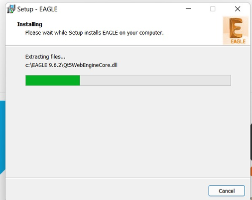
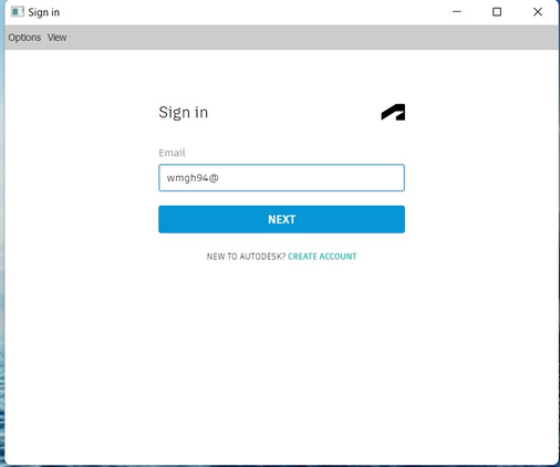
Downloading Eagle software from Autodesk EAGLE.
Add your account and Activated
● FAB library.
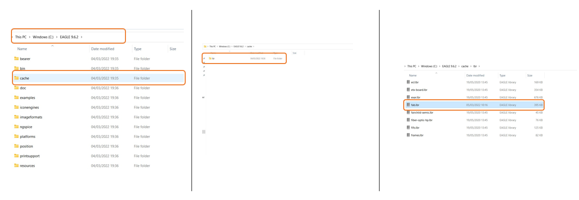
Download the fab library.
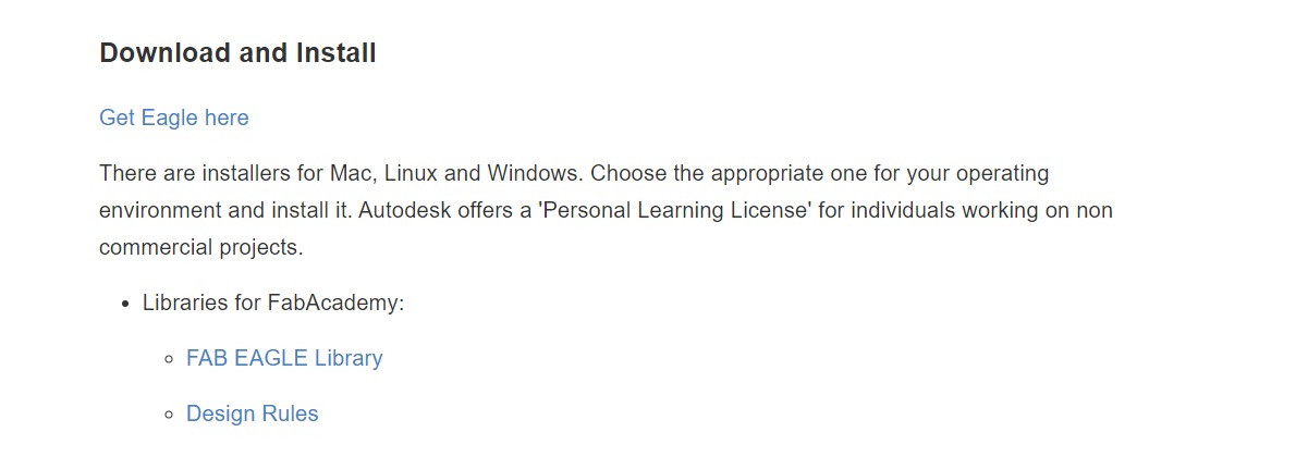
Adding the library to Eagle to add more components to build FAB circuits.
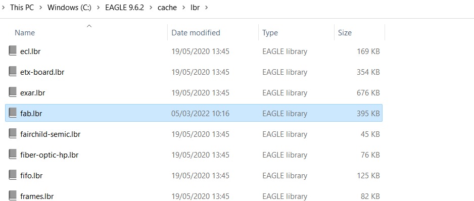
C: > Program Files > EAGLE 9.5.2 > cache > lbr > Add the library file.
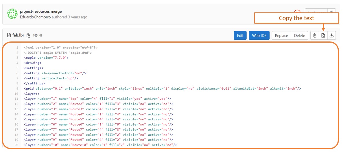
✷Important Step✷
To avoid any problems in the library file Open the fab library from Github and copy the text.
● Redraw the schematic
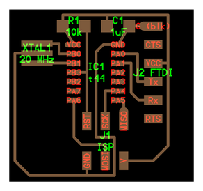
From the Echo Hello-World board. I chose Attiny44-SSU to build my own PCB. hello.ftdi.44.png.
The components we need to use for Attiny44-SSU :
- ATtiny44
- 1 2x3 pin-Header
- 2 10Ω resistor
- 1 499Ω resistor
- 1 uF Capacitor
- 1 6 pin-Header-Male
- 1x06 SMD
- 1 Button
- 1 LED
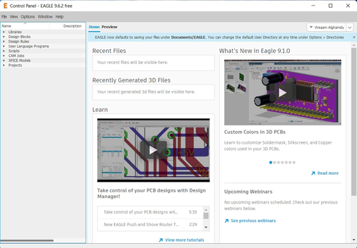
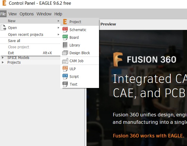
Open Eagle Software then go to
File > Project > New > Rename the project > Schematic
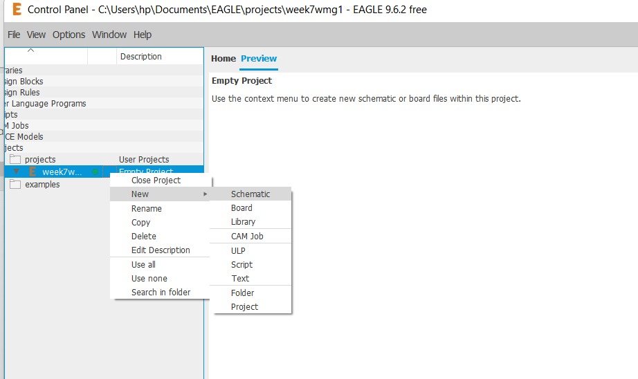
✷Eagle Workflow✷
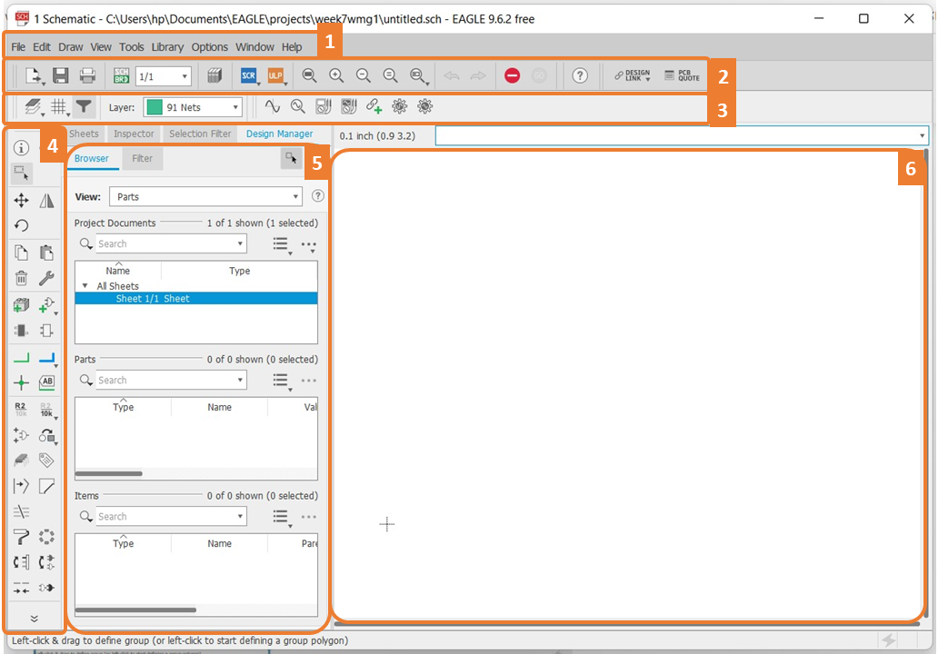
The main parts:
- Menu bar.
- Toolbar.
- Parameter toolbar.
- Command toolbar.
- Coordinate display.
- Working Area.
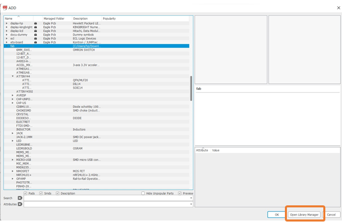
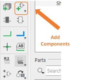
To add
components > Go to add part > then add all the required components

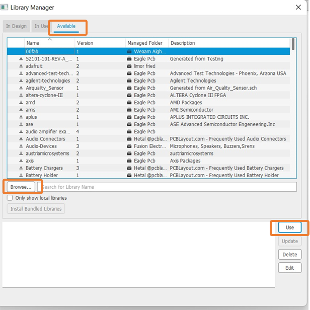
If you don’t find the Fab lbr you can add it# by
open library manager > available > Browse > use
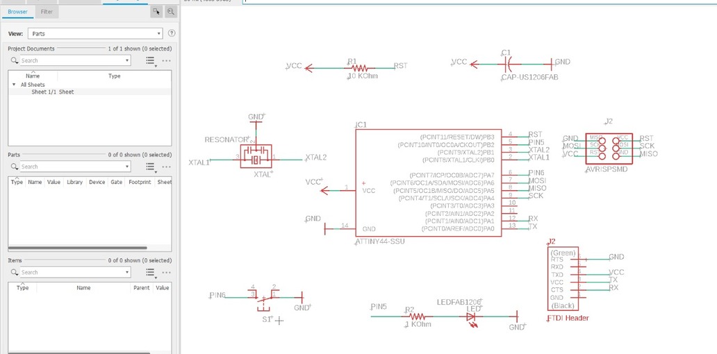
● The Schematic
✷Breaking down✷

“Here I breakdown I spent much time trying to do something I did not know what is it so I ran to my instructor to explain what happened here, he advised me to start from zero and he said you should know the reason behind each symbol and number not just copy what other did! SO I started again I spent a whole (2) days learning from zero, watching many youtube videos, reading many articles, and attending different workshops. until I know a bit more about transistors, microprocessors, power, electrons, and volt. also what is DC and EC now I’m not an expert but at least I know the basics. I remember my despair in highschool when it came to math, physics. after all this, I go back to Nail class to watch and learn more.”
Channel may help for the beginners:
Useful websites for academy students [EAGEL SOFTWARE]:
~Thank you for them~
꧁ Here I start again with new PCB ꧂
I looked to the ATTiny44 Datasheet and now I can read it understand.
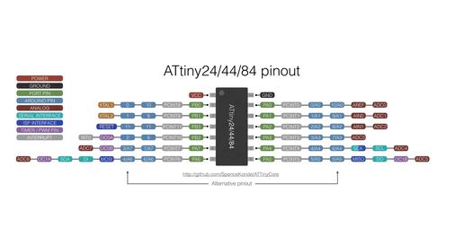
Now I know each component and its name and symbol
- ATtiny44 “ATTINY44-SSU SOIC14” = IC.
- Voltage Regulator”V_REG_LM1117SOT223” = VCC.
- Capacitors “CAP-UNPOLARIZEDFAB” = C.
- Resistors”RES-US1206FAB” = R.
- Push Buttons”6MM_SWITCH” = SWITCH.
- ISP AVR Male Header 2x3 SMD”AVRISPSMD”.
- FTDI Male Header 6x1”FTDI-SMD-HEADER”.
- LEDs”LEDFAB1206”.
- Pads”SMD2_PAD”.
- RESONATOR “Resonator”.
To add
components > Go to add part > then add all the required components
it’s very important to choose the right components Otherwise, the components will not fit on the board.
After I added all the components, I followed the drawing (Nil’s drawing) to connect the components with each others by using net.
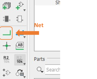
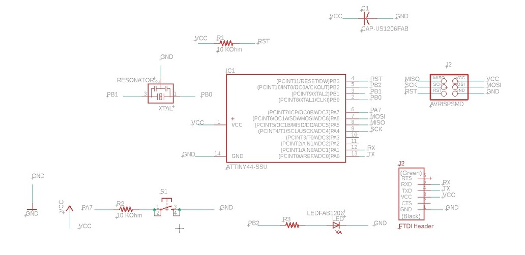
▼ The Schematic After adding the nets ▼
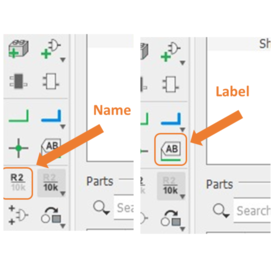
There are two ways to connect the wires, either by connecting the entire wire from one port to the other port
Or by simply naming one end of the wire with the other end connected to it via an icon
Label > Name this is easier and more organized
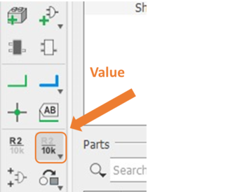
Adding value for Resistor
2x 10K ohm Resistor one between the reset and VCC ports, and the other for the push button.
1X 290 ohms for LED
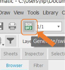
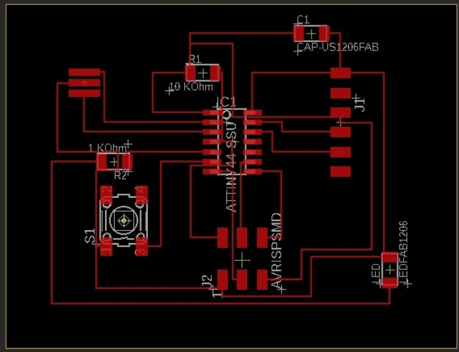
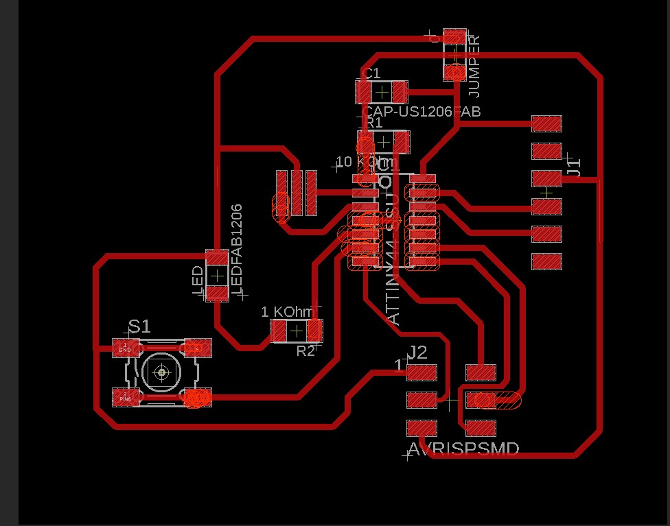
● Creating the board
After finishing adding the components, Name them and give them value now by clicking the Generate/switch to board icon.
its showing like that just drag it in the middle and you can move and rotate each parts.
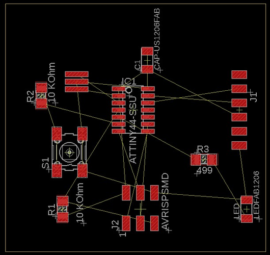
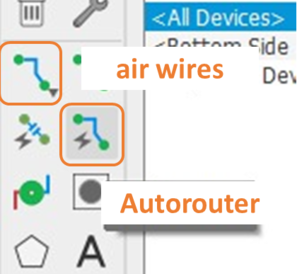
Auto connect by click (Autorouter) or you can connect manually by click (air wires) For me I use Auto router and modify it by move
After connecting everything
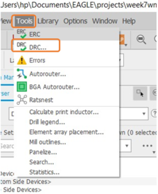
● DRC
DRC or Checks design rules, This command is very helpful to make sure everything is ok, for the final check before manufacturing.
what does DRC do? checks a board against the current set of Design Rules. Only those signal layers that are currently active will be checked.
For the Design Rule , click
Tools > DRC
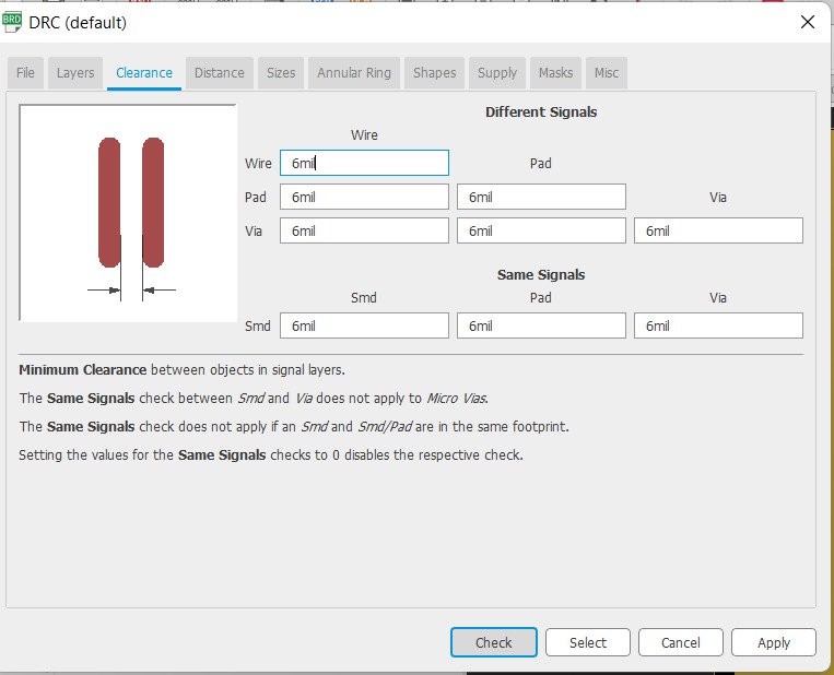
Clearance > 16 mil here
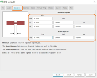
Distance > 16 mil here
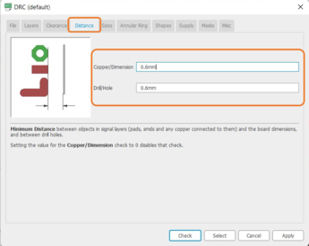
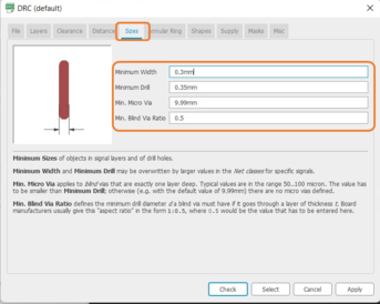
minimum > 16 mil here
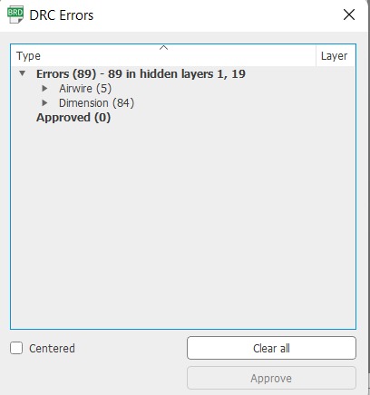
After your setup then click Check to make the software change automatically for your beard be for you mill it
and the message will show you how many errors you have and where you can click Clear all and the software will fix it for you or cancel it and fix it by yourself and your needs
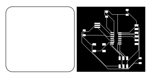
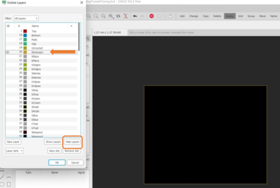
Now we Create our PNG files going into the Layer Settings and disable all layers except the Top layer (traces)
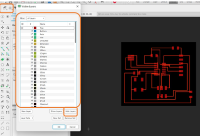
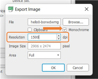
Export the board as an image
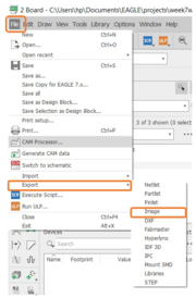
Export the board as an image
File > Export > Image
First trace
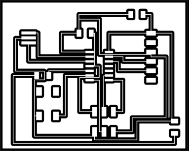
and again same steps with the outline file but here except the dimension layer (outline)

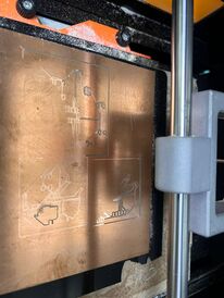
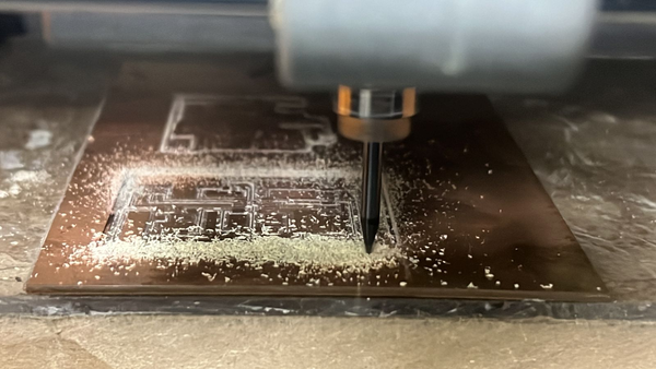
● Cutting the board
As we did In Week5 assignment
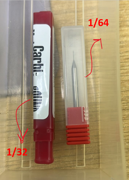
the cutting tool For Trace 1/64 and for cutting outline 1/32
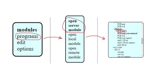
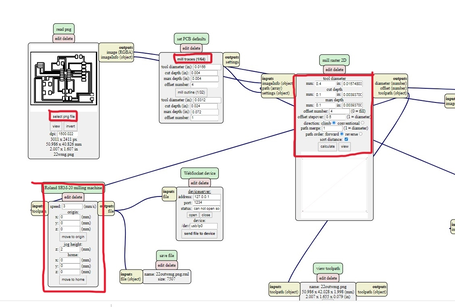
open MODS Set your board design and Right Click
then choose programs > open server programs > SRM-20 > PCB png
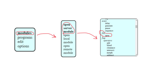
modules > open server module > file > save
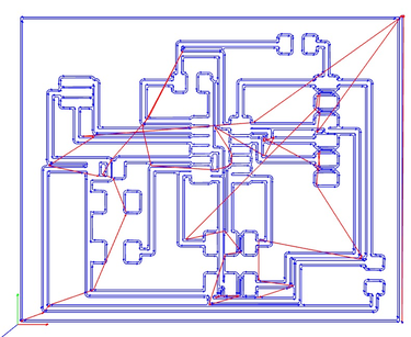
- Trace
make tool diameter to 0.4 mm and the drill depth to 0.1 mm and then hit calculate, make the speed 4 and the XYZ axis to zeros.
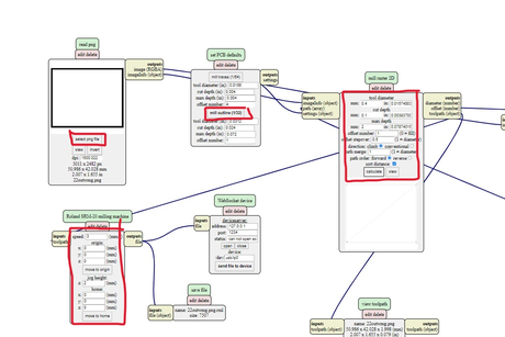
- Outline
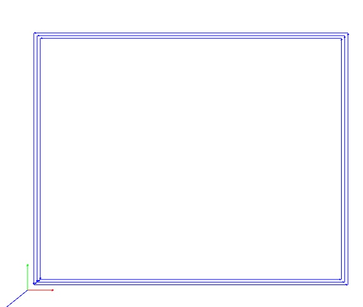
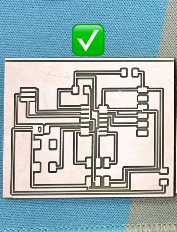
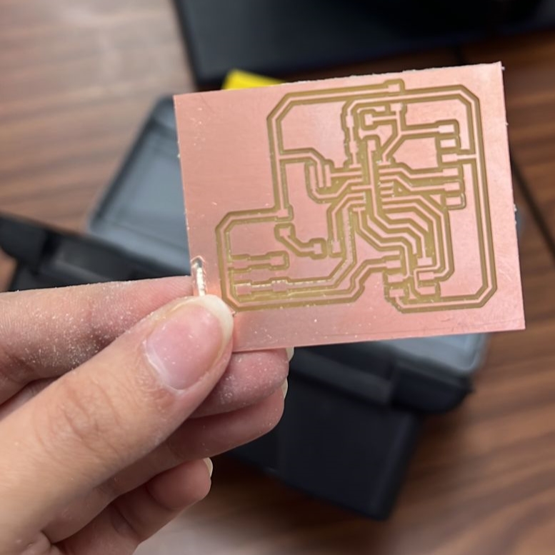
- Final result
 !
!
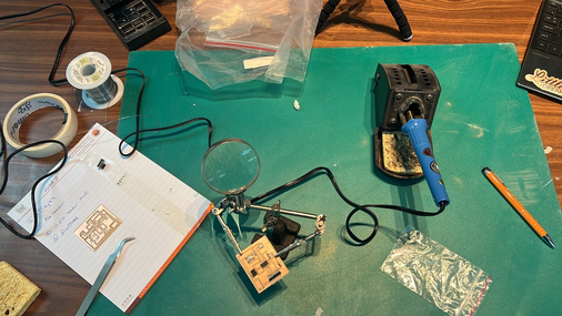
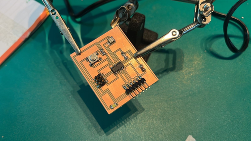
● Soldering
● Programming
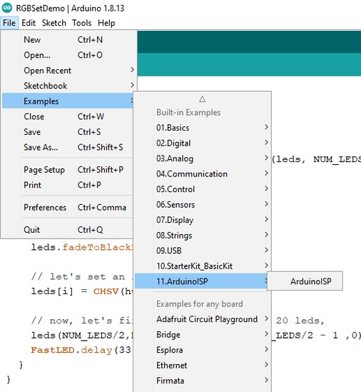
followed this tutorial Program an ATtiny44/45/84/85 With Arduino.
< Follow all steps >
File > Examples > ArduinoISP
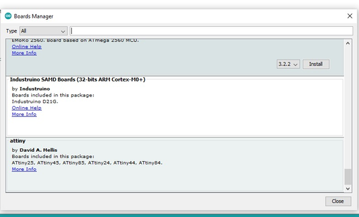
board manager > Add ATtiny
-
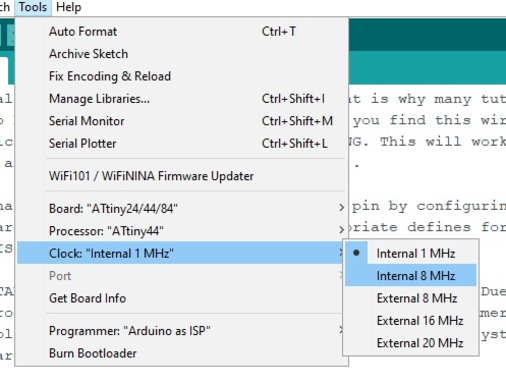
board ATiny24/44/84
-
Processor ATTINY44
-
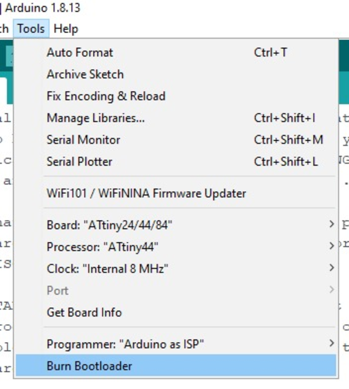
Clock Internal 8 MHz
- Click Burn Bootloader
Here I had Error massage and short circuit
● Problem Solve
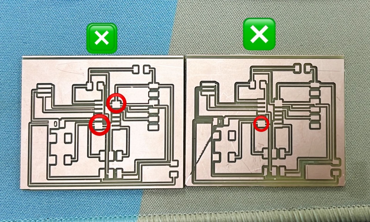
I have to make new board again this time I know where is the problem
Ms.Tasneem she sent me a tutorial to Eagle software and she redraw my board
Thanks for her
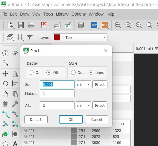
Grid > Size 0.001 mil. to make you move freely
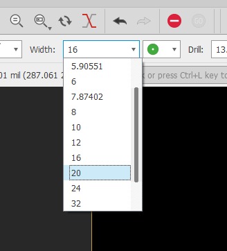
Width wires > 16
Final board
You can see the different between the boards the thickness between the wires and the space between the wires and components
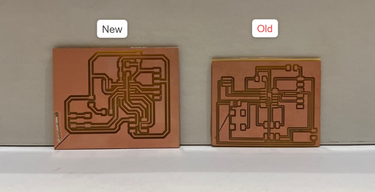
And in new circuit we add a jumper to new arrange
I Solder it and follow the same programming in the up and it’s successfully work LED ON/OFF By button

LED Blinking
LED ON/OFF Button
▶ Files
Code files: