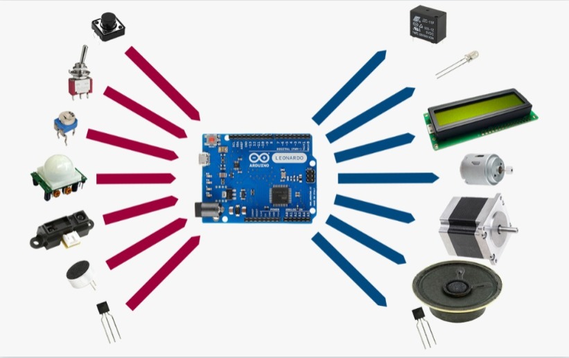
13. Output devices
▶ Individual assignment:
Add an output device to a microcontroller board you’ve designed and program it to do something.
I am using My old board Attiny45 that I have created in WEEK 11.
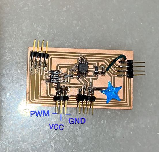
I Designed my board depending on the devices I will use So for the output device week I planned to use servo so to start drawing the schematic you should know the pinout of the microcontroller.
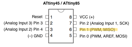
in this example, I connect the PWM output of the servo with the pin 6 (physically the pin 1) of the Attiny 45 for control the servo, the others outputs are ground and the power.
Pulse Width Modulation (PWM)
Pulse Width Modulation is one of the simplest ways to control the speed of a DC motor it works by switching the transistor to reduced power to give it a linear type of control that will result in better speed stability.
Servomotor
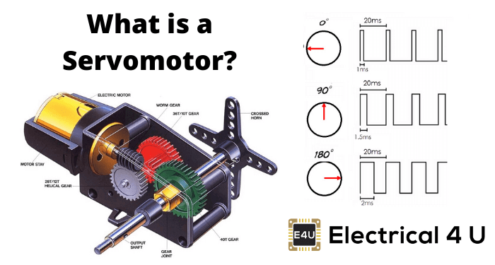
A linear servo amplifier makes the voltage flow continuously to the motor by keeping the transistors going to the opposite section of the drive always. BUT, in pulse-width modulation (PWM), the amplifier will switch the transistors to the opposite section on and off to modulate the voltage flowing to the motor.
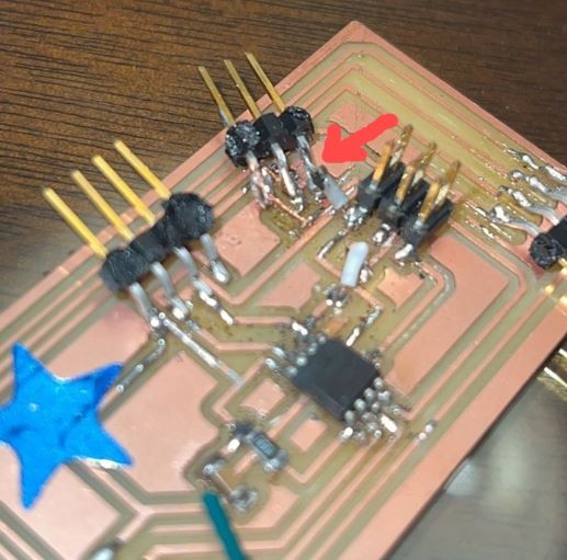
the header broke because I connect my wires very strong so I solder it again
Programming
Using Arduino IDE As ISO to program my microcontroller ‘Attiny45’ as the previous Assignment follow the same progress in WEEK 11
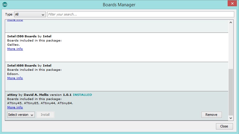
Open Arduino IDE, first add the ATTINY boards to the Board manager by going to > File > Preference
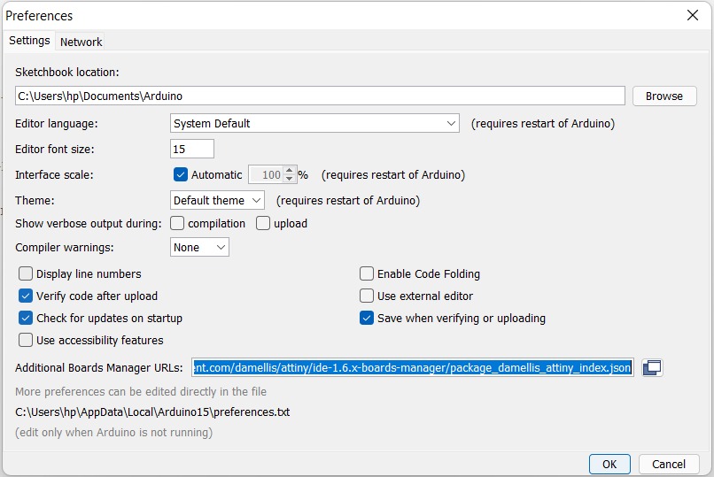
and pasting the following link to the ATTINY package: “raw.githubusercontent.com/damellis/attiny/ide-1.6.x-boards-manager/package_damellis_attiny_index.json” in the field for “Additional Board Manager URLs”
Then go to Tools > Boards > Board Manager, and search for Attiny and select it
then go to “Tools” and select the following :
- Set the Board to Attiny24/44/84.
- Set the processor to Attiny 44.
- Set the clock internal 8MHZ.
- Programmer “ArduinoISP”.
Code Explanation
include the servo library
#include <Servo.h>
  }
Create an Object I Call it here myServo Define the pins Associated with a pin that’s capable of PWM
Servo myServo;
int p=0;
Sweep It’s takes a servo motor and it’s sweeps to shaft from 0 to 180 degrees and then and back again.
myServo.attach(1);
 myServo.write(180);
}

void loop() {
 for (p=0;p<180;p++)
 {
   myServo.write(p);
   delay(10);
 }
 for(p=180;p<1;p--)
 {
   myServo.write(p);
   delay(10);
 }
uploading the code
there is a problem with the servo motor sweeps I find the mistake in my coding
So when I check the sketch I Find I have a mistake with the degree end of the sweep
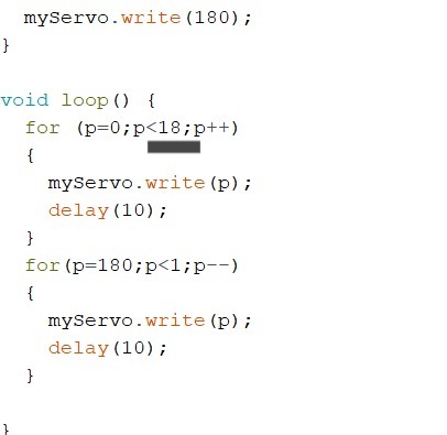
I correct it to 180 and its sweeps very well