3. Computer Aided design
Tasks of the week:
This week the task is Model (raster, vector, 2D, 3D, render, animate, simulate, etc) a possible final project, compress your images and videos, and post it on your class page.
3D software

Autodesk Fusion 360
- Download and install Autodesk Fusion 360 but first you should create an account in Autodesk
Drawing
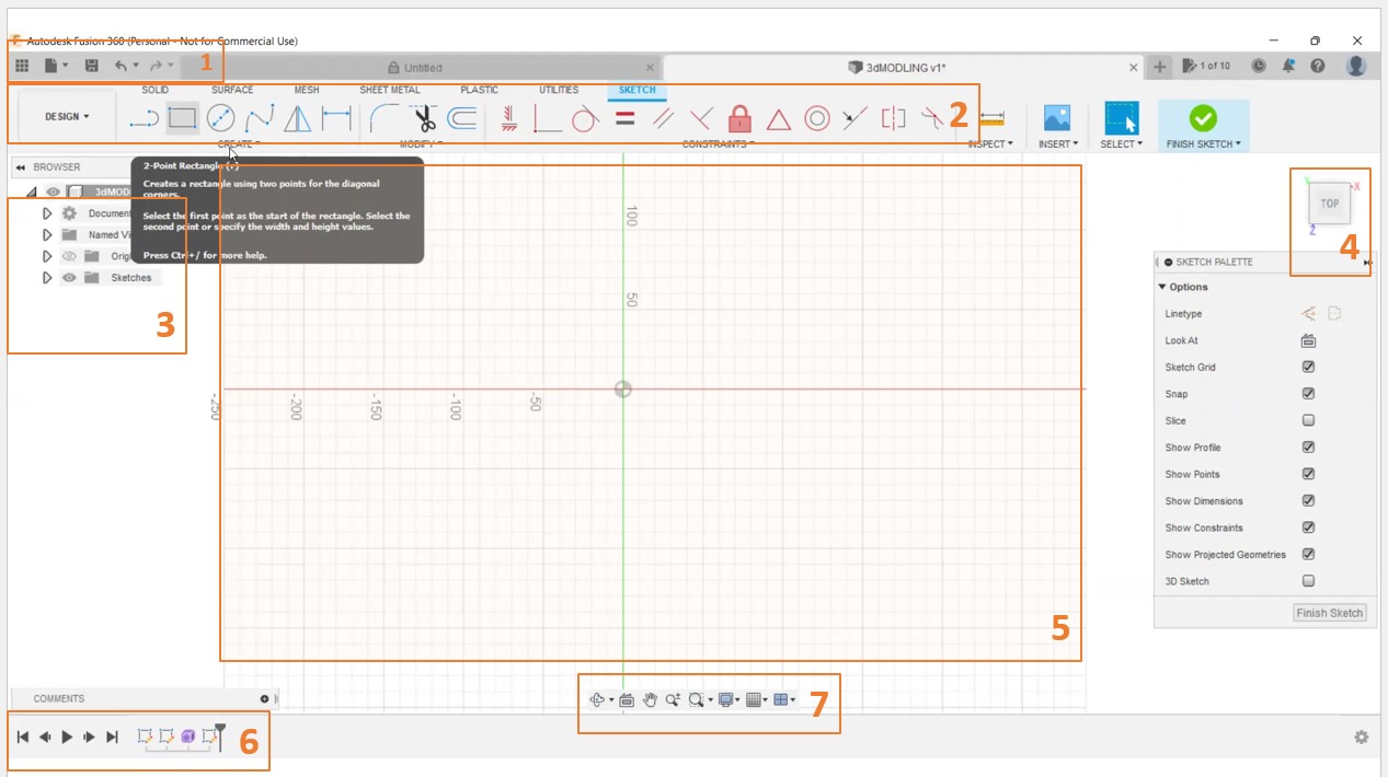
- Getting started with Fusion 360 (Quick tour)
1. Application Bar Create, open, upload, save, export, recover, 3D print, and share designs.
2. The Toolbar is divided into tabs that organize the tools into logical groupings.
3. Browser: Lists objects in your assembly (components, bodies, sketches, origins, joints, construction geometry, etc.)
4. View Cube Orbit your design or view it from different positions.
5. Assembly in the Canvas: Left-click to select objects from the assembly in the canvas.
6. Timeline: Lists operations performed in your design.
7. Navigation Bar: Contains commands used to zoom, pan, and orbit your design.
Now I will start draw and design
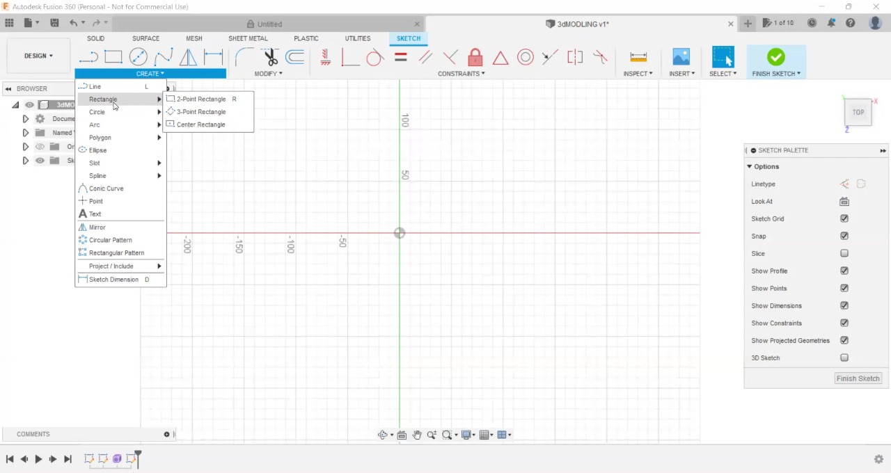
Create >> Sketch >> Line then from the sketch list chose >> Arc sketch
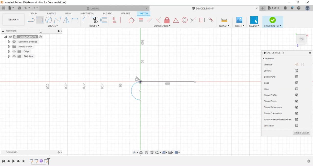
Create > Sketch > Arc now select your sketches (The line and the arc separately)
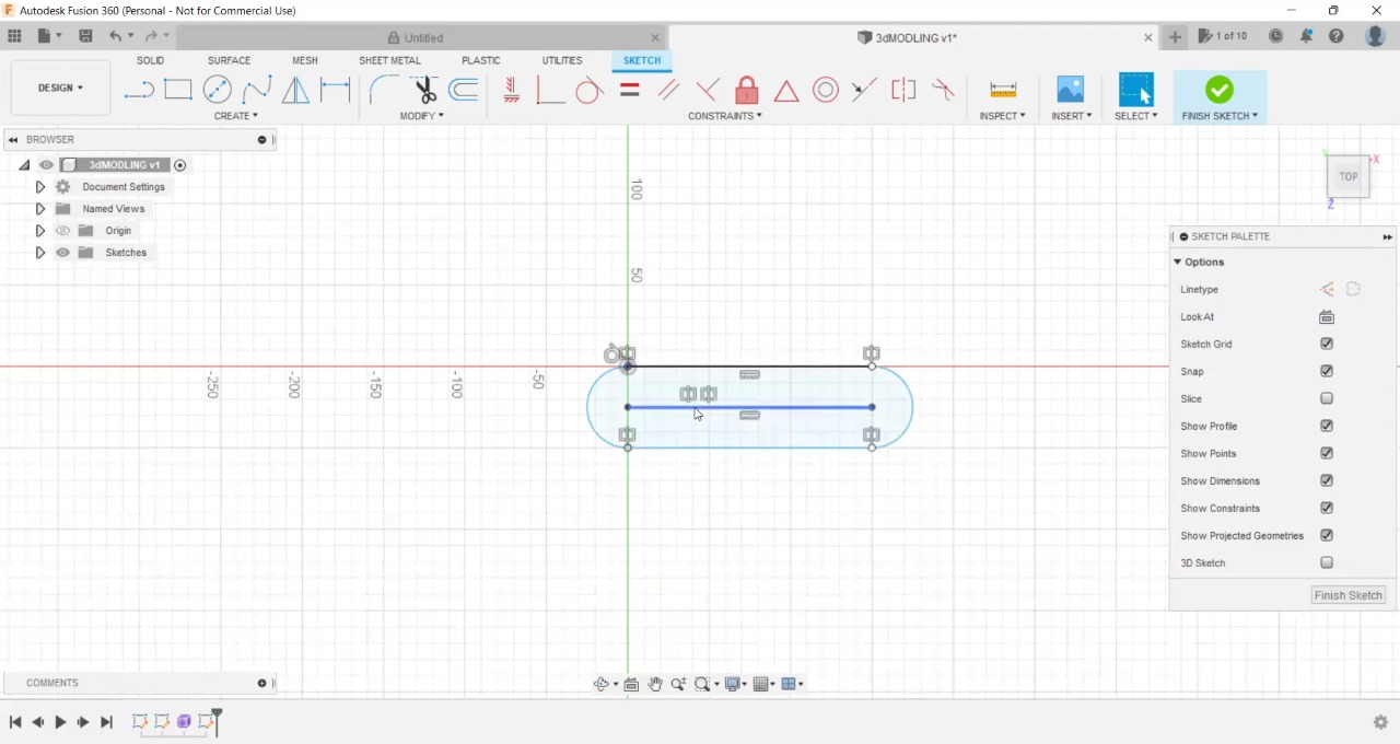
Create >> Mirror >> select the object and the mirror line
Note
to mirror in fusion 360 you need to choose the object and the mirror line , Here I Create two temporary lines, a horizontal line to mirror the line and another vertical line to mirror the curve then I delete the temporary lines.

Close the object and Select Extrude
Create >> Extrude
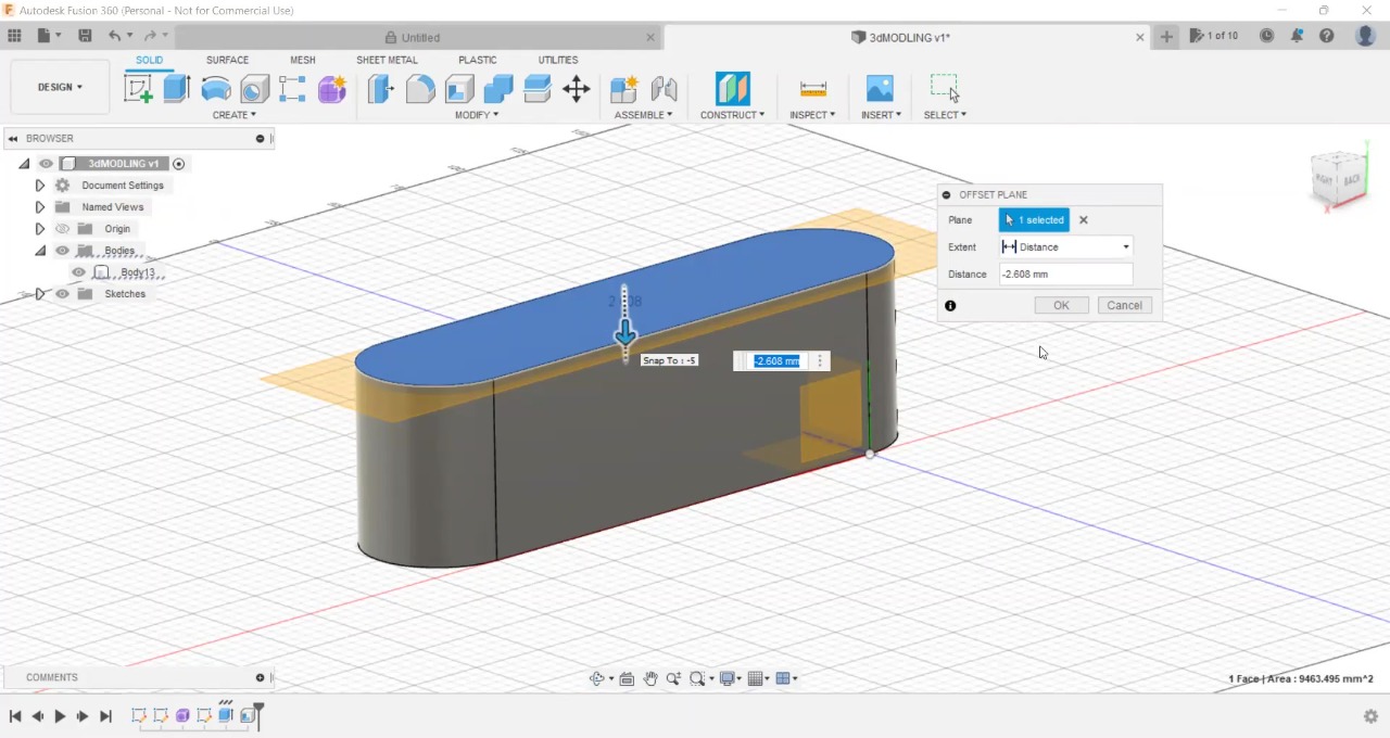
construct >> midplane
To create the lid Click the construct menu then click midplane then you need to select the sides of the object that need to be cut to create a lid for it, then it will create the plan you can move the plane and locate it in any hight you need then click OK.
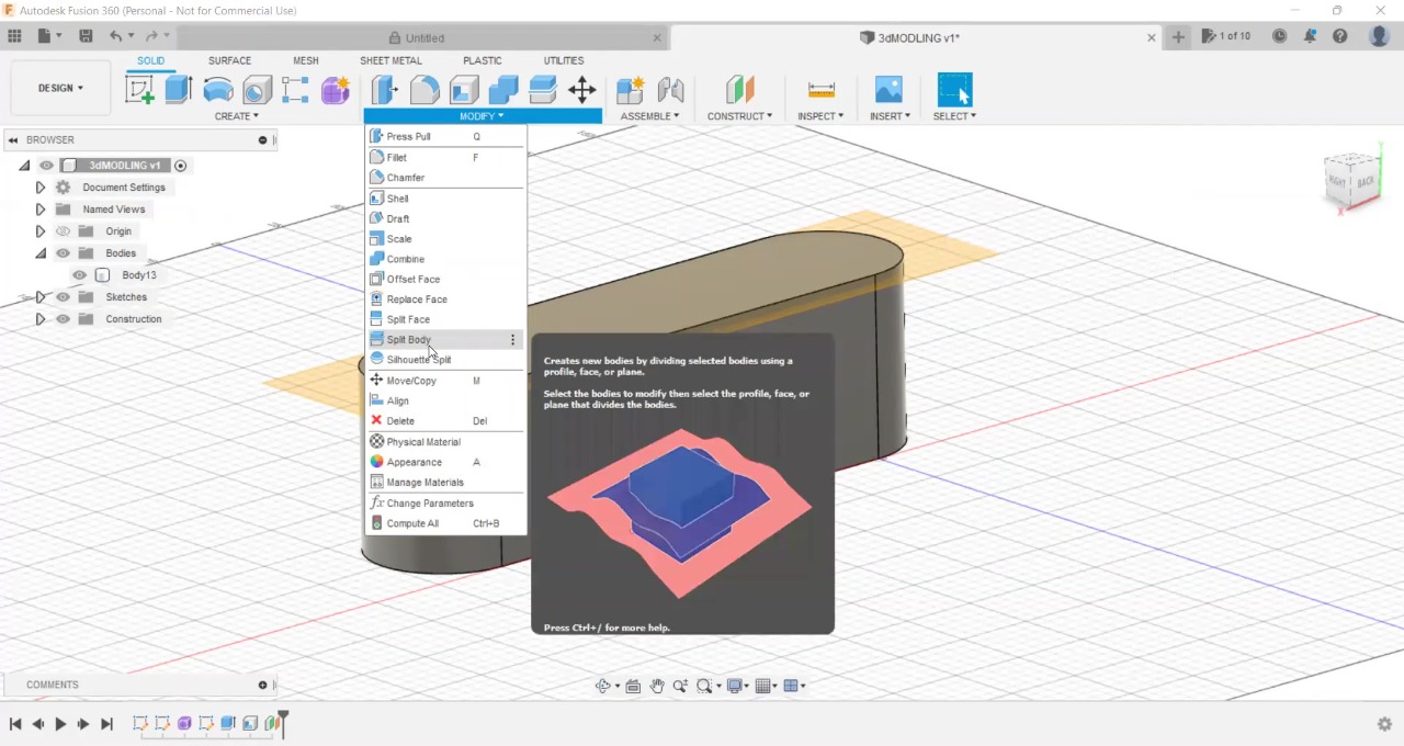
Then go to Modify >> Split body now I have my object with the lid.

Now I move the lid and select the object to make a shell
Modfi >> shell >> 2mm thick
and I fix the extrude height Its very height.
Render
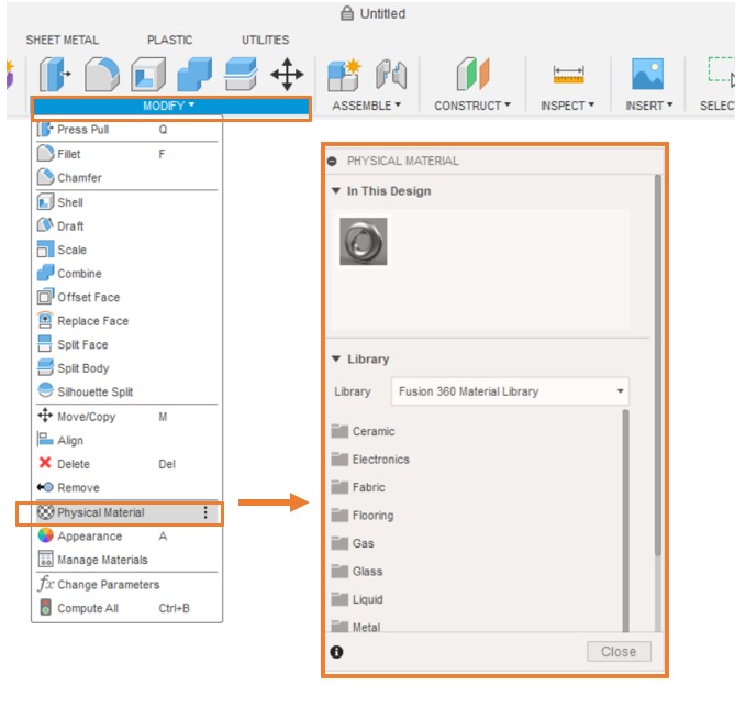
Apply material on your object
Modify > Physical material > New window will open give you different type of materials.
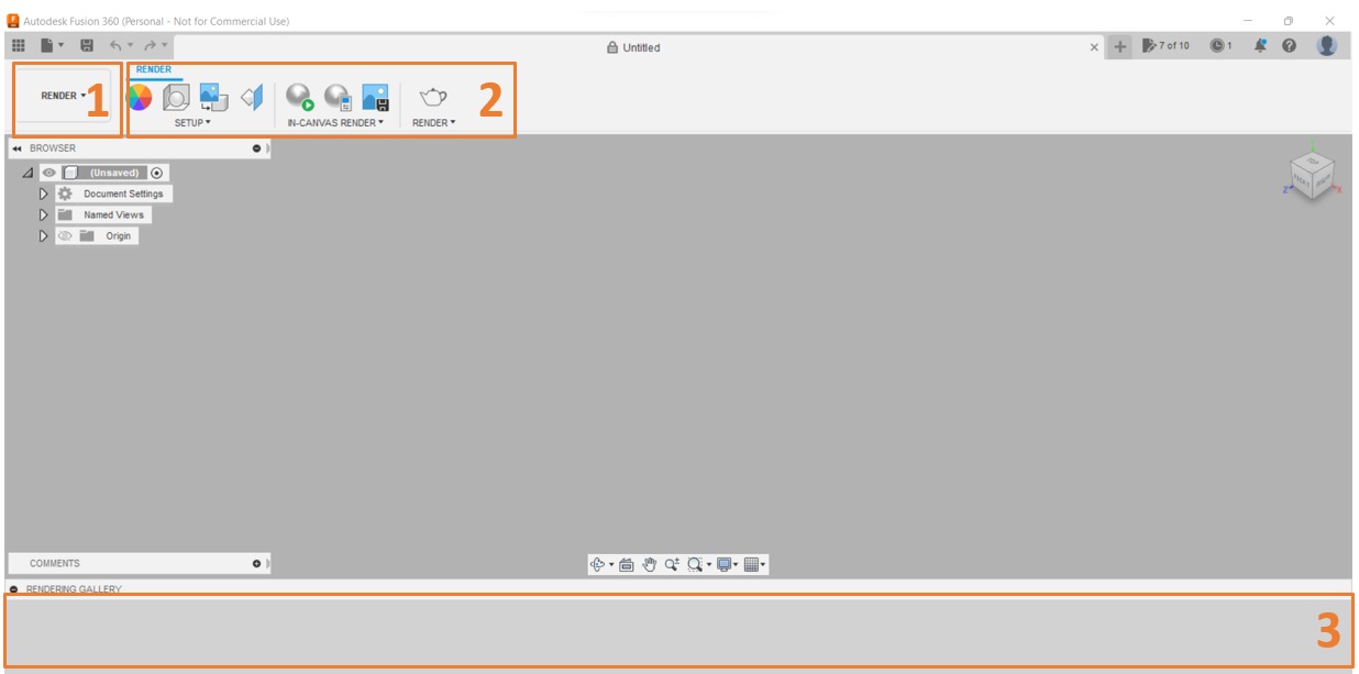
Render
1- Use the Render workspace to render your design.
2- Setup panel provide access to materials, appearances, texture map controls, lighting environment settings.
3- commands to the scene you render.
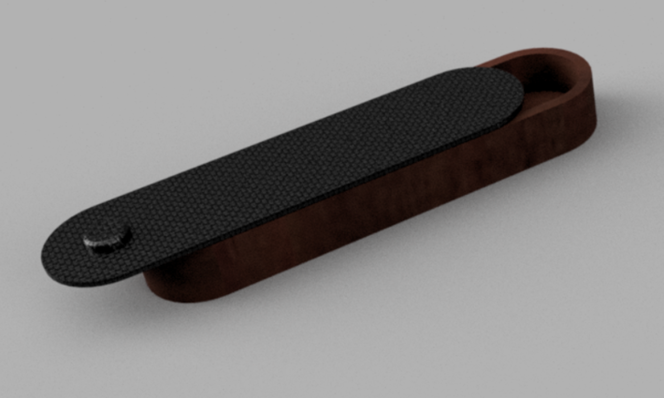
Final project
2D software
InkScape
- Install and setup the Inkscape

Design
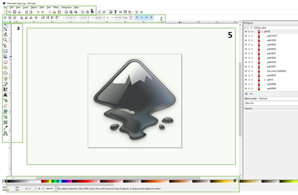
1.The menu bar brings down a set of commands from each menu.
2.List of shape control commands such as size, Color , number of angles, and others.
3.The toolbar contains drawing and texting and panting and more tools.
4.The Color bar.
5.The Canvas bored is the space for drawing and experimentation on which we draw.
Basics
Start with Inkscape
Creating documents
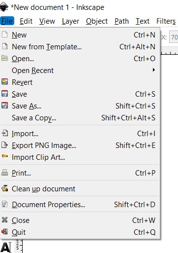
- To create a new empty document, use Fil e⇒ new
- To open an existing SVG document, use File ⇒ Open Inkscape uses the SVG (Scalable Vector Graphics) format for its files.
- To Save document, use File⇒ Save
Drawing freehand and regular paths
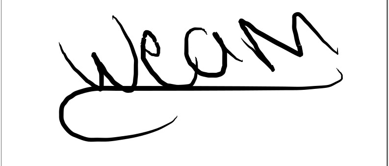
The easiest way to create an arbitrary shape is to draw it using the Pencil freehand tool If you want more regular shapes, use the Pen (Bezier) tool
Editing paths
Unlike shapes created by shape tools, the Pen and Pencil tools create what is called paths. A path is a sequence of straight line segments and/or Bezier curves which, as any other Inkscape object, may have arbitrary fill and stroke properties.
Creating shapes

Click on the Rectangle tool in the toolbar on the left, As you can see, default rectangles come up with a pink fill and a black stroke (outline), and fully opaque. We’ll see how to change that below. With other tools, you can also create ellipses, stars, and spirals:

The Tool Controls bar for a shape tool is another way to tweak a shape; these controls affect the currently selected shapes (i.e. those that display the handles) and set the default that will apply to newly created shapes.
Trace bitmap
Import an Image to add it in my design there is 2 ways to import from file > Import OR Drag and drop
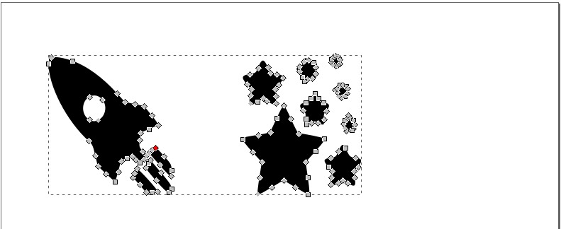
Path > Trace bitmap
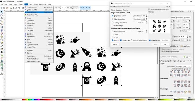
To convert The pixel image to vector image
Generally the more dark pixels in the intermediate bitmap, the more tracing that Pixels will perform. As the amount of tracing increases, more CPU time will be required, and the
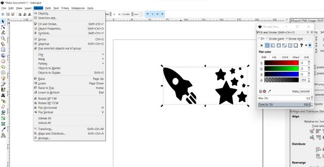
Fill and storke
Object > Fill and stroke
Probably the simplest way to paint an object some color is to select an object, and click a swatch (color field) in the palette below the canvas to paint it (change its fill color).
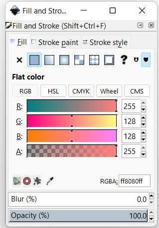
You will see that the dialog has three tabs: Fill, Stroke paint, and Stroke style.
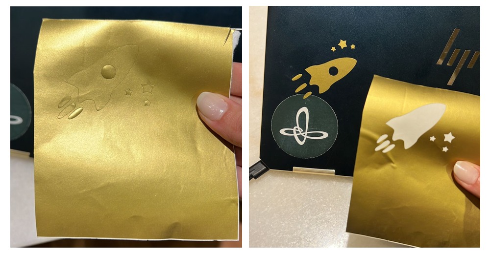
Using Inkscape to Create Laser Cutter files of Vinyl cuter
Here I cutting sticker for my laptop with Vinyl cutter
Compress and resize Image and videos
▶ Files
3dMODLING v2.stl 3dMODLING v2.f3d space sticker.svg