Final Project
Finally
the final project YAAY!

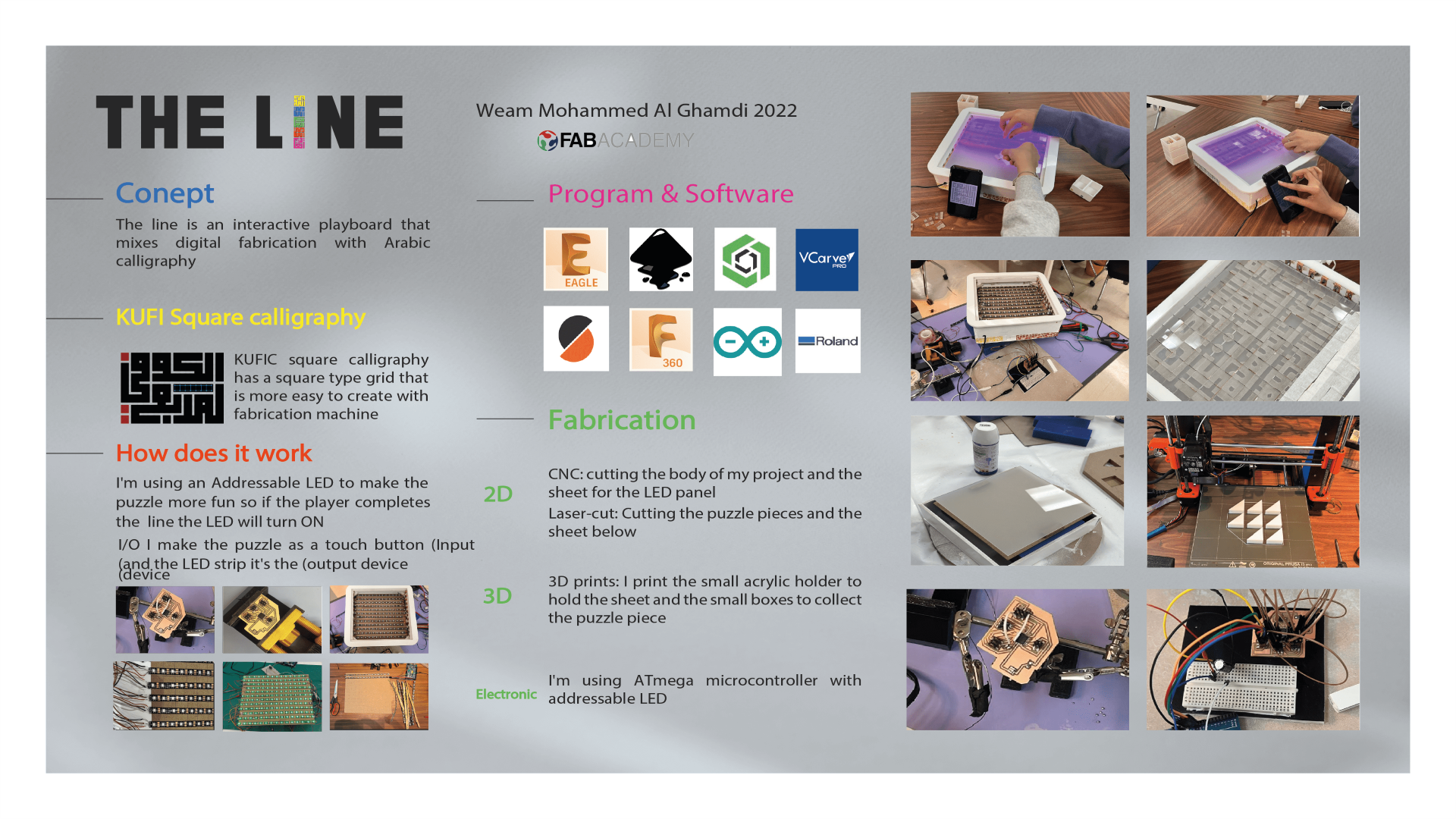
THE LINE
its interactive play bored with arabic touch since i start fabaacademy I want to work on a project that combines Arab art and digital fabrication in a modern way. After researching Arab arts, I noticed that what distinguishes Arab art most is Arabic calligraphy.
▶ Idea Explanation
WHAT
the line’s an interactive playboard working like an interactive puzzle
WHY
this idea came after we worked on one of my favorite projects in FABLAB JUBAIL is the interactive board that we created for the national Saudi festival day.
( We create an interactive playboard to explain to people the identity of the Saudi national day and the idea behind it was very funny and everybody liked it including kids they came to play and ask about the idea so they play and learn ).
in addition, I want to add a personal touch that presents my origin, and as everybody knows the Arabic calligraphy is the most unique and famous art so I planned to work on a project that mixes the digital fabrication with Arabic art
HOW
by creating a playboard to make my idea more fun and interactive for adults and kids and you can share it and enjoy it with everybody.
▶ Fabrication part
● Design the body

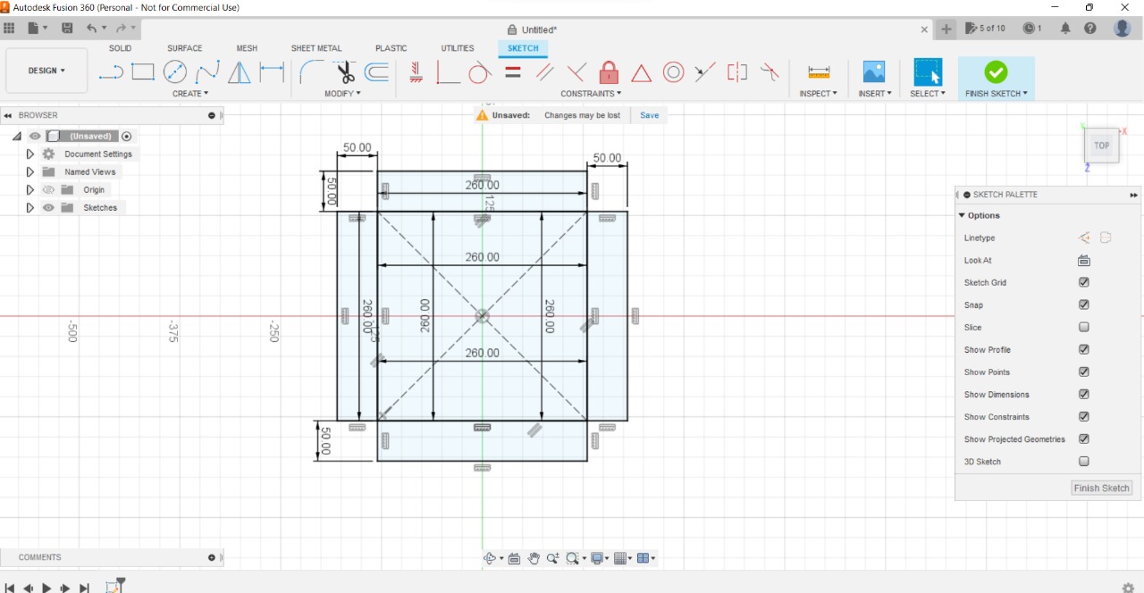
I start designing my box using fusion 360 I explain it with details in WEEK4.
With the sketch tool, I draw all the box faces and Extrude it
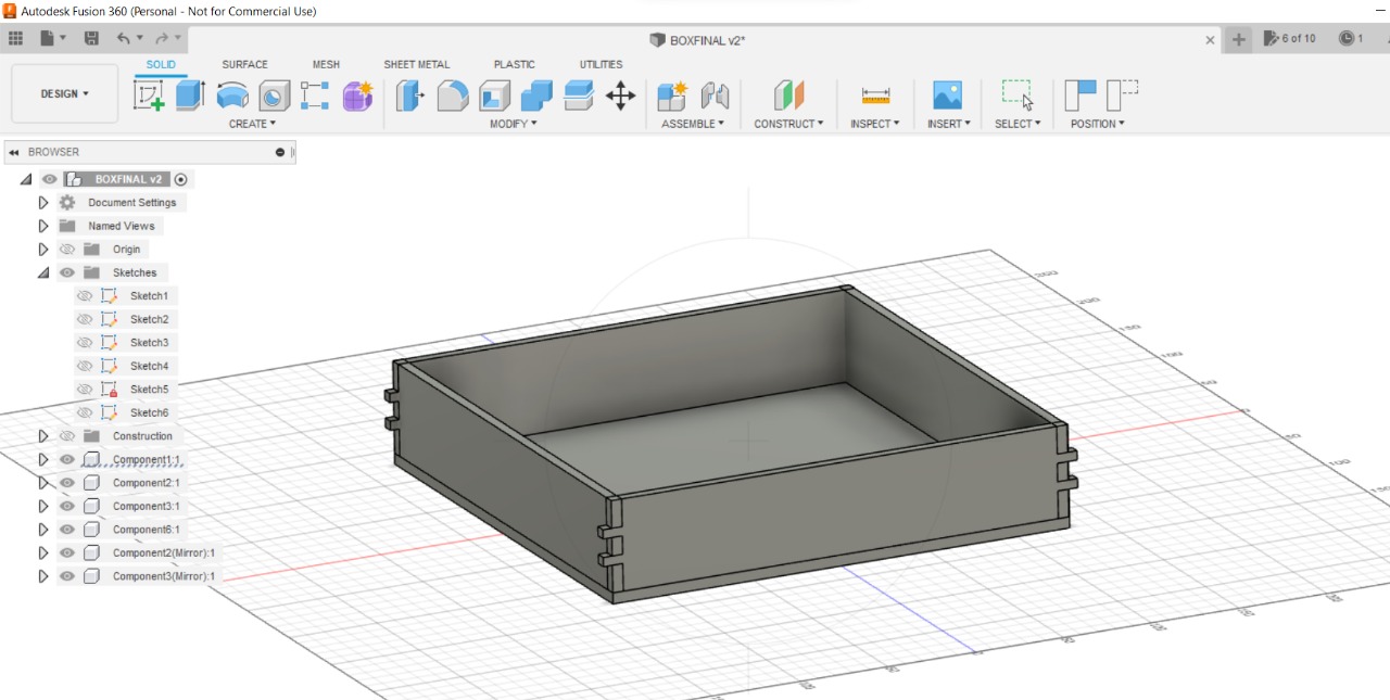
Now I am drawing the sheet to stick the LED strip
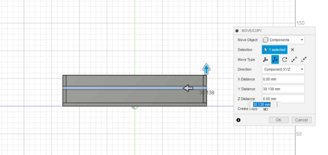
here I finish draw all the layers I need
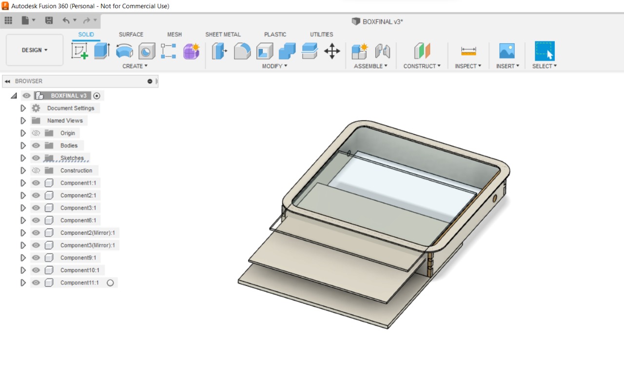
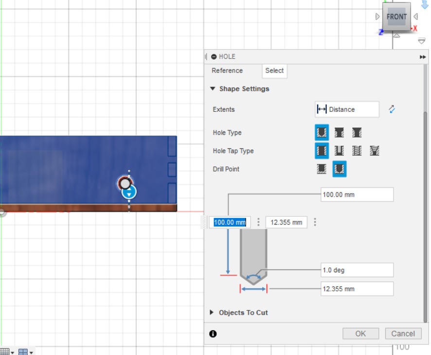
Add the frame in the top
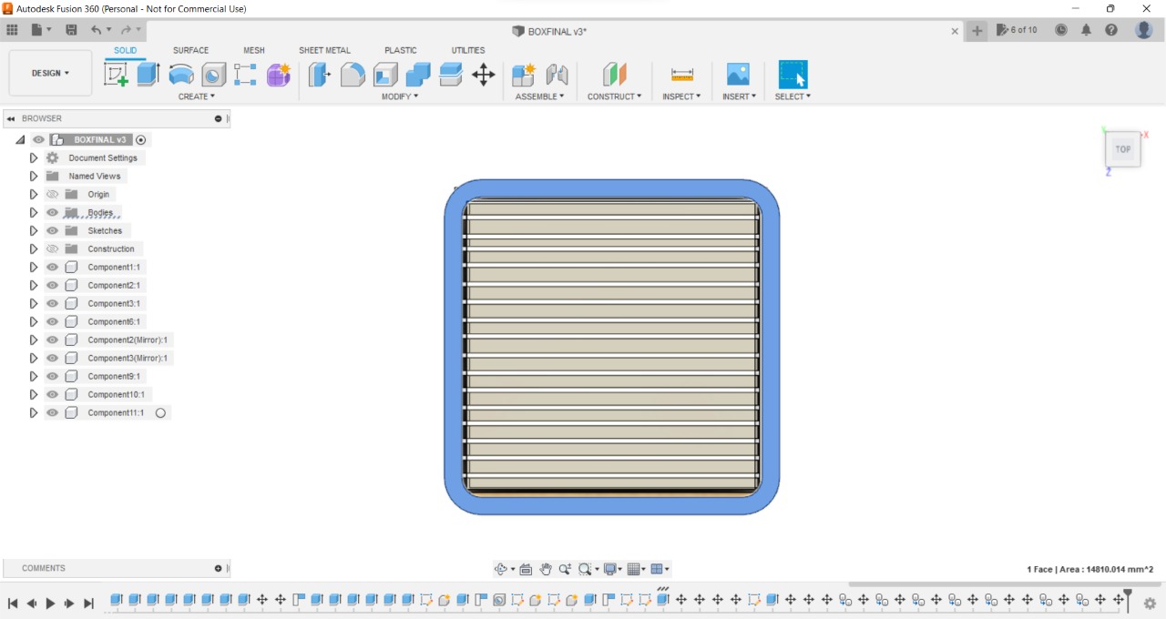
Add the power supply hole
● Cutting by machines
1. CNC
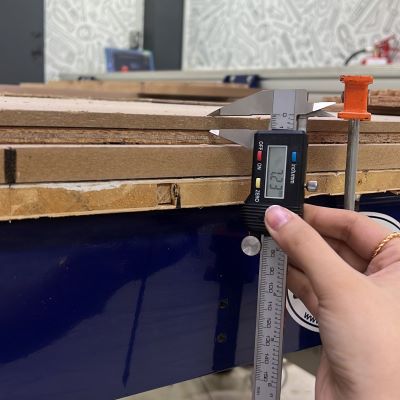
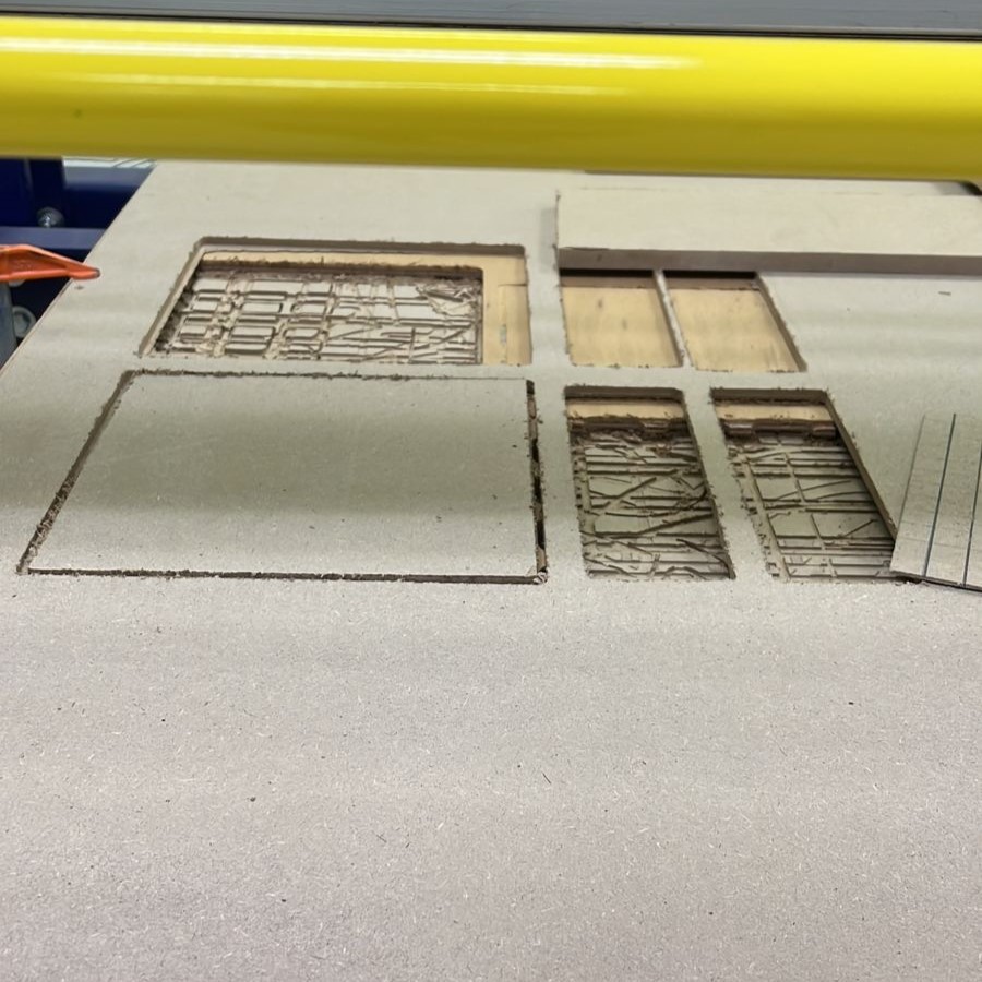
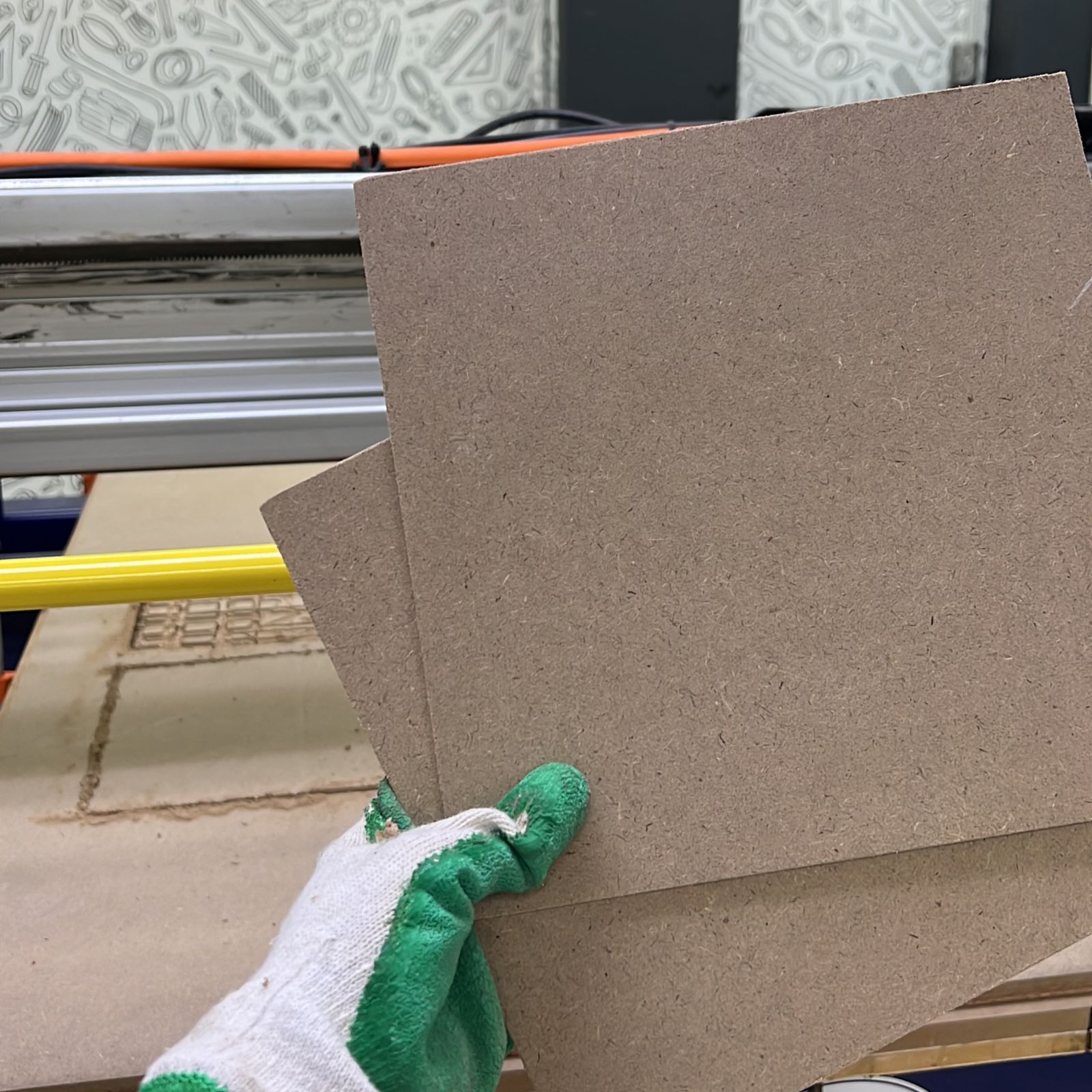
for the outside body of my project, I’m using MDF (8mm) thick.

Using Vcarve to set and cut my design (For more details in how you use Vcarve check here WEEK8.
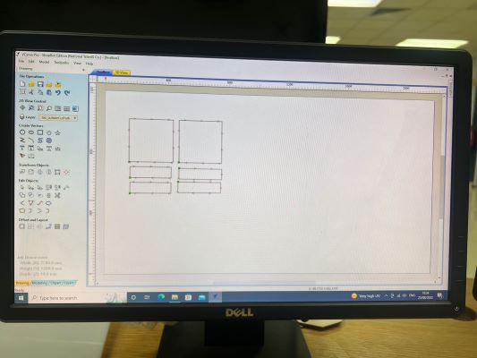
finish the cutting part in CNC machine
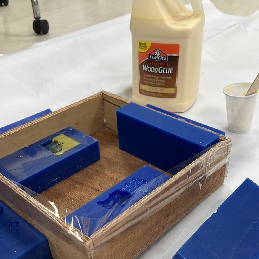
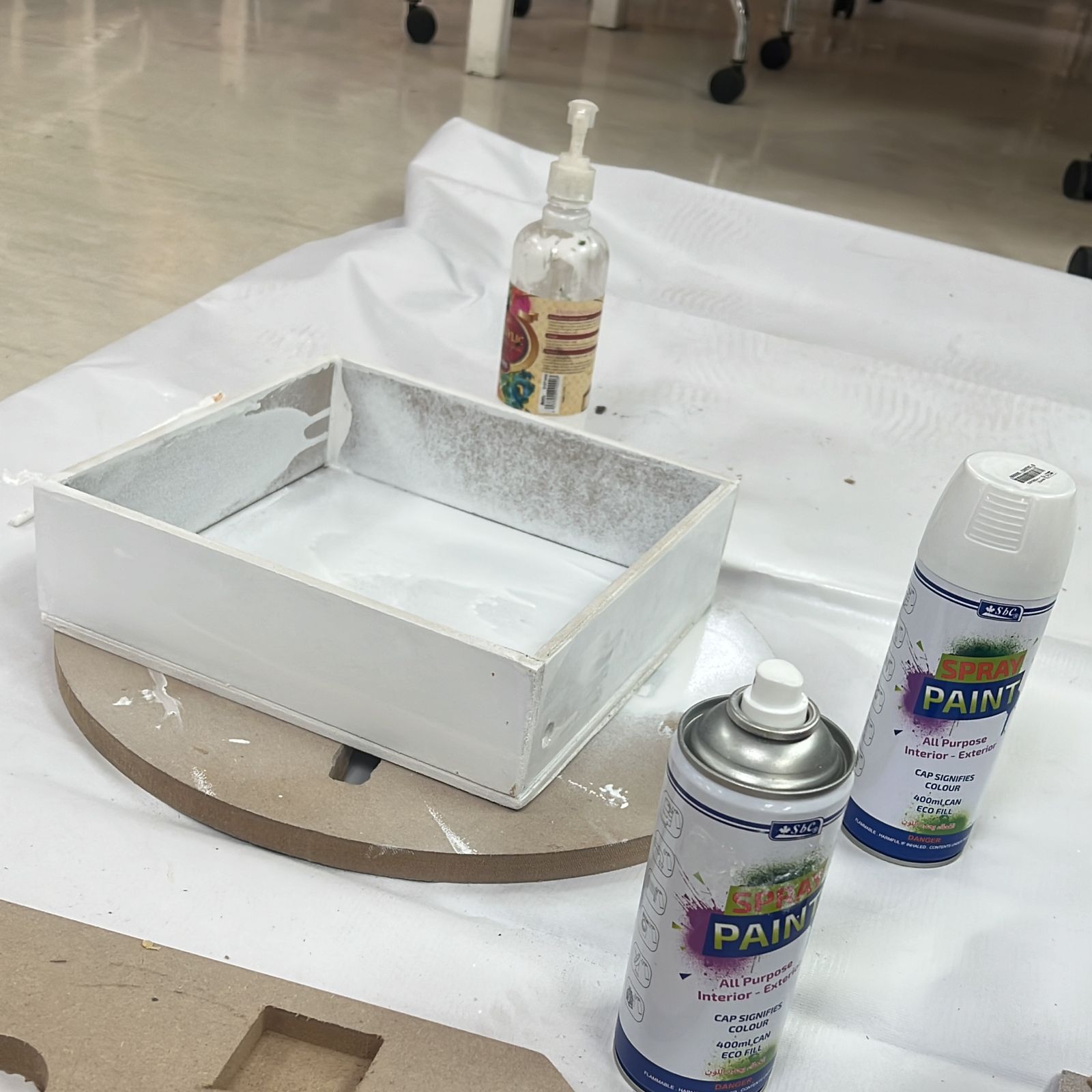
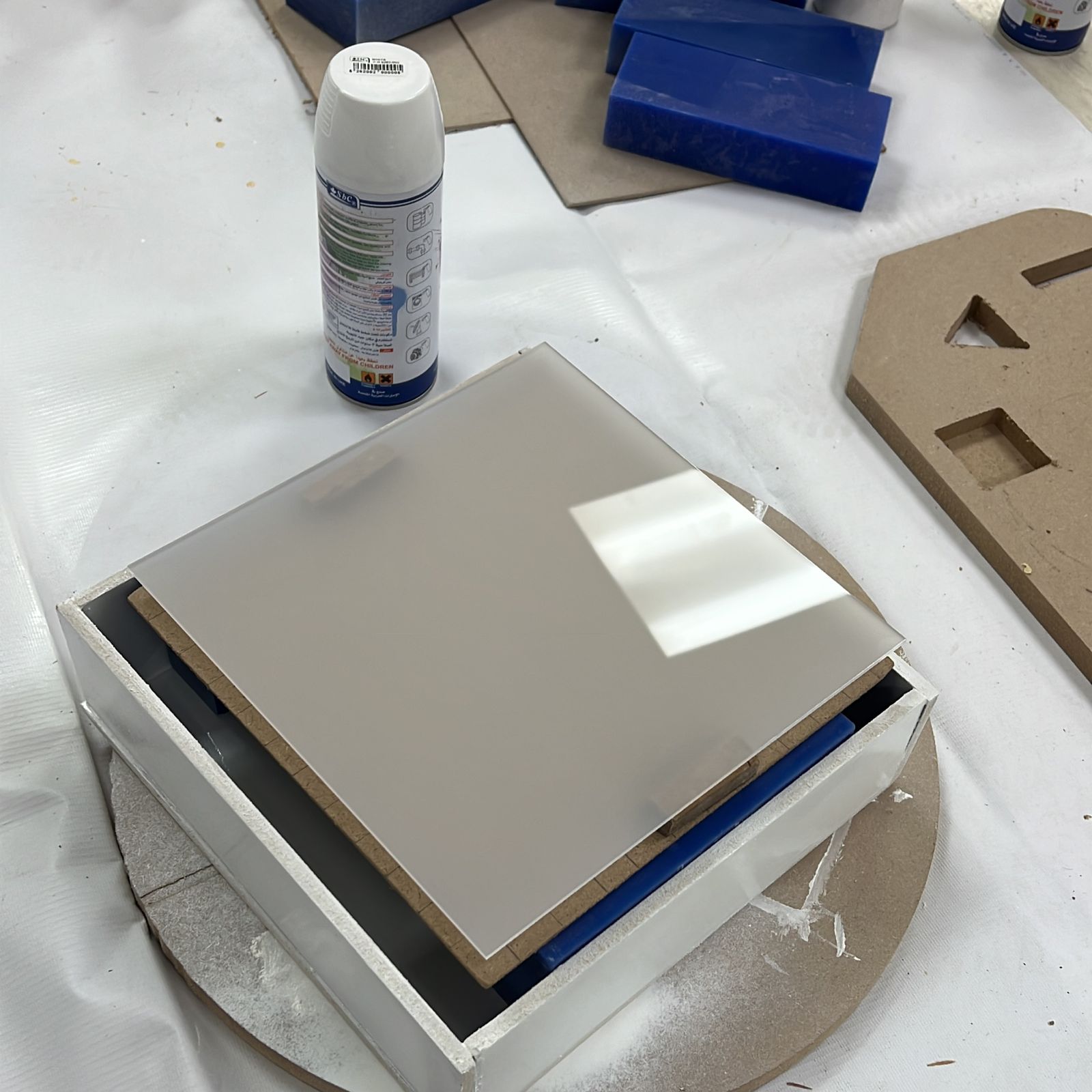
now I use wood glue to stick all parts together and paint it
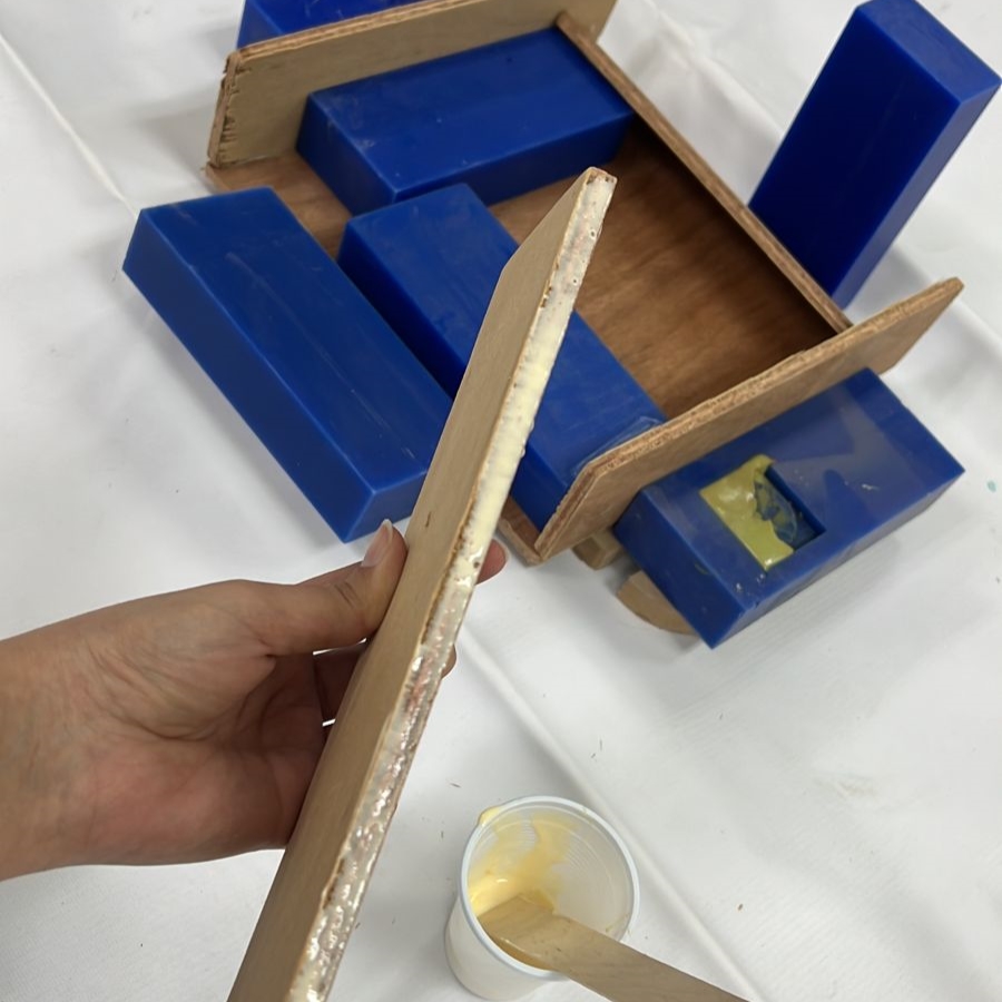
Using spray to make the perfect coat better than using a brush and color
Sheet No.2
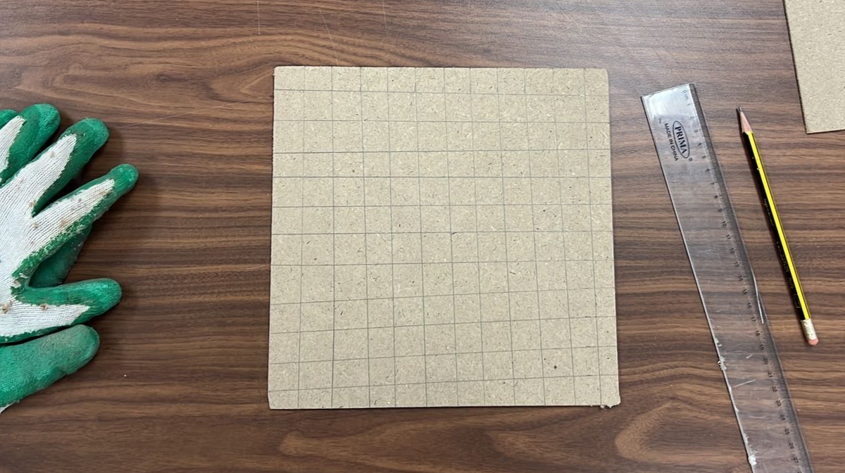
Now I Start to cut Sheet No.2 the Sheet I will stick the LED strips on it. (((My plan is to build an RGB matrix by using LED WS2812B 300 LEDS))) for this layer I’m using MDF 3mm thick.
Final cut
I draw the grid of my LED sheet manually.
2.Laser cut
Layer No.3
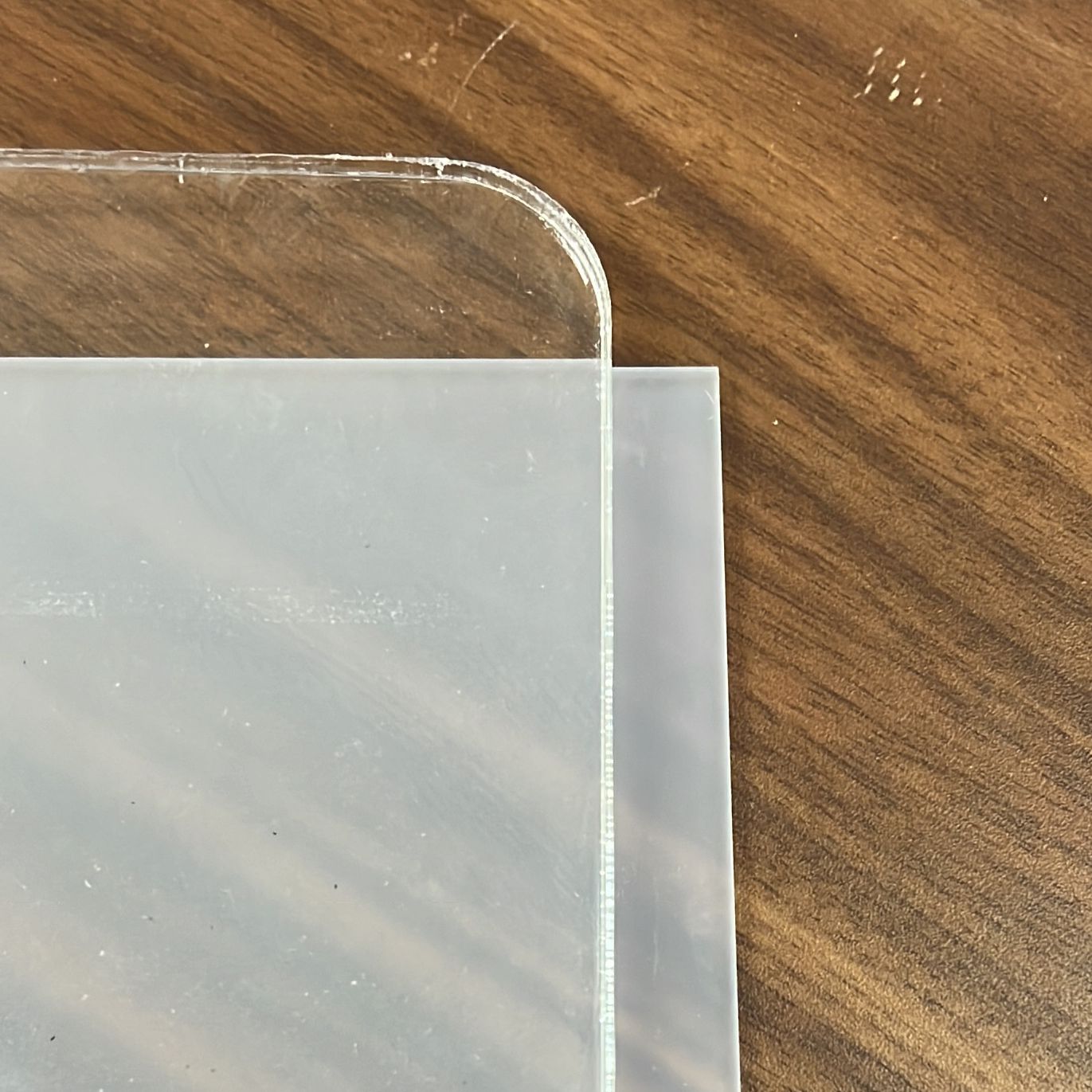
for this Sheet, I’m using semi-transparent Acrylic 3mm thick to make the light coming from the LED Strip in a fade mood.
Final cut
Sheet No.4
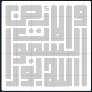
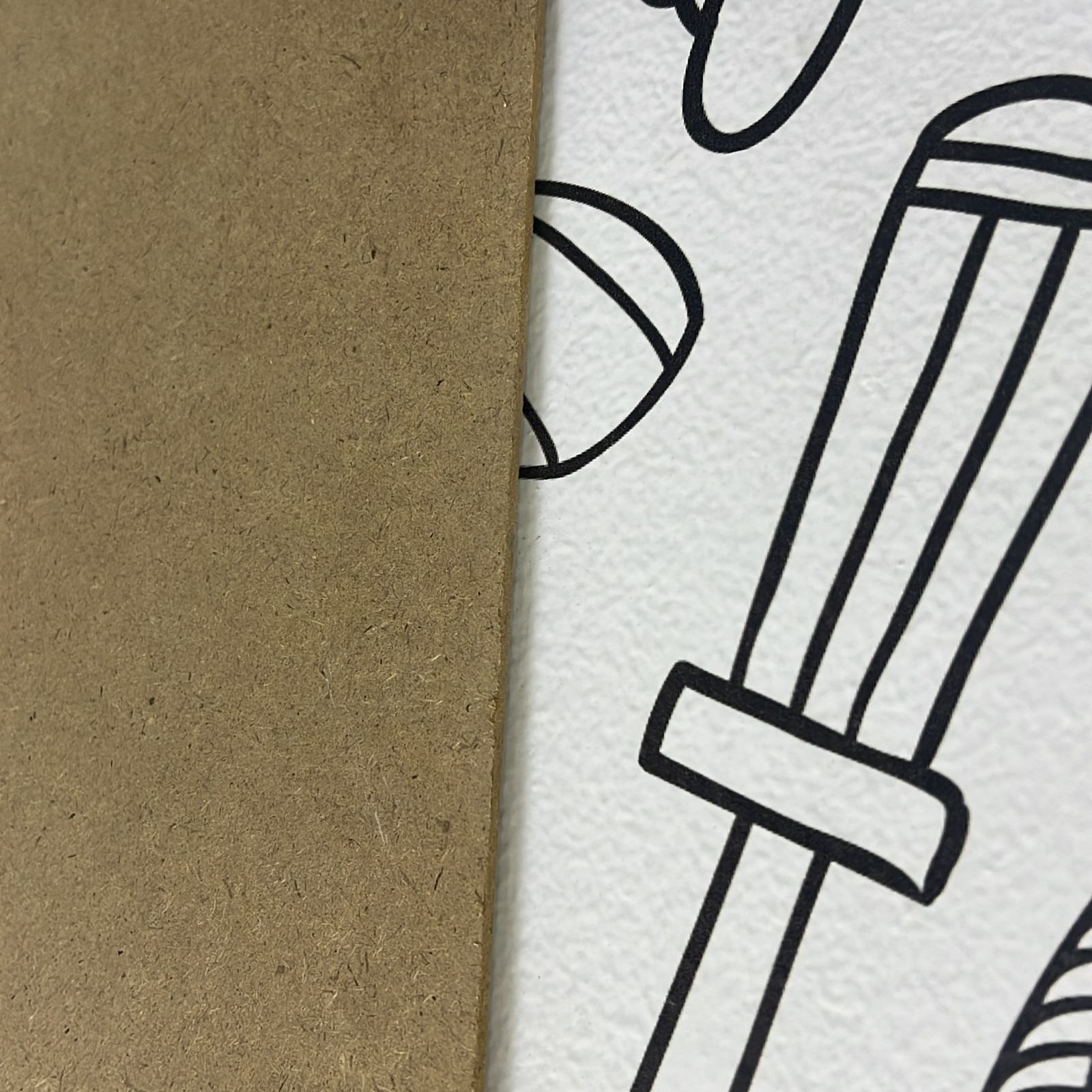
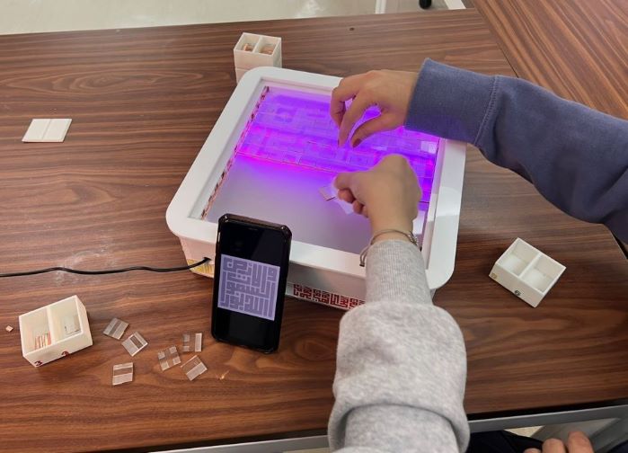
the puzzle sheet (it’s changeable) BUT As I mentioned above, I want to add an Arabic touch to my project. for the puzzle part, I chose to create Arabic calligraphy in the Kufic square font because the grid of the font type is in a square shape which is easy to create in a fabrication machine I chose.
I searched for an Arabic script that fits properly with my design ( الله نور السموات والأ رض) which means the God is the light of the earth and the sky.
✶ Kufic square - Arabic calligraphy ✶
Kufic script (Arabic: الخط الكوفي) is a style of Arabic script that gained prominence early on as a preferred script for Quran transcription and architectural decoration, ] Kufic script is characterized by angular, rectilinear letterforms and its horizontal orientation.
If you are interested to know more about Arabic calligraphy check the website - Arabic Calligraphy

and if you want to try Kufic square calligraphy this website gives you a good experience with a ready grid to write - Type grid
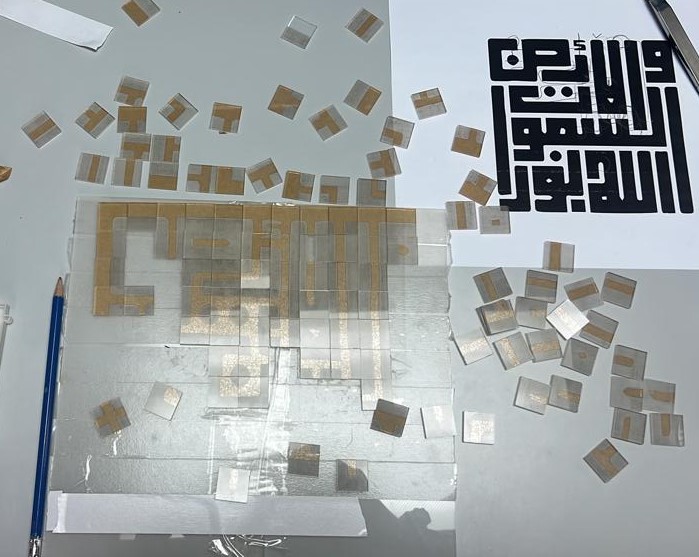
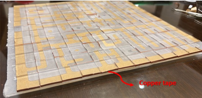
The copper tape
After arranging all the pieces of the puzzle I cover it with copper tape
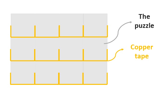
To the copper tape, I cover the pieces from the bottom and half of the two sides to be sure there is no short with another line
Here Finally finish all the pieces with copper tape
Sheet No.5
The frame
this is the last Sheet in the fabrication part and it’s with a laser machine, I cut 6mm white acrylic to create a frame on the top.
▶ 3D printer
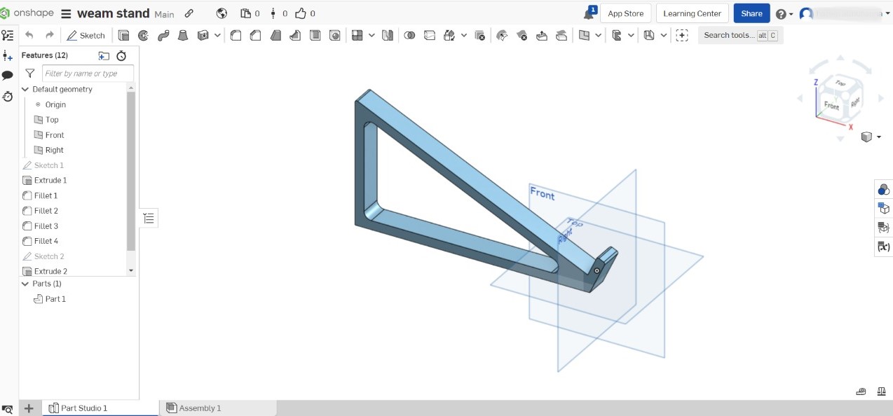
1- Holder
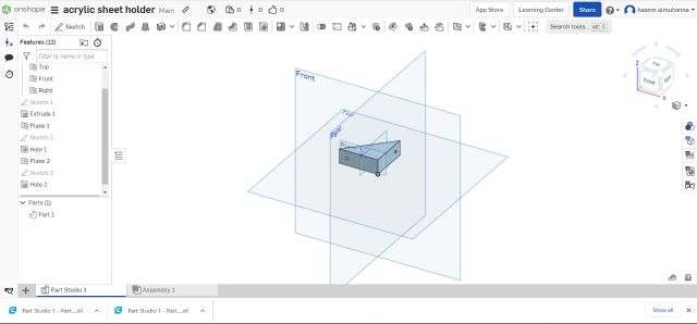
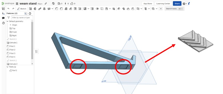
By using Oneshape I design a holder to hold the sheet inside the box
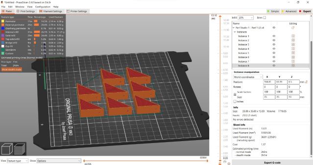
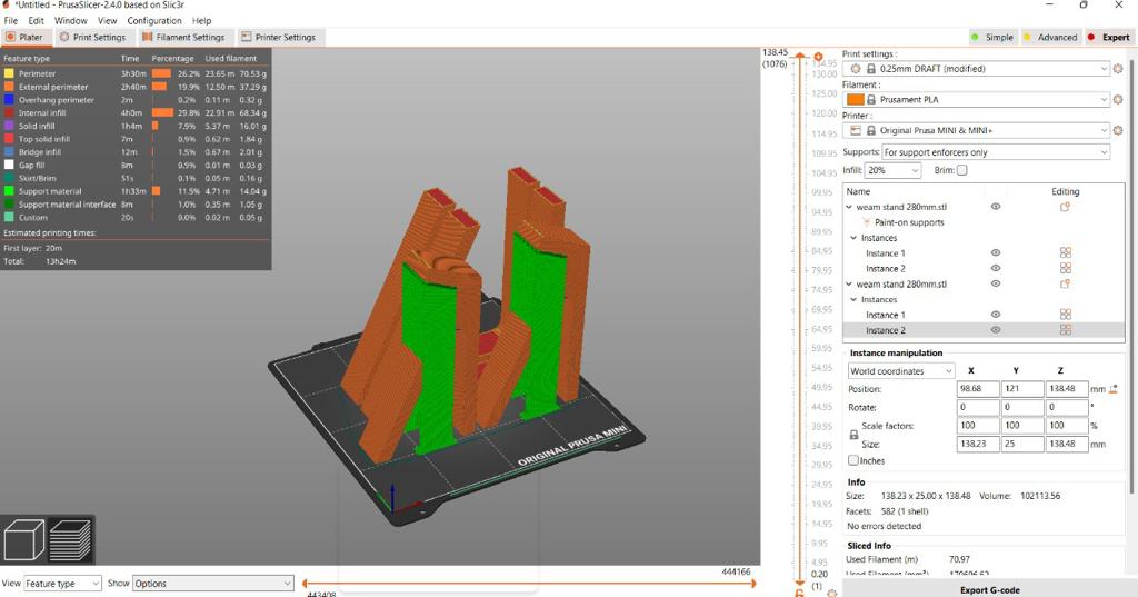
With prusa slicer, I copy my object to 8 copied because I need it to handle the LED panel and the transparent sheet under the puzzle.
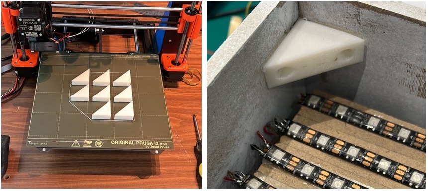
Final modeles , I stick it in the corner to hold the sheets
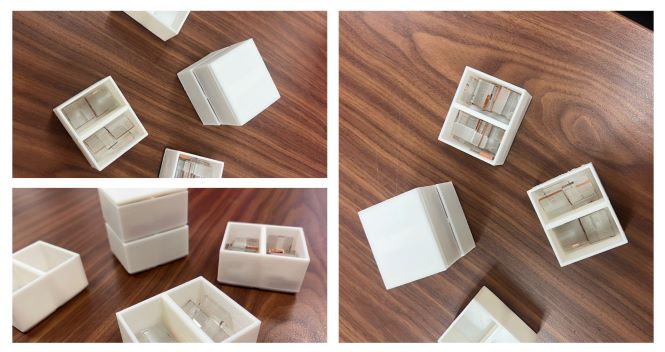
2- Puzzle pieces boxes
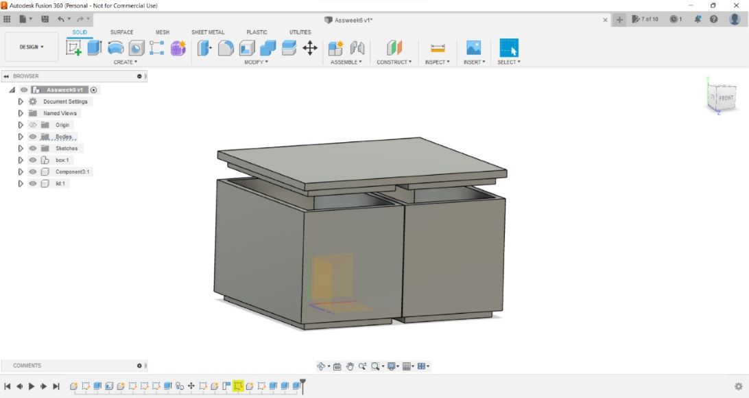
to make my puzzle easier I design 12 small boxes by numbers so that if the players want to start playing they can arrange the puzzle by lines depending on the puzzle box and print it on a 3D printer.
2- Puzzle pieces boxes
After I finish learning and practicing with a simple model now I will work on one of the 3D pieces I will use on my final project and because I finish my week assignment early I have a chance to use another 3D modeling program
final projectfinal project
One of my colleagues advised me to use the Onshape so I do a quick search about it
The feature of onshap:
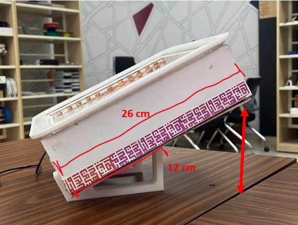
when I start the design I am worried about the right angles and the right height of the stand .my plan is to create the final project box with light material but I think it’s will still heavy because there are many sheets inside So I start to design it at 45 degrees and the height of the stand was half of the box hight.
The box height is 20 cm. The stand height is 12 cm with 45 degrees.
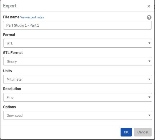
After I finish my design in Onshape I export it to an STL, Select all the objects then click right click, the menu shows up then click Export
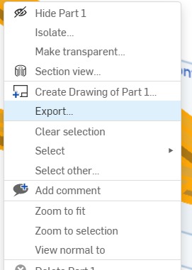
from here you can choose the format and units and there are different options
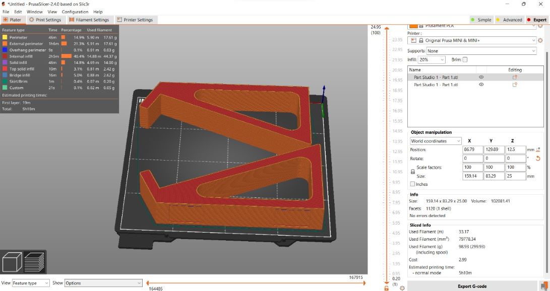
then I open the Prusa slicer to send it to the machine, Import the file and set it up
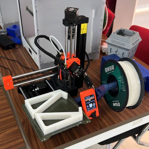
Print it
I extended the length of my old design in Onshape
, it became very long so I divided it into two pieces because I’m using Mini Prusa, so my design became oversized
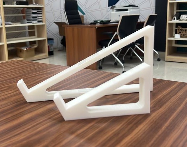
here after the print its finished
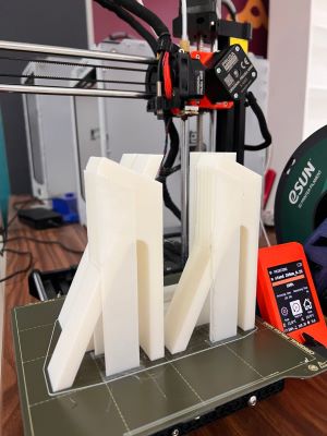
you can see the different sizes between the old and new stand
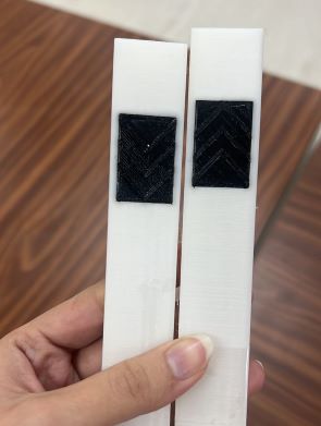
The final touch on my stand, I want to add rubber to be sure the stand is a stable , and in onshape I’m already designing a place for the rubber
here I print my small staple rectangle by using a black rubber filament (I borrow it from my colleagues)
Final Result
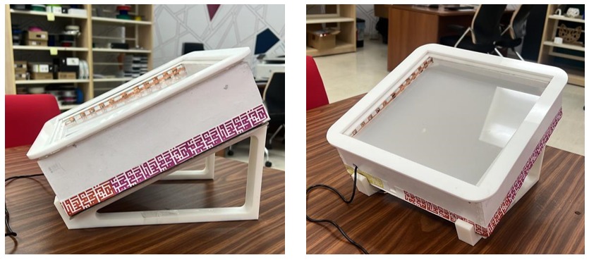
details check my 3D Scanning and printing assignment
BOM Of Fabrication part
| Qty | Description | Price | Link | Notes |
|---|---|---|---|---|
| 2 | Acrylic sheet Transparent | 60.00 SAR | https://signtrade.com | Semi-transparent |
| 1 | Acrylic sheet White | 30.00 SAR | https://signtrade.com | |
| 1 | PLYwood | 52.70 SAR | www.madar.com/ksa_ar | |
| 1 | MDF | 48.30 SAR | www.madar.com/ksa_ar | |
| 2 | wood glue | 129.75 SAR | https://www.saco.sa | |
| 1 | White spray | 17.50 SAR | Local Office Stationery | |
| 3 | Foam bored | 9.20 SAR | Local Office Stationery | |
| 1 | Copper tape 5 mm | 27.99 SAR | https://www.amazon.sa | |
| 2 | White Filament PLA | 300 SAR | Local Store https://maker.sa/ |
▶ Electronics design , production and Embedded programming
Addressable LED WS2812B
【 Now let’s start with electronic part 】

Because I want to create a lighting interactive playboard that matching with puzzle square grid I decide to use Addressable led strip ws2812b
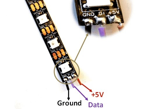
Addressable led strip WS2812B 3 Pins:
- 12V or 5V
- GND
- D0 ( Data )
Power Pin
Power Pins The power pin is simply a power input pin for the whole strip, most LED strips operate with 5V, or 12V or 24V power supply here I’m using 5V.
GND
The ground pins to make the common ground with all the controlling devices. In the whole LED strip, all the grounds are common with IC WS2812/SK6812. Further, the IC gives a single ground pin to make the common ground.
Data Pin
The data pin is for the Microcontroller/Arduino. It takes the serial data input from the Arduino/Microcontroller and then displays the LED pattern on the strip according to the given data.
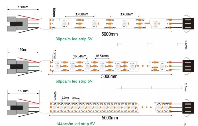
LED density this means how much LEDs the strip has per meter. You can find a wide variety of LED densities since 30, 60, 72 , 120 LEDs per meter and other options here I’m using IP66 (300 LED’s).
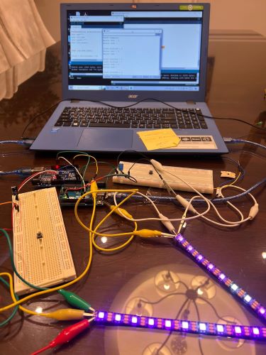
Let’s make an RGB Matrix using FastLed Liberary
Since this is my first time using Addressable LED I start a little practice to understand the coding and how The LED pixel work.
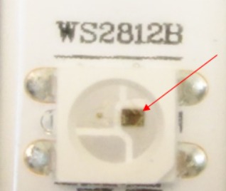
In digital LED strips as I have, you can control each LED individually ,The WS2812B LEDs have an IC built right into the LED.
FastLed Library
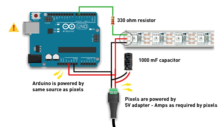
I download the FastLed Library github.com/s-marley/FastLED-basics and then I connect the LED with Arduino
PCB
Before designing My PCB, I have to list the numbers of input and output devices that I expected to use in my project I plan to use 12 LED strips with 12 Buttons pins so I decide to use an Two Atmega microcontrollers to be sure will turn on all the lines pixels very well with external 5V power.
-
Atmega328P components (For 1 board):
○ Crystal Resonator
○ ISP.
○ FTDI Male Header 6x1
○ 2*3x2 Header,
○ 1*2x2 Header.
○ 2*Resistor 10k.
○ capacitor.
○ Resistor 10k.
Schematic
To draw the schematic my plan is to create 12 LED Pins + 12 Touch buttons as I explain If the Copper parts in the puzzle will attach the LED strip will turn ON (Touchable buttons) So I will create 2 Atmega boards.
I will start with one and then copy it
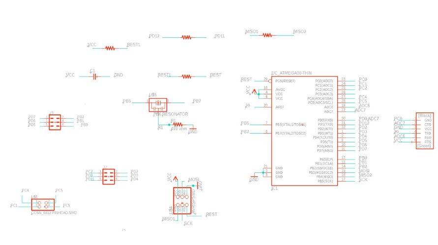
start adding the main components and then the headers I want to use all the pins in Atmega (28 pins) by following the datasheet
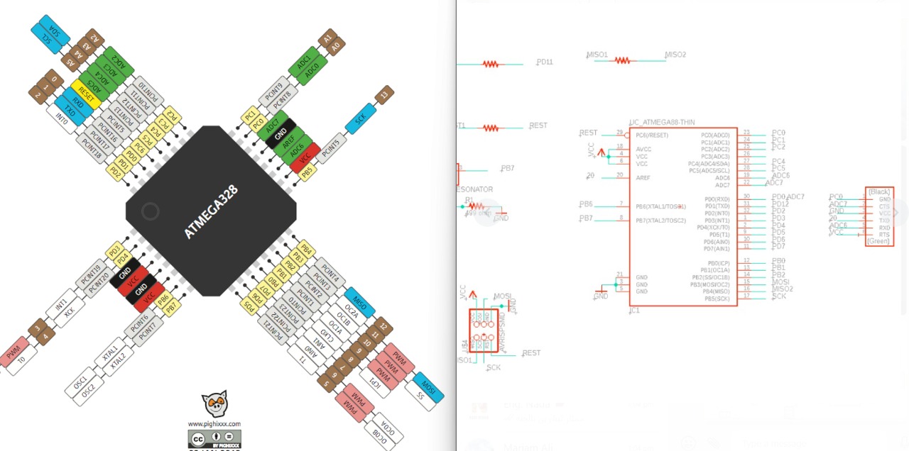
As I mentioned in the above I need 12 pins in one board in addition to VCC , GND and TX/RX so I open the Atmega datasheet to create my circuit
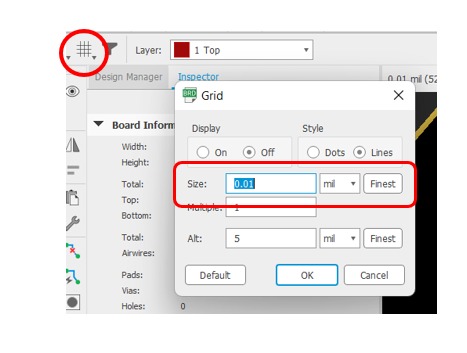
Before switching to the board and start drawing your wires be sure to make the grid 0.001to move easy
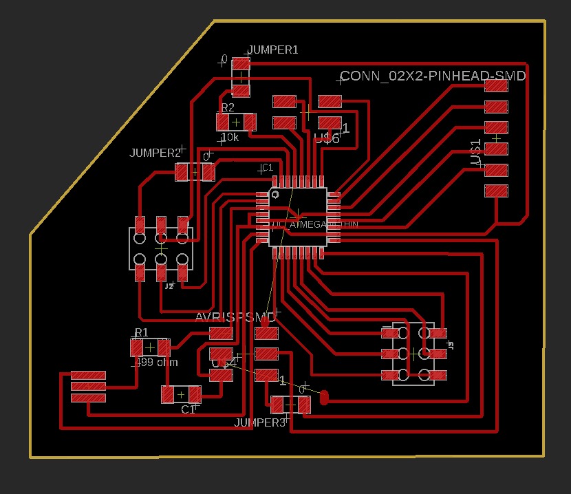
Jumpers
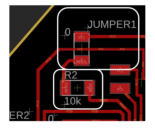
when I start to connect the wires It’s become very complex I decide to use jumpers so from the somatic I add (Fake Resistor.) because I the foot print to make wires pass through the middle then I named them Jumpers and give them 0 value so I can know when I start soldering where are the real Resistor
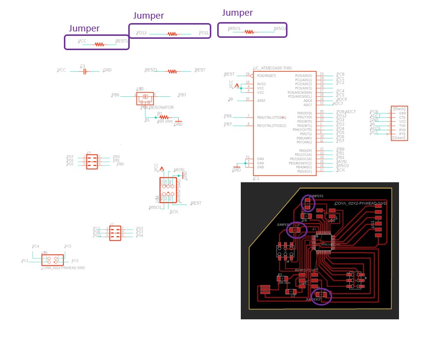
the name and value in the schematic
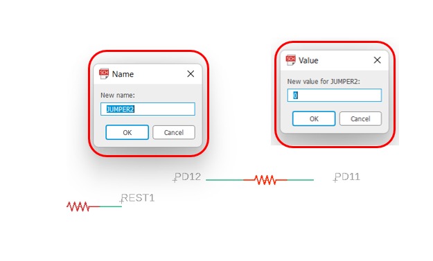
here are the name and values for jumpers and the Resistor
here I have another problem with wires but this time I can’t solve it by adding a fake Resistor I decide to use jumper wire so I draw a red wire and make it very thick to create a space to solder the normal wire
Export my schematic from eagle go to
File > Export > hide all layers . keep only Top layer
Now Open The MOD to start Mill my bored with milling machine
Trace >>
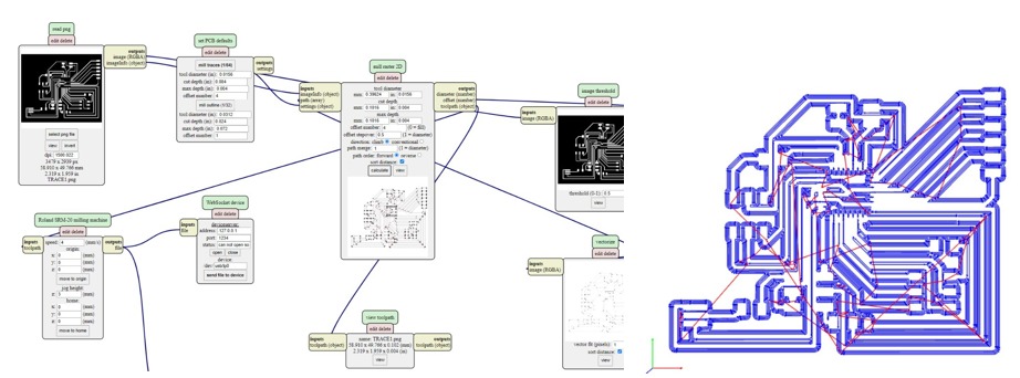
and for the Outline go to
File > Export > hide all layers . keep only Dimension layer
Outline >>
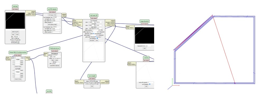
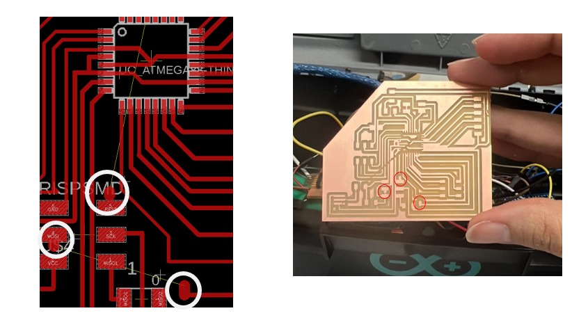
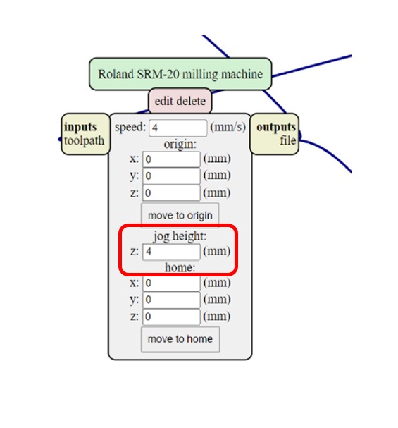
As you see in the picture if the machine finishing the work and the cutting tool in here way to go back to the 0 axises it is create a line destroyed everything
I try to fix the problem by changing the jog height to 4 mm
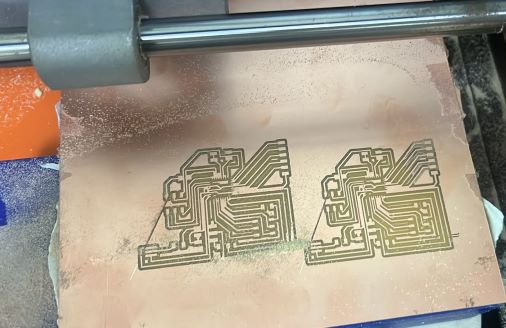
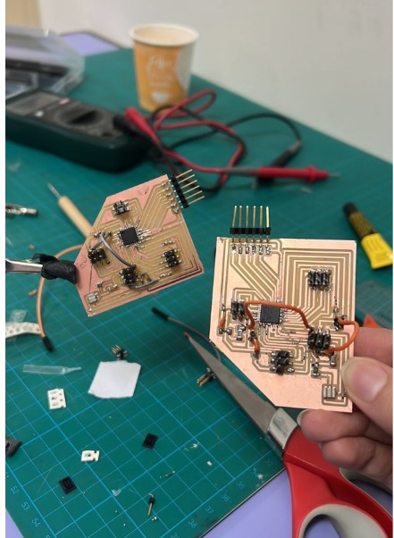
I repeat milling the boards they are better than before, there is a cutting line in some areas but I check by multimeter if the line is cut I create a solder bridge between

Soldering
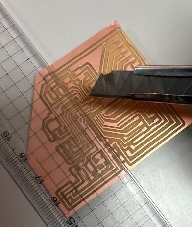
when I start solder I notice some uncut lines I use a ruler with a cutter ( I use always make a non-straight lines because this I use ruler)
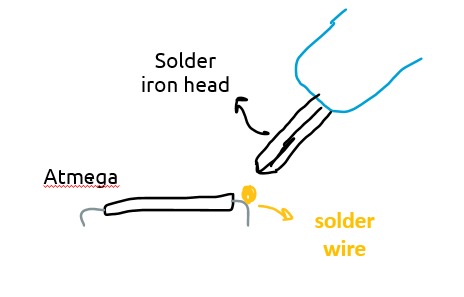
Atmega have very tiny pins and they are very close to each other, making the soldering is a big challenge I start sticking the atmega by using double stick tape then by using a high degree iron solder I mel a very small amount of soldering wire and make it in the top of atmega pin then take the iron head focus it to the solder wire in the top and leave it there until you see the solder melt and cove the pin
Connection & Code
In this part, I will explain how the connection will go, as I explain in above I will use 2 ATmega boards (Master & Slave) first board will respond with about 6 LEDs and Buttons then after this flow finish the serial will send to the Slave to complete the several works which are the second 6 LED’s and buttons and in the end the total will be 12 LED’s with 12 touch buttons I start this code from scratch with my instructore and this is my first time to create like this huge code I’m very stress full but very great full to learn.
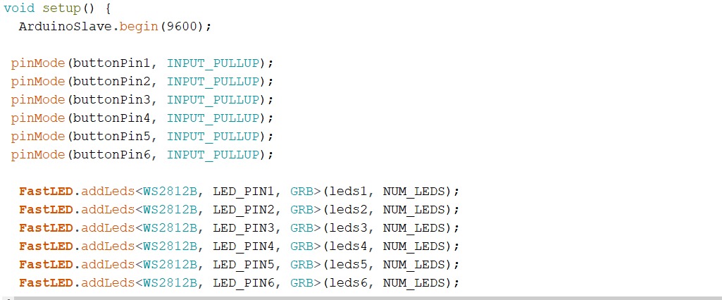
With my instructor, we start to define the pins we will use and set our plan for how will the project work so to understand better we start work in Arduino we start to set the pins we will use for each board
Explain the code and pins on Arduino
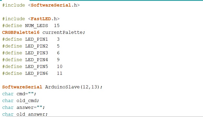
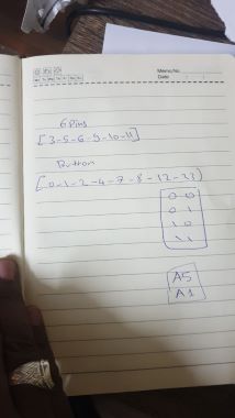
let’s start with the master board in the beginning we need to include the libraries we will use and the numbers of LEDs in each line then we define the led pins
6 pins in Arduino connect it to the data LED pins (3 / 5 / 6 / 9 / 10 / 11)
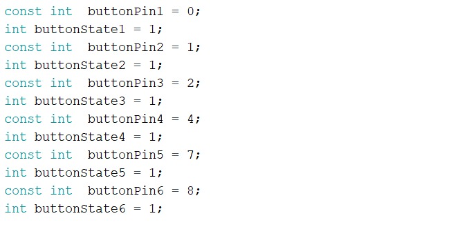
Now we start to define the Button pins and the value will start with 1 (Input pull-up button)
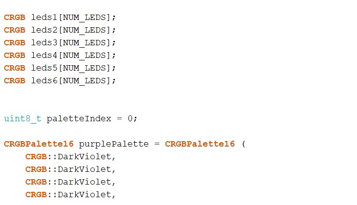
here we start to define the color of the LED Strips I used this is the most important part for me I want it to be a gradient in violet colors and thanks gad it happen in the beginning it was only green but my instructor searched for the right code and then find it because if this we decide to use two ATtmega to be sure that will be work good

then here black means when the LED is turned OFF so if you connect the power it’s Black (OFF) until we send a message to turn the color (ON)
now let’s start with the serial first write the buttons and LED (what kind of LED and buttons We used, the name of them and the pins will data send and receive), then explain to Arduino when moving to other board which is the slave to define this we list the numbers of LED and buttons.

cmd it’s a variable means here the message will send to the button to keep the LED ON (in here old status) and keep it in the same status until all 6 LED open then move to the Slave board to complete work.
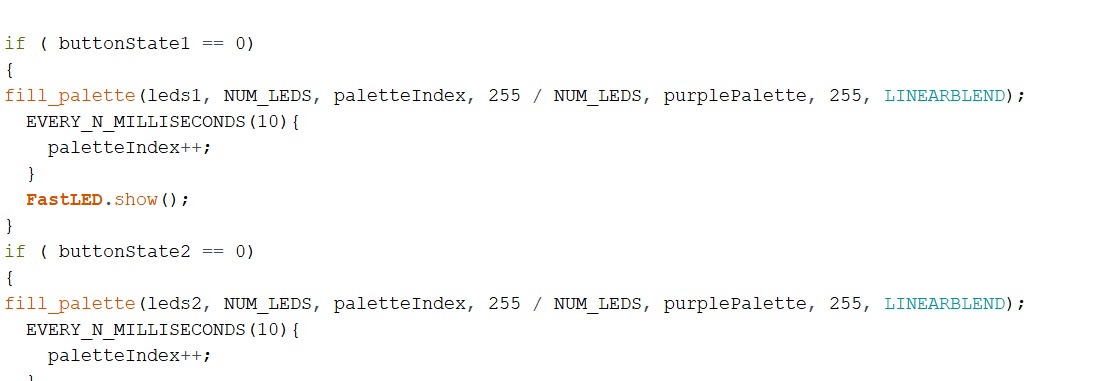
in If statement the code tells the master board If the button is pushed ( here I mean touched with puzzles that are covered with copper) the button status will change to 0 value which means the LED Strip will turn ON with the color palette we already define in the top.
and we repeat these lines until we cover all the first six LED lines
if ( buttonState1 == 0)
{
fill_palette(leds1, NUM_LEDS, paletteIndex, 255 / NUM_LEDS, purplePalette, 255, LINEARBLEND);
  EVERY_N_MILLISECONDS(10){
    paletteIndex++;
  }
  FastLED.show();
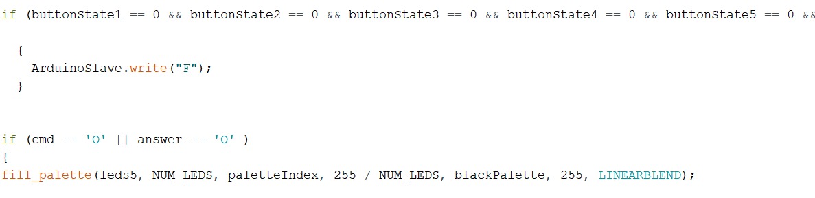
in the end, explain the message send and receive so if the buttonstate == 0 until buttonstate == 0 that means all the first 6 LED strips are already open and make the action now the data will move to the other board (Slave Board ) and do the same master did.
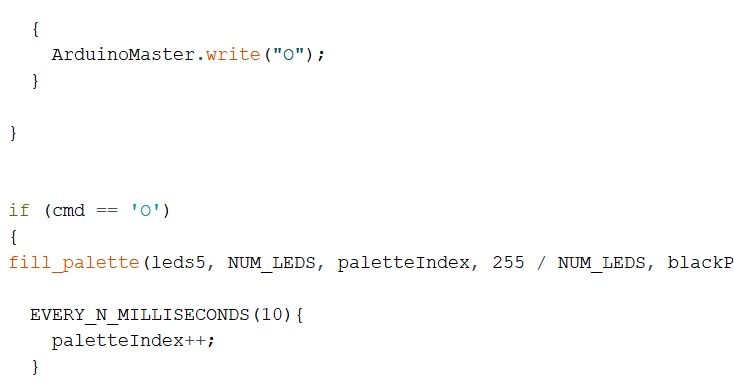
In the slave board is almost the same as the master board the change is the message received from the master board to start work.
Connection
Now I reflect my work from Arduino pins to my Atmega Pins, Start opening the Atmega data sheet and select my pins as I mentioned above we start practice with Arduino, now I will select the Atmega pins by following the Arduino pins that we used when we practice.
For LED [PD1 - PD5 - PD6 - PB1 - PB2 - PB3 ] I used IN atmega as outpin ,for the buttons I used [PD0 - PD1 - PDPD2 - PD4 - PD7 - PB0 ] as input pins , then TX/RX = [PB4 - PB5] THEN I power my boards by 5V power supply.
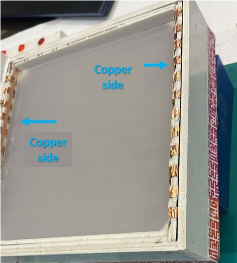
the buttons will work like normal buttons but here I don’t have two legs connected with two wires I have two copper sides (the legs) and when all puzzles are complete the circuit will complete then the led strip will turn ON .
like I said above by using solder I connect one side of the copper tape with GND and another side with ATmega pins, for the button I used [[ PD0 - PD1 - PD2 - PD7 - PB0 ]]* As input pins.
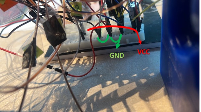
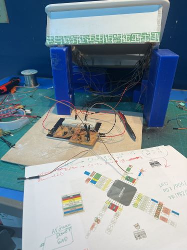
for the power, I order a 5V power supply then I cut it, and connect it with Male headers by solder then connect it with the 100uf capacitor and I used jumpers to make the connection with the 2 boards the I use jumpers to connect with other wires ((I’m using the Breadboard only to power my two boards)).
I label my wires by numbers and colors to connect them correctly and help to know which wire this one for when I face the problem
in the end, I used a small foam board and stick all my boards on it and use a glue gun to be sure there are no wires that will move, and close my box, I was very worried about the spaces between each panel especially this one with wires but thanks gad it is fit well ,no wire move and it’s enough for all ☺.
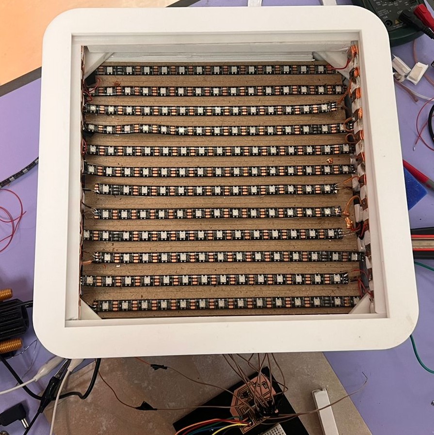
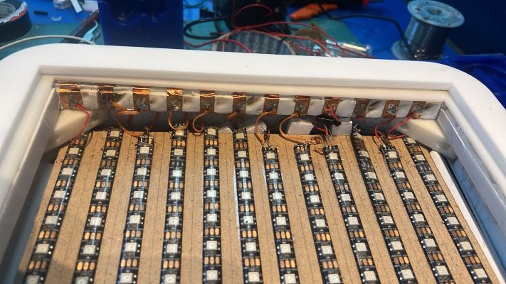
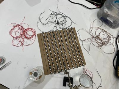
LED Panel
I create my measurements depending on my puzzle grid between each line 2 cm to make the LED line in the middle of each puzzle line, I draw my lines then I stick my LED strips, the LED strips have glue sticker on the back but because I use MDF wood sheet the dust of the MDF did not allow the led strips stick very good, so I add another double stick tape
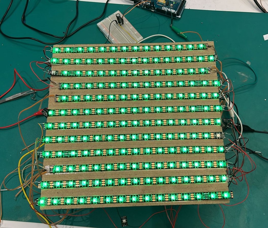
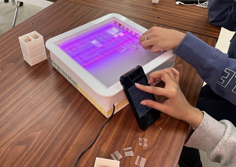
How Its works
how my project will work, the LED Strip will work line by line I have 12 lines with 12 LED strips and each LED line connect with Button so if the players arrange the puzzle pieces that cover with copper tape in good order and all the pieces attach very well together it will conduct the electricity (work as touch buttons) and the LED line will ON.
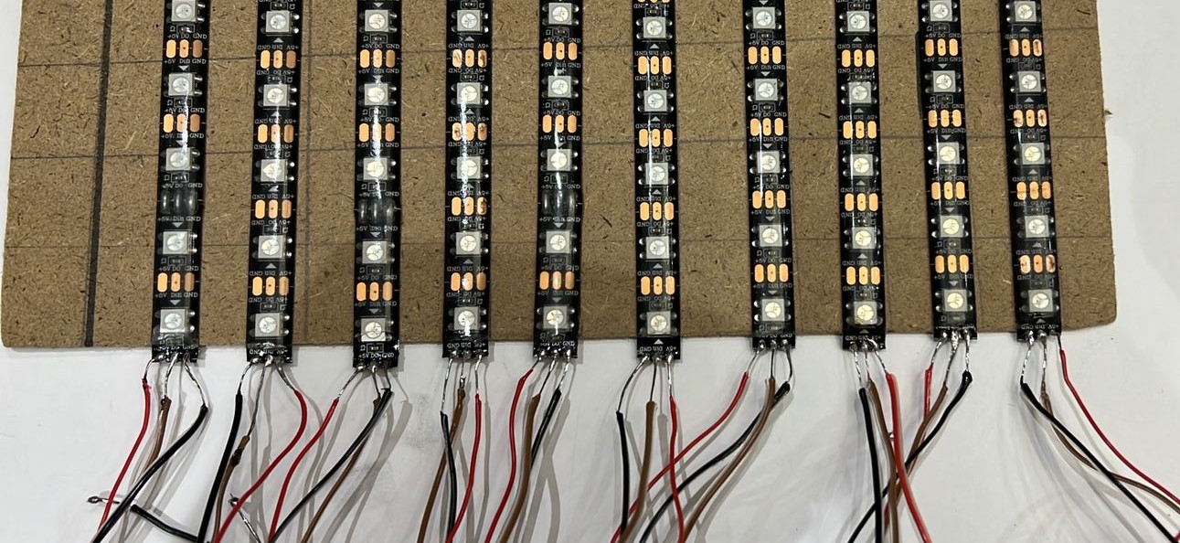
start soldering the LED Strips and it was very hard takes around 5 hours. On one side I have 3 wires GND, Data wire, and the volt wire in the other side I have only one wire which is the volt wire only
I connect one side with a 5V external power supply and on the other side, I connect with the LED Strip if the puzzle pieces are covered with copper tape connected to another they will conduct the electricity to the other side so the LED line will turn ON.
Testing the LED strips
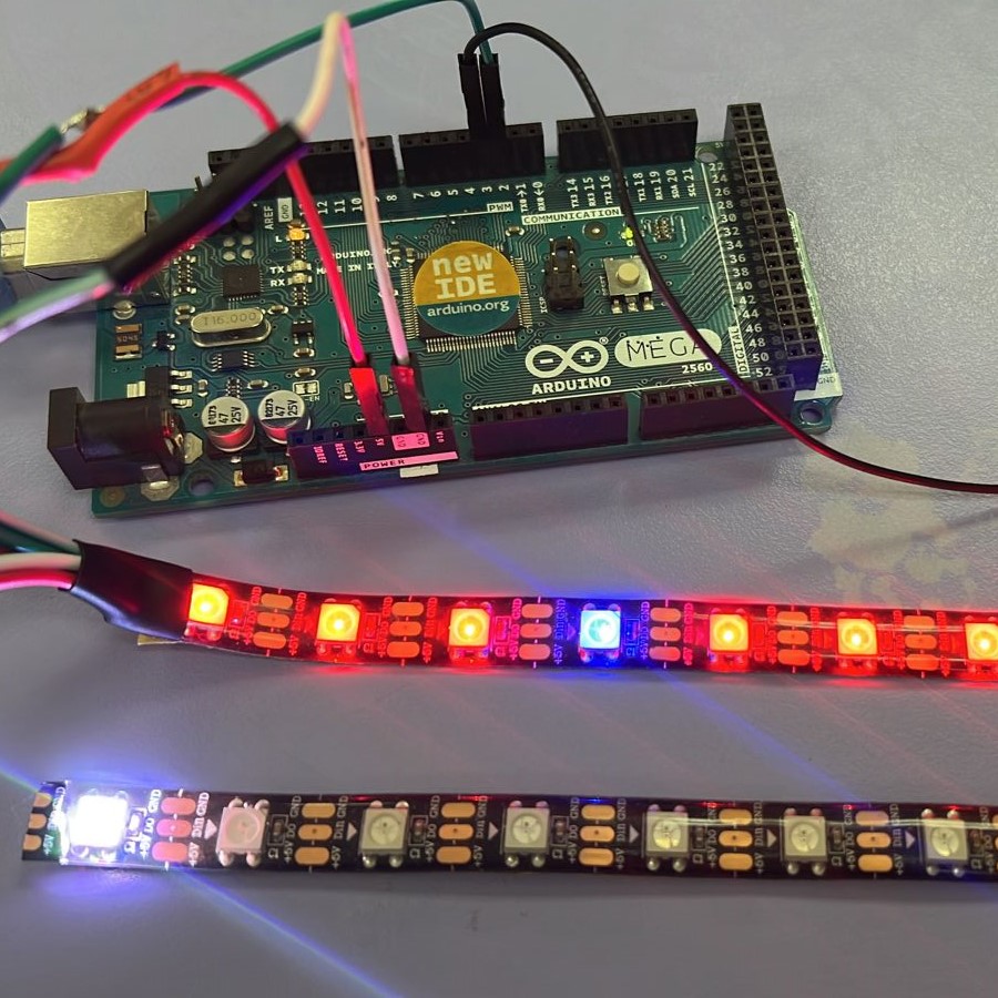
this is my first time working with addressable LED I note that each time I turn on the led and send some coding I face problems like one LED just turning on and sometimes one pixel LED turns on by different color, I search and ask about how I can fix this problem to fix it I need to add a capacitor with GND and VCC OR I can add resistor with each data pin for me I add capacitor with GND and VCC and after all every single LED working very well without any problems.

Another problem I face with addressable LED is the data pin direction there is a small arrow in the strip that means the data will start with this direction if you send the code by the number it will start with the arrow discretion
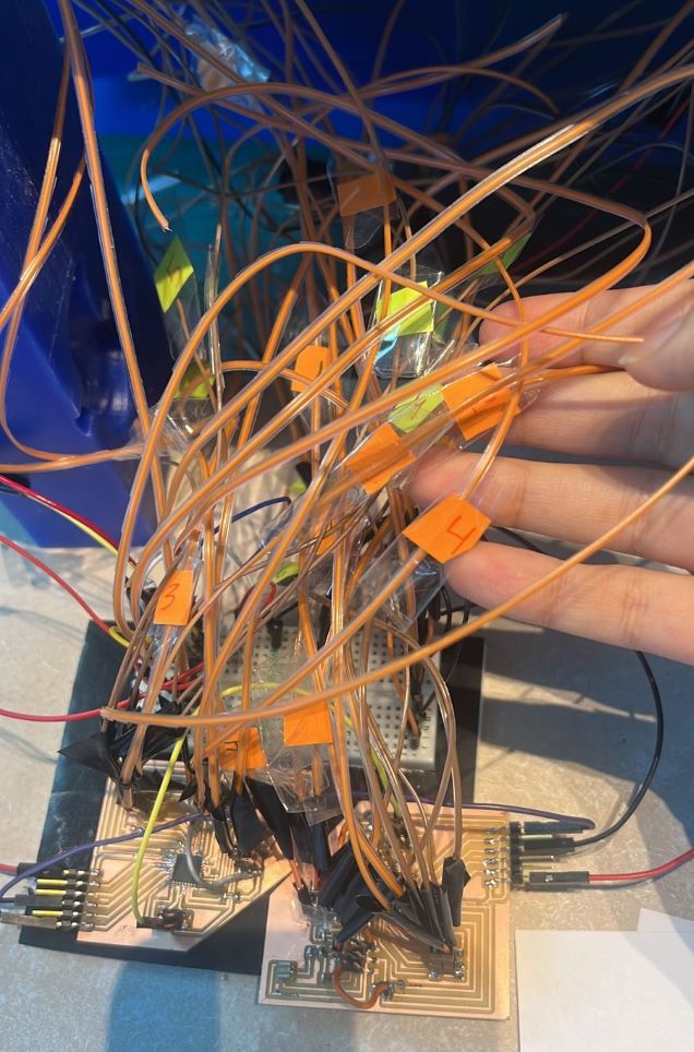
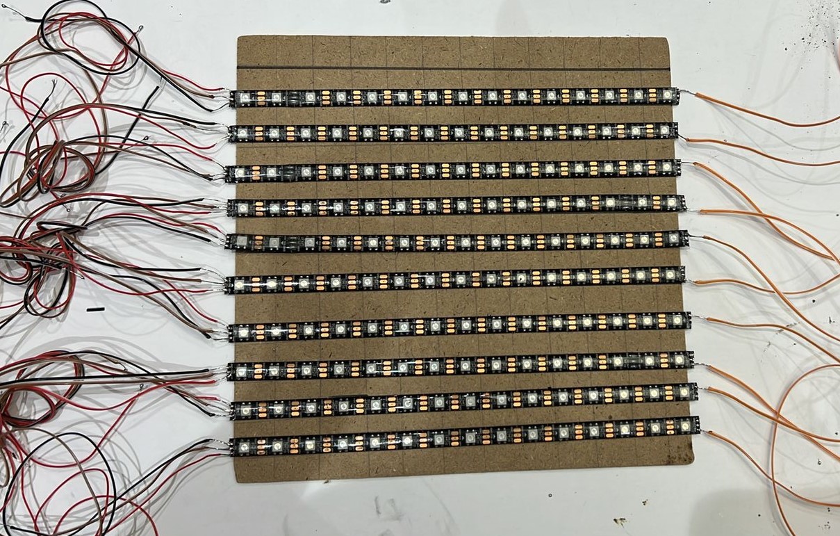
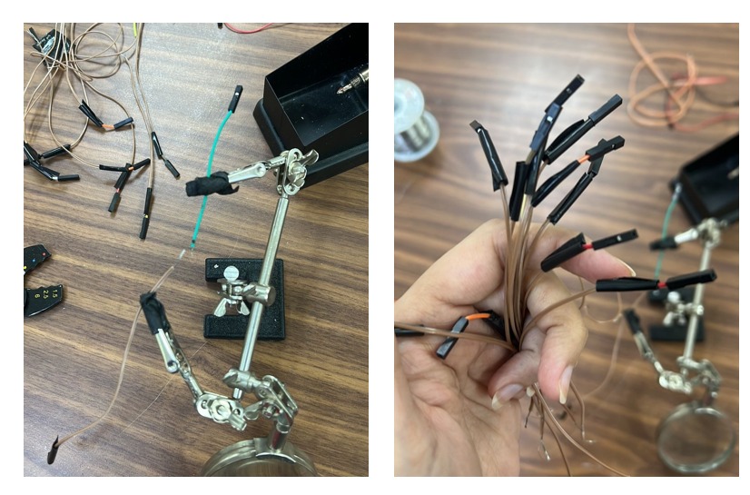
Prepare my wires
I create my wires by myself I cut them and divided them into 3 categories the RED wires for the power the black wires for the Ground then the orange wires for data pins
On one side I solder it with the LED strips the other side I solder it with male headers (to be honest it was very hard work and I’m losing materials because I cut too many male-to-male jumpers) , I add electronic tape around the soldering headers to be sure its fix and there is no electronic transformer.
Arrange the Panel sheet
I do a mark on the sheet to stick the LED In Lines.

BOM Of Electronics part
| Qty | Description | Price | Link | Notes |
|---|---|---|---|---|
| 1 | Addressable LED Strip WS2812B RGB 300 LED | 118.59 SAR | https://www.amazon.sa | |
| 1 | Plug Power Supply AC 100-240V to DC 5V | 36.00 SAR | https://www.amazon.sa | |
| 1 | Adapter Connector | 19.00 SAR | https://www.amazon.sa | |
| 1 | Heat Shrink Tubing | 30.00 SAR | https://www.amazon.sa | |
| 5 | Single Side Copper Clad | 24.75 SAR | Electronic Waves | 100x150x0.8mm |
▶ Slide & Vedio
Final Result
-
Final Vedio
Final Slide
▶ The License

This work is licensed under a Creative Commons Attribution-NonCommercial-ShareAlike 4.0 International License.