9. Embedded programming
▶ Individual assignment:
- Read the datasheet for your microcontroller.
- Use your programmer to program your board to do something.
● Introduction
In WEEK7 assignment I had my broken down so I read and learned a lot of information about electronic circuits, here I will summarize my information and focus on what we need in this week
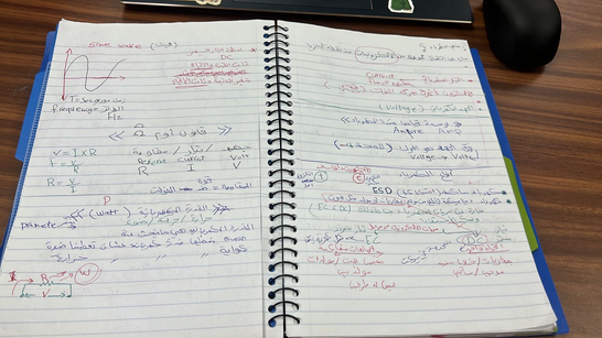
Electronic Circuit components:
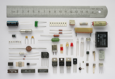
- Capacitor.
- Resistor.
- Diode.
- Transistor.
- Inductor.
- Relay.
- Resonator.
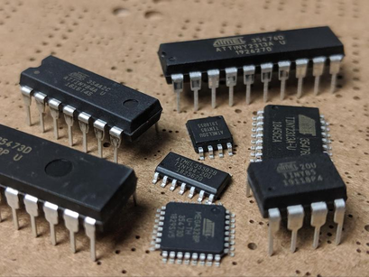
● Integrated Circuits (ICs):

Jack Kilby invented the first integrated circuit in 1958 at Texas Instruments The sole purpose of ICs is to increase the efficiency of electronic devices while reducing their size and manufacturing costs.
What is (ICs):
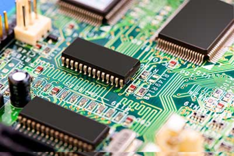
They are tiny electronic circuits that can fit inside a small silicon chip. Though PCBs can offer a lot of advantages, most modern instruments such as computers and mobiles require complex circuits, having thousands and even millions of components. That’s where integrated circuits come in.
Classification of ICs (Integrated Circuits):
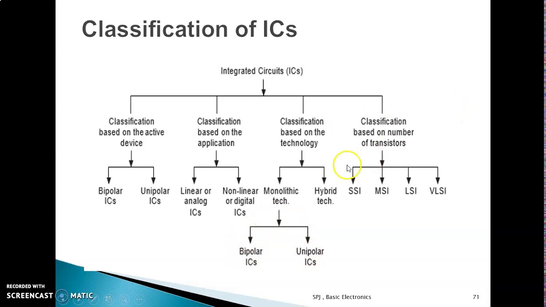
- SSI: Small scale integration. 3 – 30 gates per chip.
- MSI: Medium scale integration. 30 – 300 gates per chip.
- LSI: Large scale integration. 300 – 3,000 gates per chip.
- VLSI: Very large scale integration. More than 3,000 gates per chip.
Types of ICs (Integrated Circuits):
Based on the method or techniques used in manufacturing them, types of ICs can be divided into three classes:
- Thin and thick film ICs.
- Monolithic ICs.
- Hybrid or multichip ICs.
● Datasheet
ATtiny microcontroller:
ATtiny (also known as TinyAVR) are a subfamily of the popular 8-bit AVR microcontrollers, which typically has fewer features, fewer I/O pins, and less memory than other AVR series chips. The first members of this family were released in 1999 by Atmel.
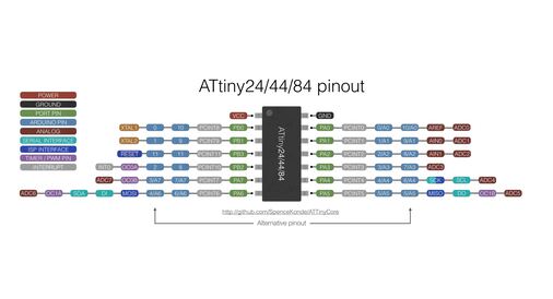
I’m using ATtiny44:
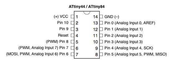
The ATtinny44 is a low-power CMOS 8-bit microcontroller with two Ports (A and B) based on the AVR enhanced RISC architecture. The two layouts above show the Ports on the ATtinny44 and their correspondence for the Arduino Environment.
PORTS SUMMARY(for Board Layout):
- RX: Recieve Data on PA0/Pin 0 (*goes to TX in FTDI cable).
- TX: Transmit Data from PA1/Pin 1 (*goes to RX in FTDI cable).
-
Serial Peripheral Interface (SPI): Synchronous serial data protocol used by microcontrollers for communicating with one or more peripheral devices quickly over short distances. It can also be used for communication between two microcontrollers. With an SPI connection, there is always one master device (usually a microcontroller) that controls the peripheral devices.
-
Typically there are three lines common to all the devices:
✷ MISO (Master In Slave Out): Slave line for sending data to the Master.
✷ MOSI (Master Out Slave In): Master line for sending data to the Slave.
✷ SCK: Clock pulses to synchronize data transmission generated by the master.
- RESET: External active low signal resets the microcontroller.
Useful links
-
Electronic Components Datasheet Search ATTINY44 Datasheet, PDF.
-
make a linear position sensor fab.cba.mit.edu.
-
ELECTRICAL TECHNOLOGY electricaltechnology.org.
-
How Electronic Components Work blog.mide.com.
-
Digital Integrated Circuits: Definition, Types & Examples study.com/academy.
● Embedded Programming with Arduino
I work with my ATTiny44 hello world bored the one I manufactured in Electronic design Assignment week 07.
- The Arduino Software (IDE) allows you to write programs and upload them to your board.to Install the Arduino Desktop IDE >> download Arduino IDE.
- After Install The Arduino Software (IDE) Adding ATtiny Support to Arduino IDE because and By default Arduino IDE doesn’t support ATtiny so we should add ATtiny boards to Arduino IDE.
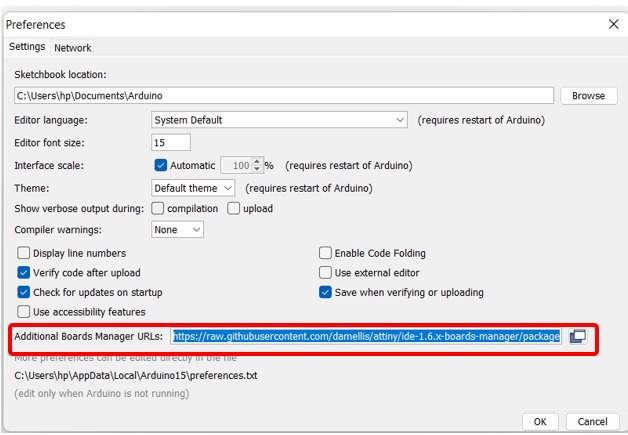
Open File -> Preferences
and in the Additional Boards Manager URLs give this URL https://raw.githubusercontent.com/damellis/attiny/ide-1.6.x-boards-manager/package_damellis_attiny_index.json.
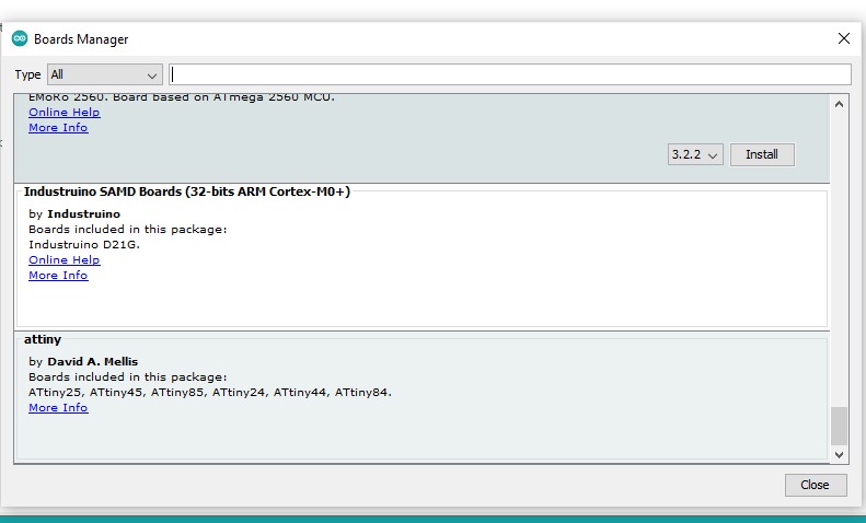
Now go to Tools –> Board–> Boards Manager, A new tab will open and at the top of the tab search for attiny and click Install you need to Restart the Arduino IDE.
- After done with adding bored
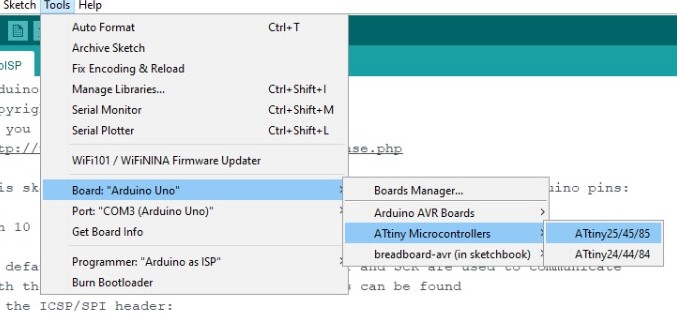
open Tools -> Board -> Board Manager
After installing now you would be able to see a new ATtiny Boards in the Board menu.
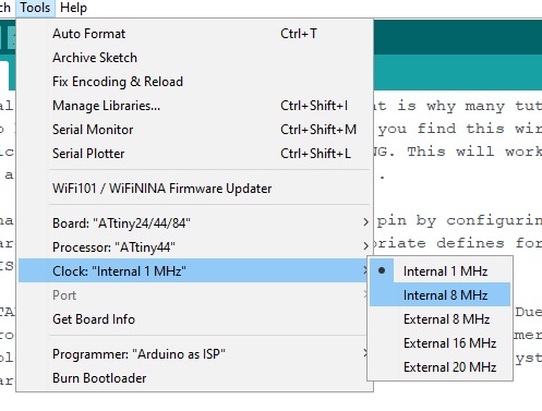
- Then Tools -> Processor. And select 8 MHz (internal) under Tools -> Clock.
- Configuring Arduino Uno as a ISP (In-System Programming)
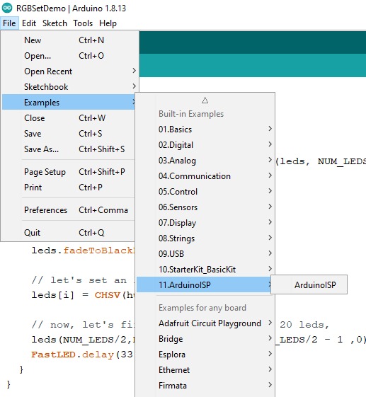
set Arduino Uno in ISP mode from
file -> Examples -> ArduinoISP
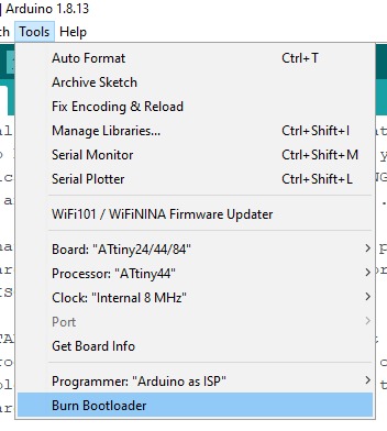
- By default the ATtiny runs at 1MHz. To make it to run at 8MHz select
Tools -> Burn Bootloader.
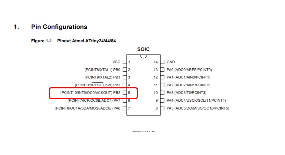
How a Microcontrollers Pins Are Label?
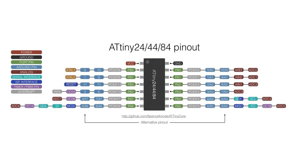
Before the connections are made we need to know how pins on microcontroller/ICs are labeled,Pin numbers used to program a chip on the Arduino IDE are based on how the chip manufacturer has internally named/arranged the pins here I will explain more with ATtiny44 because I will use it in this assignment.
Writing a program to light an LED on pin 5 on the ATtiny44 might be confusing at first because just by looking at the chip, there is no pin 5, However, by checking the datasheet of the ATtiny44 DATASHEET page 3 shown above-pin 5 is internally located on the chip’s port PB2 (and is actually the chip’s physical (I mean on Arduino pins) pin 8 OR 2 ).
Connecting the Arduino to the ATtiny Pins
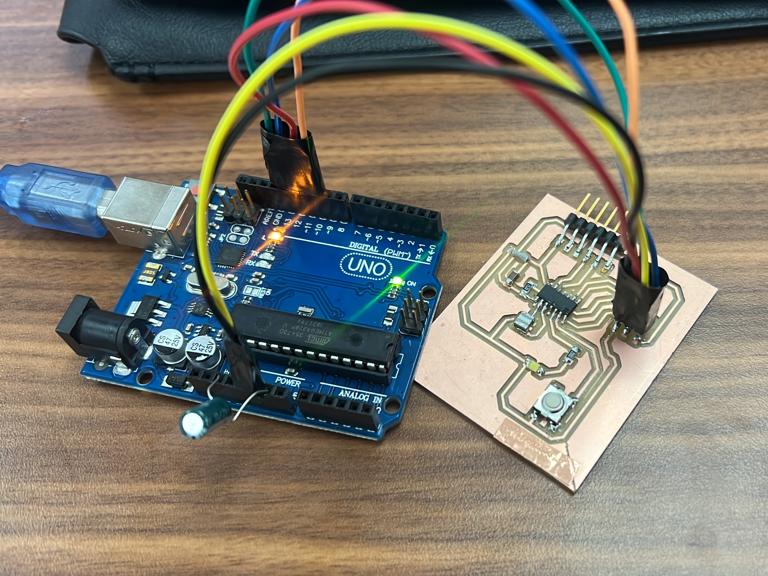
Use a jumper wires to make the connections bellow from the Arduino Uno to the ATtiny44
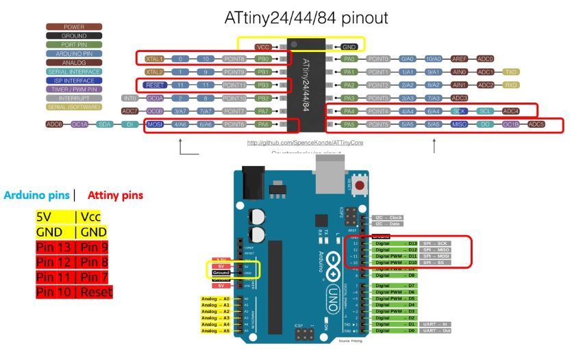
You can connect the Arduino pins with ATtiny pins By following the ATtiny44 datasheet for GND and VCC wires it’s easy to connect it to the GND pin and 5V pin on Arduino.
Arduino–> ATtiny44
5V | Vcc
GND | GND
Pin 13 | Pin 9
Pin 12 | Pin 8
Pin 11 | Pin 7
Pin 10 | Pin 4
The Code
// the setup function runs once when you press reset or power the board
void setup() {
  // initialize digital pin LED_BUILTIN as an output.
  pinMode(8, OUTPUT);
}

// the loop function runs over and over again forever
void loop() {
  digitalWrite(8, HIGH);   // turn the LED on (HIGH is the voltage level)
  delay(1000);                       // wait for a second
  digitalWrite(8, LOW);    // turn the LED off by making the voltage LOW
  delay(1000);                       // wait for a second
}
Final Result
● FABISP AND ARDUINO IDE
- Use your programmer to program your board to do something
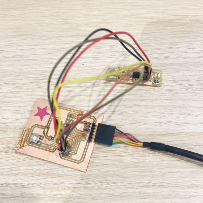
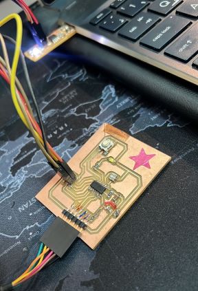
I’m using my FAB ISP the one I manufactured and programmed it through the Arduino in Electronic production Assignment week05 connect it with my ATTiny44 hollow word bored the one I manufactured in Electronic design Assignment week07
Connection
Connect the Fab ISB to the ATTiny44 board
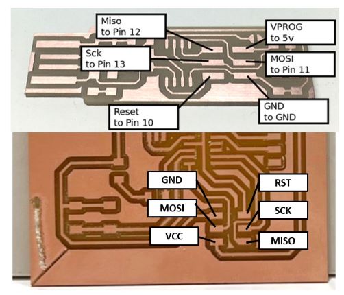
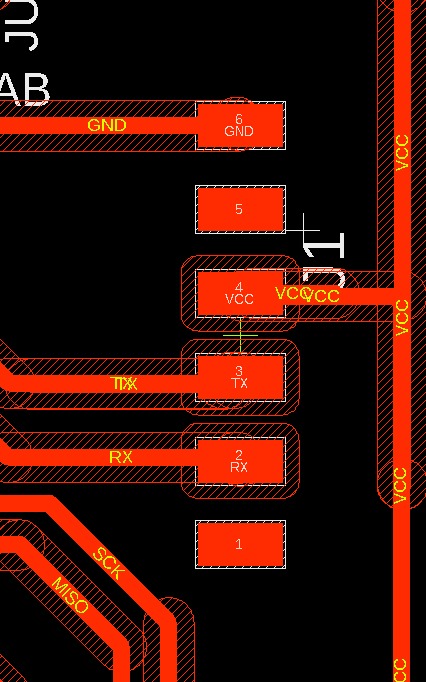
to do my connection I open my schematic then I create this design to follow the drawings and connect the right pins
FAB ISP –> ATtiny44
Vcc –> Vcc
GND –> GND
MISO –> MISO
MOSI –> MOSI
SCK –> SCK
RST –> RST
FTDI Cable
Now Connect the FTDI Cable to the FTDI header in ATTiny44 board
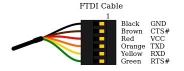
we connect the FTDI cable depending on the diagram above So I open my schematic to follow the pins
be sure that the Black wire (GND) is on top and the Green wire (RTS) is on the bottom when connecting it to the ATtiny44 board depending on my schematic
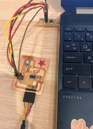
Now Connect the FABISB to My computer then the FTDI cable to another USB for power
Programming with Arduino
open Arduino IDE and follow the same steps in the above I will go through it quick
first need to install the ATtiny support manager for Arduino
Open File -> Preferences
and in the Additional Boards Manager URLs give this URL https://raw.githubusercontent.com/damellis/attiny/ide-1.6.x-boards-manager/package_damellis_attiny_index.json.
Now go to Tools –> Board–> Boards Manager, A new tab will open and at the top of the tab search for attiny and click Install you need to Restart the Arduino IDE.
- After done with adding bored
open Tools -> Board -> Board Manager
After installing now you would be able to see a new ATtiny Boards in the Board menu.
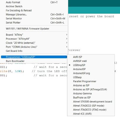
- Then Tools -> Processor. And select “20 MHz (External)” from Tools > Clock.)
- Then select Tools > Programmer > USBTiny
file -> Examples -> USBTiny
Now Check if the FabISP is recognized
To Check if your FabISP is recognized in your computer you need to plug it into the USB drive and the message will show up directly
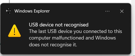
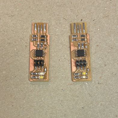
as you see it does not recognize So I keep thinking and checking what the problem is until I Remember the I create 2 ISP I bring the good one and complete my work (Such a relief)
Now I plug the right FabISP there is no message show up put the LED turn ON that mean its work I Connect everything and upload my Code
#define LedPin 8
#define SwitchPin 3


void setup() {
  pinMode(3,INPUT);
  pinMode(8,OUTPUT);

}

void loop() {
  boolean switchState;
  switchState=digitalRead(SwitchPin);

  if(switchState == 1){
    digitalWrite(8,HIGH);
  }
  else{
    digitalWrite(8,LOW);
  }
}
Final Result
● Embedded Programming with C
Because I’m always using Arduino IDE to program, it’s the first and only programmer I learned and used I was interested to learn more about the Programming language.
What is C language ?
C is an imperative procedural language supporting structured programming, lexical variable scope, and recursion, with a static type system. It was designed to be compiled to provide low-level access to memory and language constructs that map efficiently to machine instructions, all with minimal runtime support.
History of C Language
C programming language was developed in 1972 by Dennis Ritchie at bell laboratories of AT&T (American Telephone & Telegraph), located in the U.S.A.
Dennis Ritchie is known as the founder of the c language. It was developed to overcome the problems of previous languages such as B, BCPL, etc.
What is the difference between C and Arduino Sketch?
To get machines to work like how you imagine them to, you need to program them to work that way. This programming was initially mechanical linkages, then with electronics; logic signals. Later assembly language, B and finally Dennis Ritchie made C (1972). Even though it was made so long ago, it was so well done that it is used even today.
Evolution of the tools to make machines do what u want them to.
But people wanted to do more, Obviously. So a lot of other simpler-to-understand languages came out.
But the point here is your C code breaks down to assembly code which becomes logic signals and the DC motor is rotated with the mechanical linkages and gears. Encapsulation!
Arduino is a layer more, they have so many C-like functions/APIs placed in a library. Instead of writing the whole C code. Use these APIs to make your machine do what you want it to. There is also a scheduler that makes that main function of your C simple to comprehend as a setup function and loop. You can initialize things in setup and keep a repetitive action in a loop.
That’s the Arduino sketch, the next layer of encapsulation is graphical drag and drop programming for kids. This puts the Arduino APIs which finally end up rotating that motor via gears.
- I find this answer In ( https://www.quora.com ) and It was very interesting information.
C code Arduino IDE
I look for other Examples to test a blink LED code in C using Arduino IDE because I had zero experience with C and I think its would be difficult to try to C code from scratch So I follow Program Arduino Uno in C Language.
Lets Start

Firs we need a software To write code in C, Here will use Code Blocks Download ,a light weight, easy to use and it has a built in software to directly upload the code to your Arduino.
After download it Unzip the file and open the software
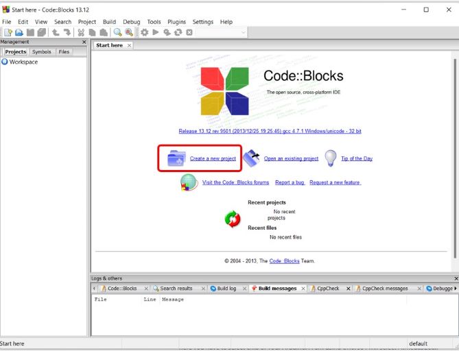
To create new project click > new project from the front page.
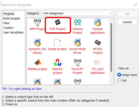
the window will showup Select AVR project then click Go >> Click Next give name for your Project.
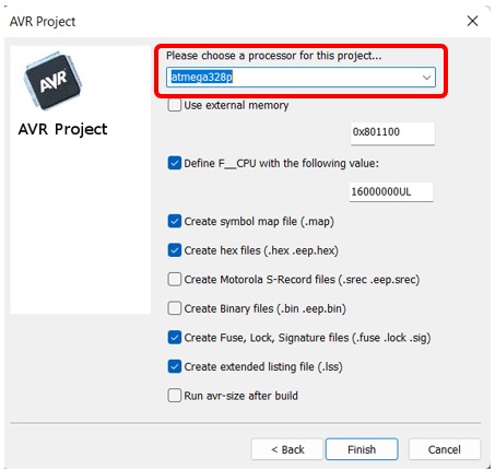
here important step Select chip of your Arduino, ( I’m using Arduino Uno, so I select Atmega328p) and then click finish.
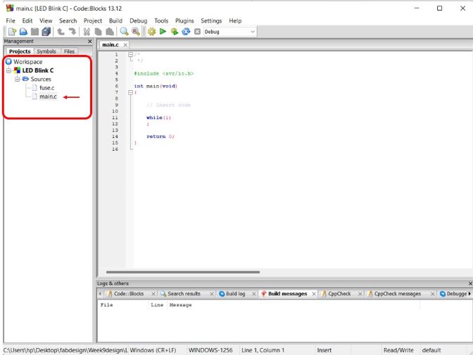
On the left side Click work space Double click on >> sources >> select main.c.
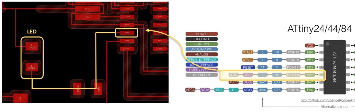
Be sure to type in “PB5” it is the port my LED connect with in ATTINY44 as the shown picture in above
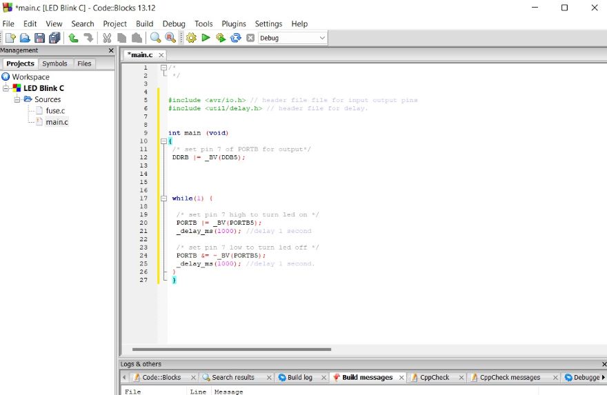
We set every things now copy the code in below and past it on the blank space.
/*
 */

#include <avr/io.h>
#include <util/delay.h>

int main(void)
{
    DDRB |= (1<<PB5);//SET LED PB5 as an output
    while(1)
        {
        PORTB |= (1 << PB5);//Turns LED on
        _delay_ms(1000);// Delay for 1 sec
        PORTB &= ~(1 << PB5);// Turns LED off
        _delay_ms(1000);/// Delay for 1 sec

    }
    ;
    return 0;
}
Code Explanation
Here the simple code of the C language
we use this code to send to the chip where all the ports & pins are located.
this means that actual time values can be specified rather than a number of cycles to wait for.
DDRB
DDRB is the Data Direction Register for port “B” if you set this register, all ports or pins in the “B” I/O port act as outputs
PORTB5 In Uno
when the ports or pins in the “B” I/O port act as inputs.
BV
bit value.
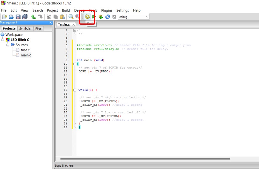
Mow Click on the Run (The gear icon) It’s will compile and build all the necessary files.
Arduino Builder
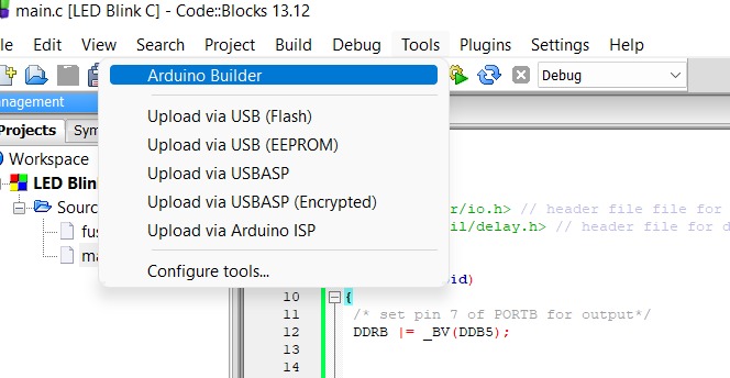
Now Click tools >> Arduino Builder.
Now we will Uploading Code to Arduino after click Arduino Builder the A program will open, in this step you should plug your Arduino.
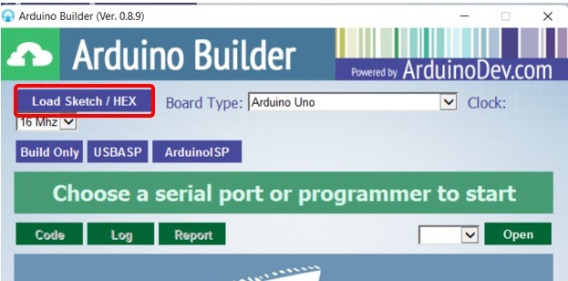
Click Load sketch/HEX
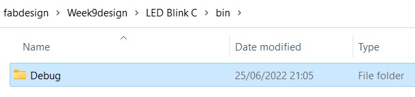
Save the HEX file with in the same place of the Code Blocks file code. here > in C drive/file_name/bin/debug/.
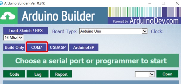
as soon you click on the COM port, the Arduino Builder will start to program it the problem here is the Arduino port doesn’t show up I plug it and unplug it several times but it does not show up So I decide to change the Arduino UNO and YES It’s here now.
Final Result
Files
▶ Group assignment ✌
- Compare the performance and development workflows for other architectures