15. interface and application programming
▶ Individual assignment
- Write an application that interfaces a user with an input and/or output device that you made.
>Processing software
![]()
Here I’m starting with processing software
![]()
Processing software is a free graphical library and integrated development environment (IDE) built for the electronic arts, new media art, and visual design communities with the purpose of teaching non-programmers the fundamentals of computer programming in a visual context.
![]()
I downloaded the software and start with a tutorial on the website
![]()
Lets Start
after you download it Unzip the folder and Click the processing application then this window will showup
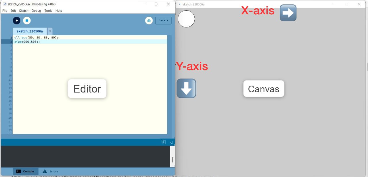
Editor
the large area is the Text Editor, and there’s a row of buttons across the top; this is the toolbar. Below the editor is the Message Area, and below that is the Console. The Message Area is used for one line messages, and the Console is used for more technical details.
Canvas
The canvas is a two-dimensional grid. The coordinate (0, 0) is at the upper-left corner of the canvas.
●Draw
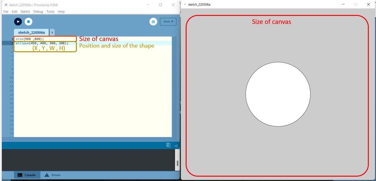
Start with an instruction to draw Ellipse the instruction is start with
size(900 ,800);
ellipse(450, 400, 300, 300);
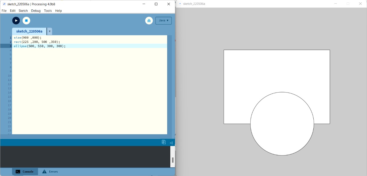
You can Draw many shapes by write it in order like layers the processing software read the code start from top to bottom so it will draw the rectangle first then over write it with the circle.
size(900 ,800);
rect(225 ,200, 500 ,350);
ellipse(500, 550, 300, 300);
●Color
Black & White
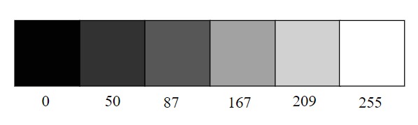
In the digital world, black & white or grayscale. (0) means black, (255) means white. In between, every other number 50, 75 or 209, and so is a shade of gray ranging from black to white.
RGB Color
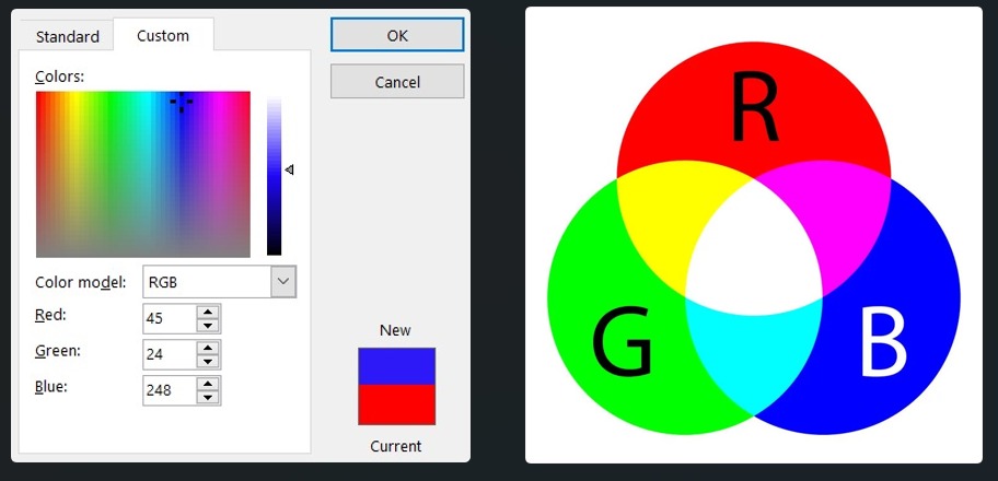
Digital colors are also constructed by mixing three primary colors, As with grayscale, the individual color elements are expressed as ranges from 0 (none of that color) to 255 (as much as possible), and they are listed in the order R, G, and B.
●Stroke / Fill / background
By adding the stroke() and fill() functions before something is drawn, we can set the color of any given shape. There is also the function background(), which sets a background color for the window.
-
A stroke is a line of color that precisely follows a path, and its the outline of the shape
-
A fill is a color enclosed by a path. and its the inner fill of the shape
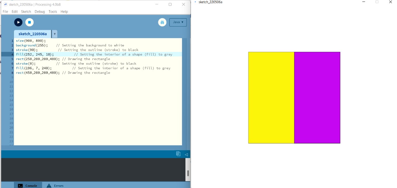
Size(900, 800);
background(255);    // Setting the background to white
stroke(90);          // Setting the outline (stroke) to black
fill(252, 245, 10);          // Setting the interior of a shape (fill) to grey
rect(250,200,200,400); // Drawing the rectangle
stroke(0);          // Setting the outline (stroke) to black
fill(196, 7, 240);          // Setting the interior of a shape (fill) to grey
rect(450,200,200,400); // Drawing the rectangle
●IF , else Statment
If Allows the program to make a decision about which code to execute.
else Extends the if structure allowing the program to choose between two or more blocks of code.
If I click the yellow rectangular showup If not the Purple rectangular showup
void setup() { size(900, 800); }

void draw() {
background(255);

if (mousePressed)

{
stroke(90);          // Setting the outline (stroke) to black
fill(252, 245, 10);          // Setting the interior of a shape (fill) to grey
rect(250,200,200,400); // Drawing the rectangle
}

else

{ stroke(0);          // Setting the outline (stroke) to black
fill(196, 7, 240);          // Setting the interior of a shape (fill) to grey
rect(450,200,200,400); // Drawing the rectangle

}

}
▶ Arduino + processing

The Processing IDE works for a computer like the Arduino IDE works for a micro-controller. The Processing IDE can communicate with the Arduino IDE through serial communication, and thats what we need to apply for this weeks assignment.
First application:
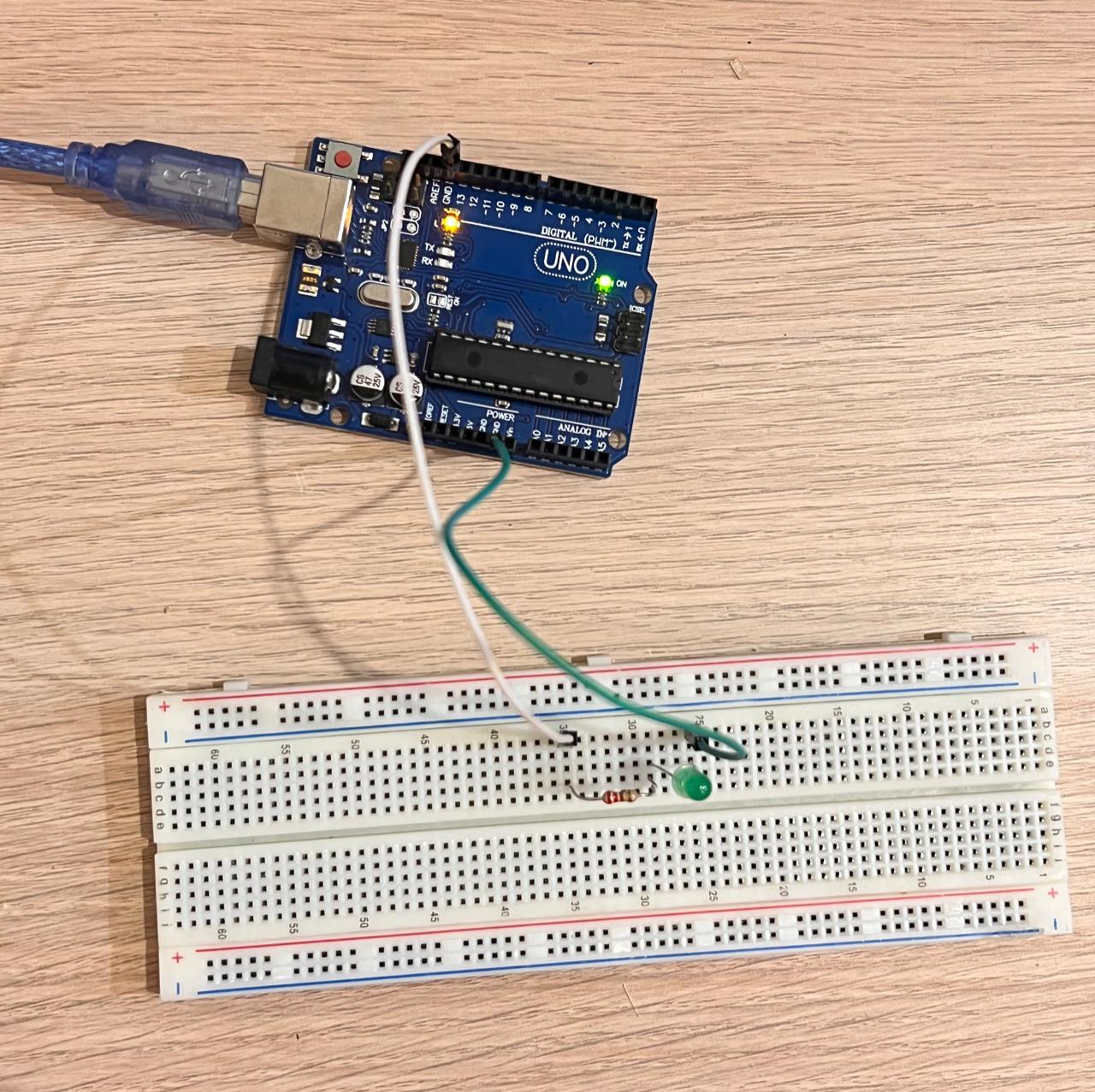
Start connection of the LED
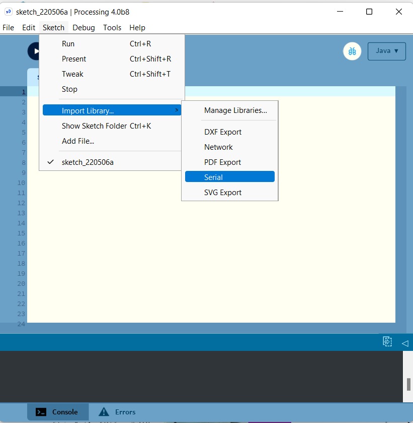
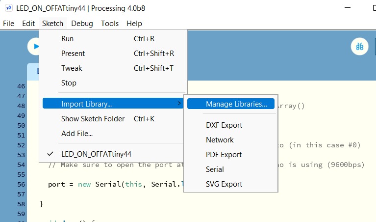
Connect Arduino to Processing by Import the library for a serial communication
Sketch > Import library > Serial

write a program in processing that interact with Arduino by using If Statment
set the com port that Arduino is connected in my case its COM3 ” change it according to your setting
Left Click > Purple > LED OFF
Right Click > Yellow > LED ON
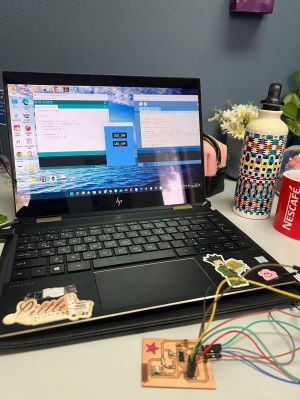
▶ ATatiny44 + processing
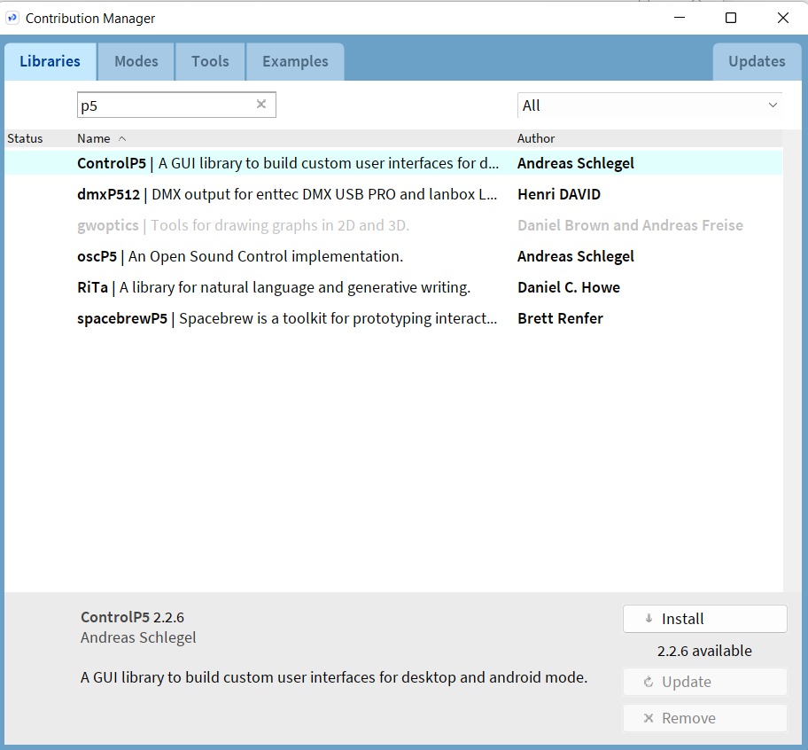
Create a GUI using By Using P5 Library. The P5 library allows you to control and interact with Arduino,
Sketch- > Import Library -> Add Library and than install ControlP5 library
add the P5 library then click install
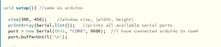
After adding the p5 library now I want to control my LED so I create objects In the (( void setup() )) I set window size like 300x450 and the COM for me is COM6
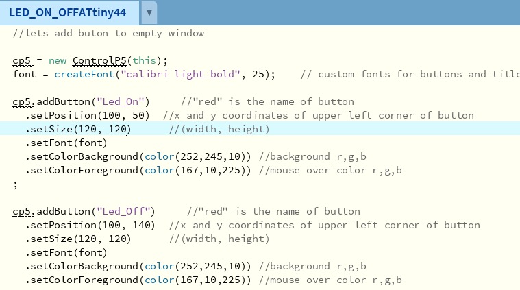
now add 2 Buttons (part of the ControlP5 library) ON and OFF buttons I can control everything in my window so I set the position of the Buttons and the color of the background and foreground and the size
Processing code
import controlP5.*; //ControlP5 GUI library
import processing.serial.*;  //Serial library

Serial port;  //serial object
String myText="";  //string text
ControlP5 cp5; //ControlP5 object
PFont font;    //font object

void setup(){ //same as arduino

  size(300, 450);    //window size, (width, height)
  printArray(Serial.list());   //prints all available serial ports
  port = new Serial(this, "COM8", 9600);  //i have connected arduino to com4
  port.bufferUntil('\n');

  //lets add buton to empty window

  cp5 = new ControlP5(this);
  font = createFont("calibri light bold", 25);    // custom fonts for buttons and title

  cp5.addButton("Led_On")     //"red" is the name of button
    .setPosition(100, 50)  //x and y coordinates of upper left corner of button
    .setSize(120, 70)      //(width, height)
    .setFont(font)
    .setColorBackground(color(0, 25, 51)) //background r,g,b
    .setColorForeground(color(0, 51, 103)) //mouse over color r,g,b
  ;

  cp5.addButton("Led_Off")     //"red" is the name of button
    .setPosition(100, 140)  //x and y coordinates of upper left corner of button
    .setSize(120, 70)      //(width, height)
    .setFont(font)
    .setColorBackground(color(0, 25, 51)) //background r,g,b
    .setColorForeground(color(0, 51, 103)) //mouse over color r,g,b
  ;
}

void serialEvent (Serial port){
  myText = port.readStringUntil('\n');
}

void draw(){  //same as loop in arduino

  background(102, 178 , 255); // background color of window (r, g, b)

  //lets give title to our window
  fill(0, 0, 0);               //text color (r, g, b)
  textFont(font);
  text("LED CONTROL", 70, 30);  // ("text", x coordinate, y coordinat)
}

//functions to send over serial when buttons is pressed

void Led_On(){
  port.write('n');
}

void Led_Off(){
  port.write('f');
}
Arduino Code
Now in the Arduino IDE set the SoftwareSerial communication because I use ATtiny44, I connect the VCC and GND then TX and RX (PB0 & PB1) to my ATtiny44.
int ledPin = 8 ; >> the LED pin in my board from my schematic
then connect your wires upload the Arduino code and open the processing code then click Play now
Code below
#include <Mouse.h>
#include <SoftwareSerial.h>

SoftwareSerial TinySerial(1, 0); // RX, TX

int ledPin = 8;

void setup()
{
  TinySerial.begin(9600);
  pinMode(8, OUTPUT);
}
void loop()
{
  if(TinySerial.available() > 0) {
    char ledState = TinySerial.read();
    if(ledState == 'n'){
      digitalWrite(8, 1);
    }
    if(ledState == 'f'){
      digitalWrite(8, 0);
    }

  }

}
when I click (LED-ON) it will send an ‘n’ the LED will turn ON and If I click (LED-OFF) it sends an ‘f’ and the LED to turn off
▶ File
▶ Group assignment
Compare as many tool options as possible.