11. Input devices
▶ Individual assignment
- Measure something: add a sensor to a microcontroller board that you have designed and read it.

An input is data that a computer receives. An output is data that a computer sends.
In this week, I decided to work smarter so I start designing new circuits to work with input and output devices.
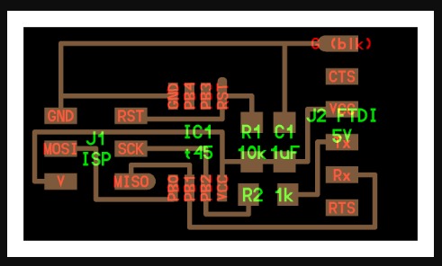
First I open the hello world using ATtiny45.
Component:
- ATtiny45.
- ISP header.
- capacitor.
- Resistor.
- FTDI header.
- 3*1 pin header.
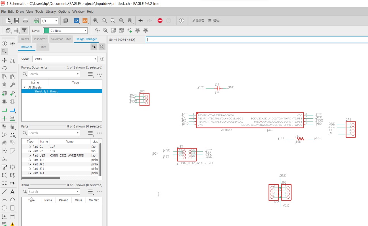
● The Schematic
I designed the PCB by using Eagle SOFTWARE here I explain how to download it and use it WEEK7 assignment.
Open the Eagle software then click
File > New > Project
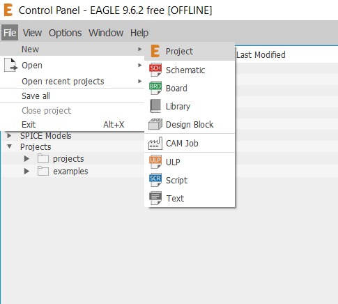
then the blank page will open go to the Add Part
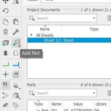
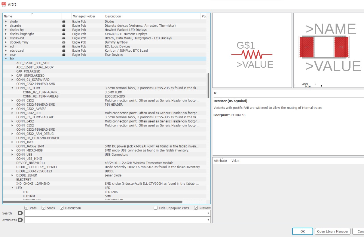
The library will open go to Fab library (We download it before) the click the components you need then click OK
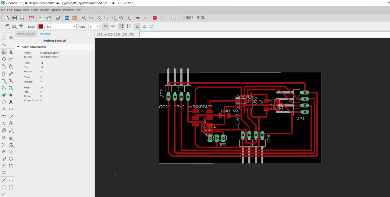
Created a new schematic > Add all the components > Connect the wires > Design rules
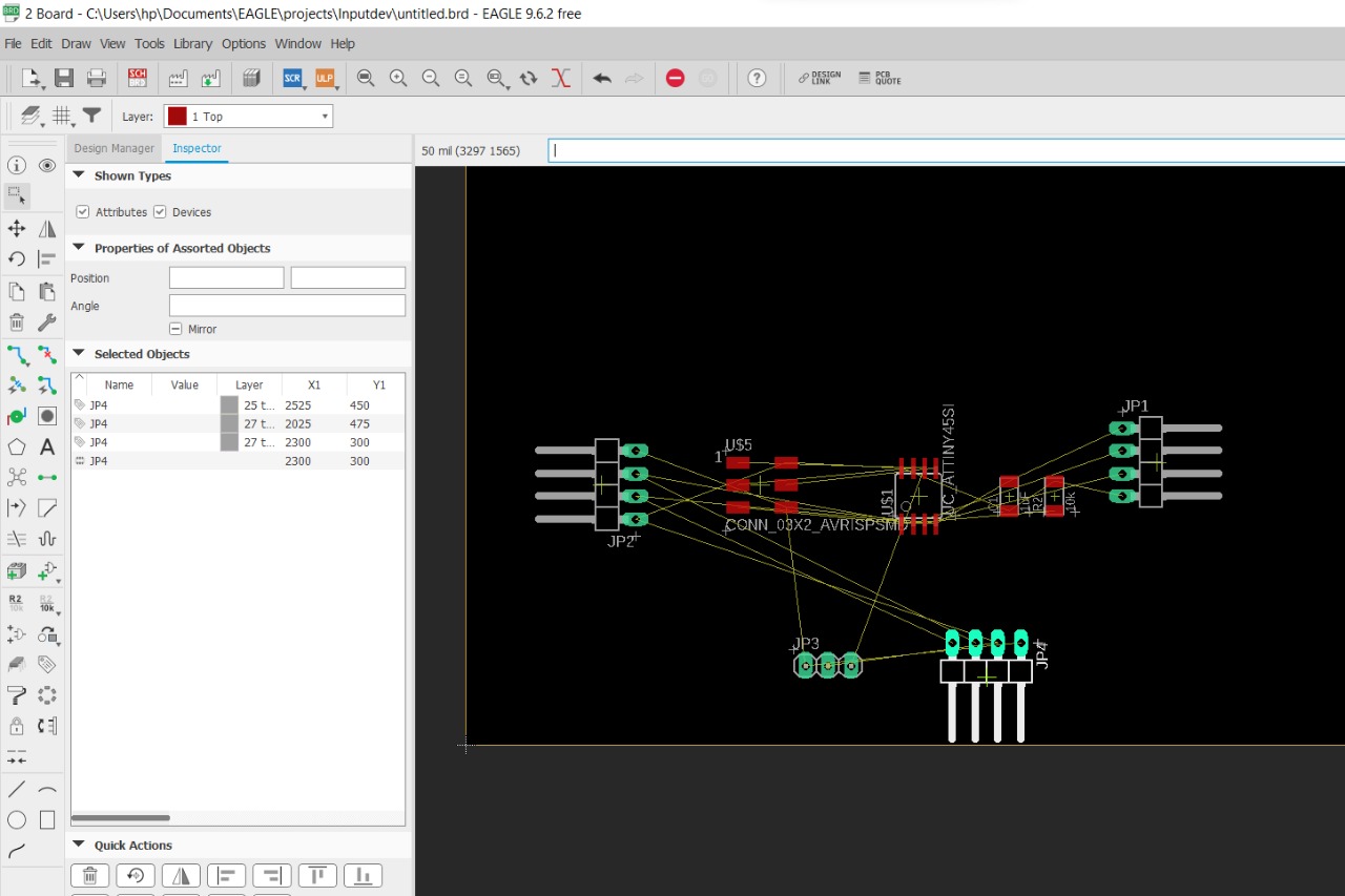
Generate / Switch to board > Connect the wires
(( Before connect the wires be sure to do ))
Grid > Size 0.001 mil. to make you move freely
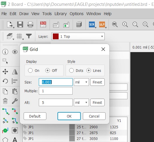
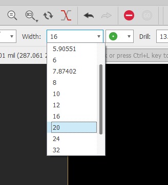
Width or wires > 20
Now Click Rout Airwire and connect the wires manually
Now hide all layers and export the Top layer (Trace) and the Dimension layer (Outline) separately
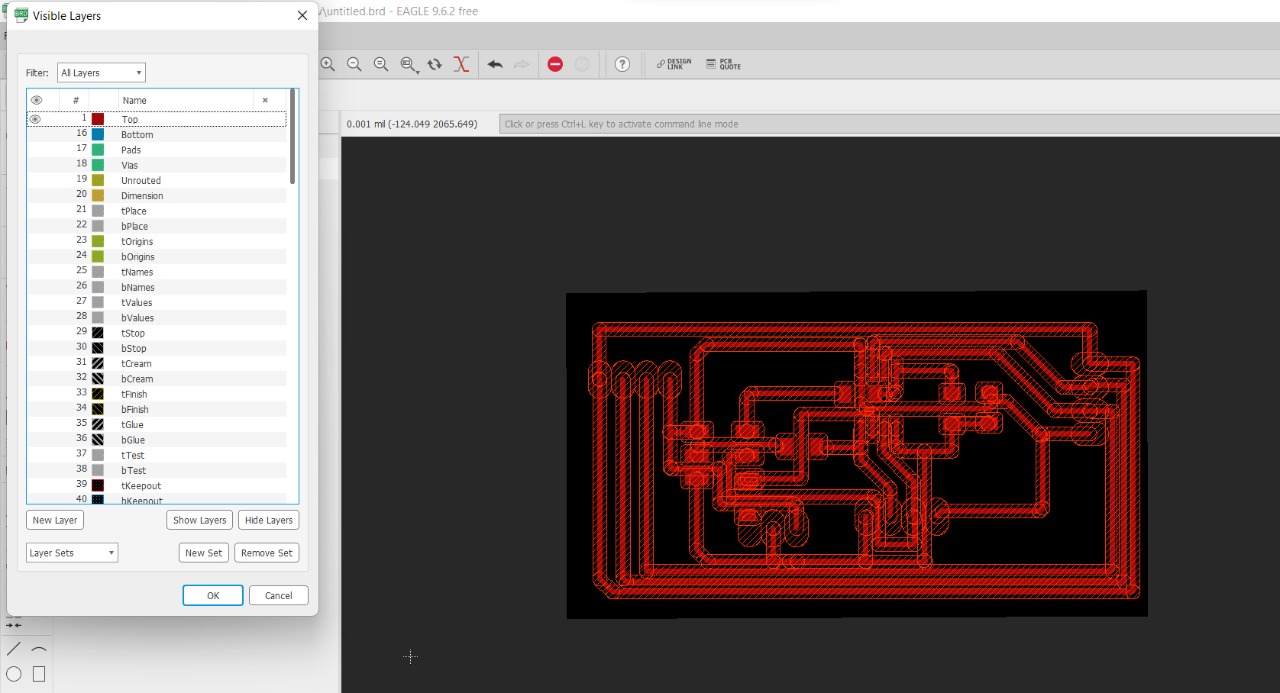
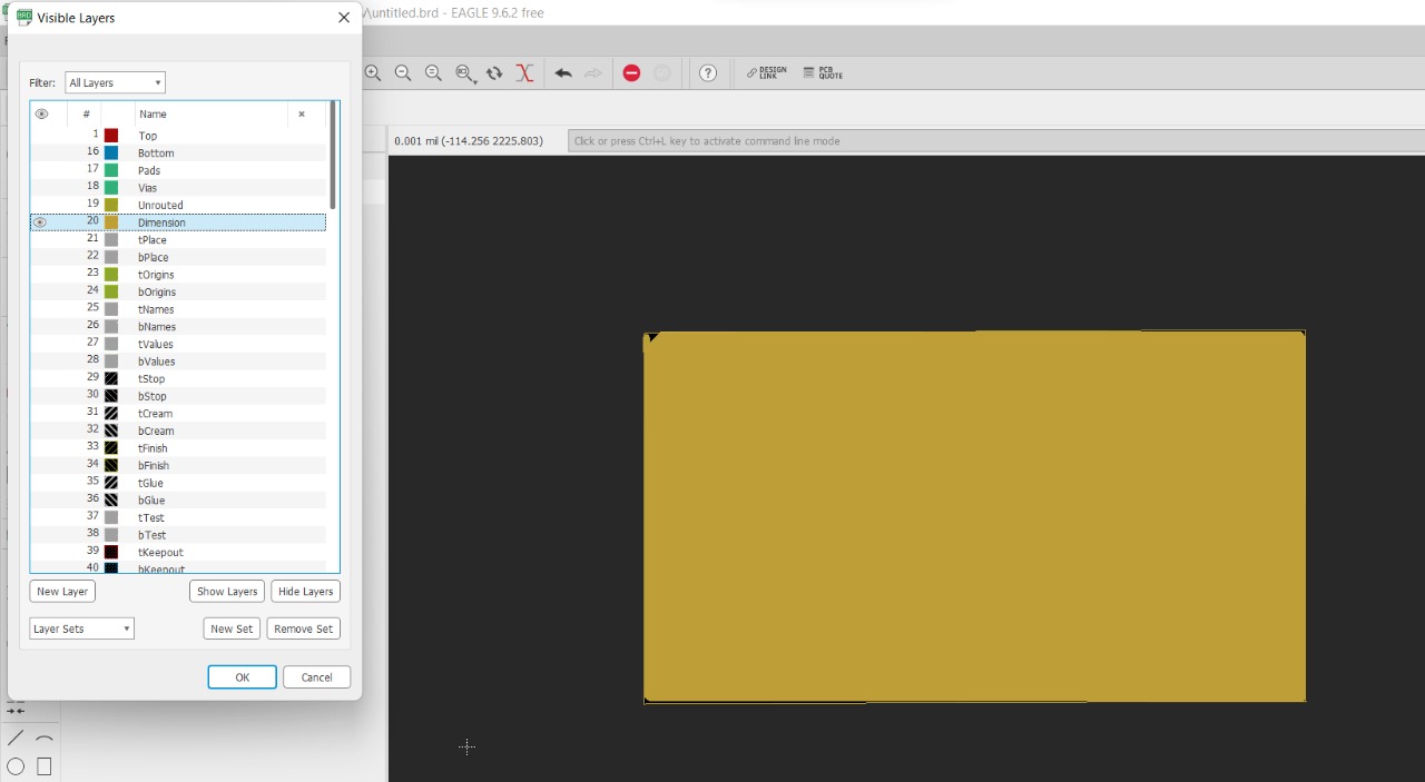
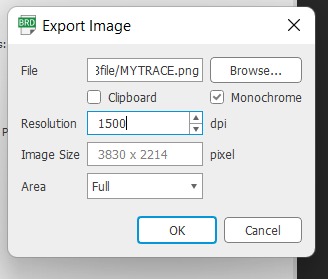
File > Export > Image > Resolution 1500 dpi and check Monochrome
● Trace and Outline
Now Send it to MODS.
- Trace & Outline
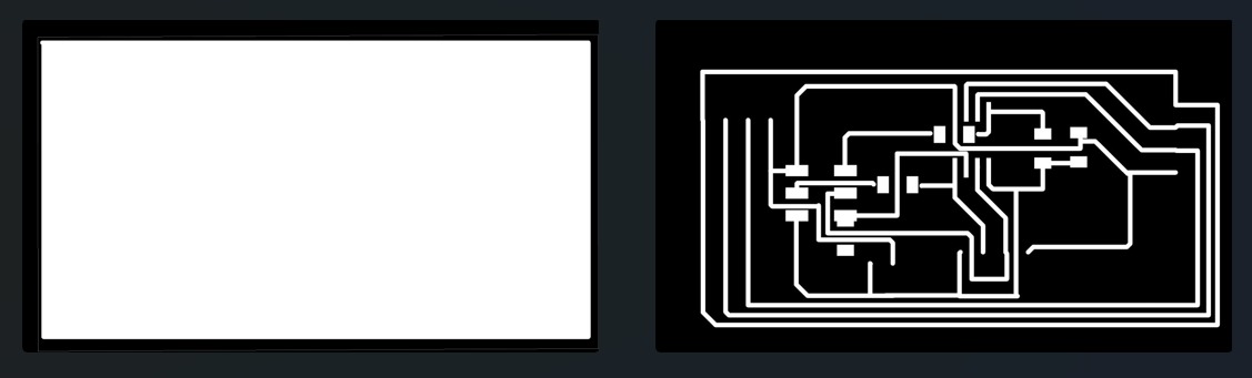
- Final Cutting
● Soldering
Before I start Soldering Here I notice some short circuit so I try to fix it but the trace cut so I try to do jumper by soldering
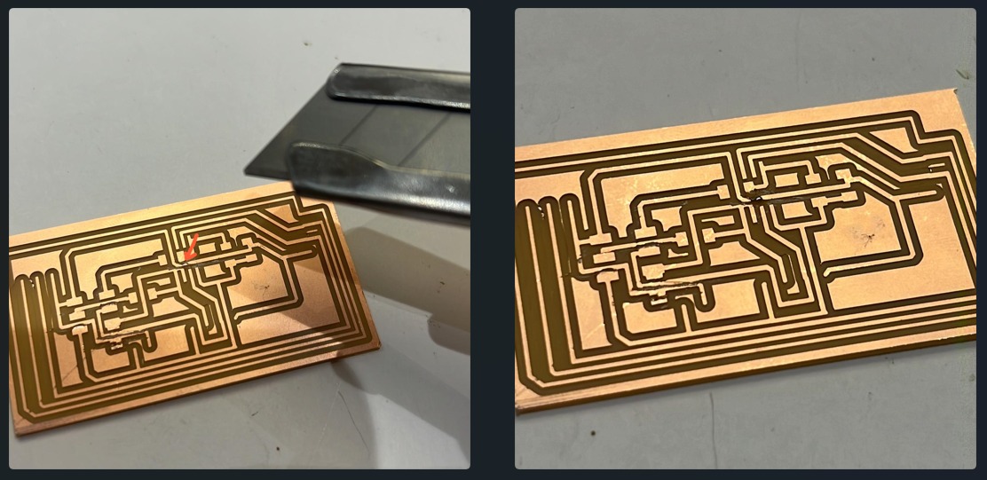
And I Start Solder all components
● Programming
To start programming ATtiny45 With Arduino as ISP
First open File > Preferences.
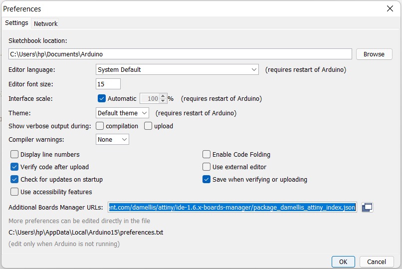
at the bottom you can see “Additional Boards Manager URLs” you want to copy and paste https://raw.githubusercontent.com/damellis/attiny/ide-1.6.x-boards-manager/package_damellis_attiny_index.json then click OK.
Tools > Board > Board Manager.
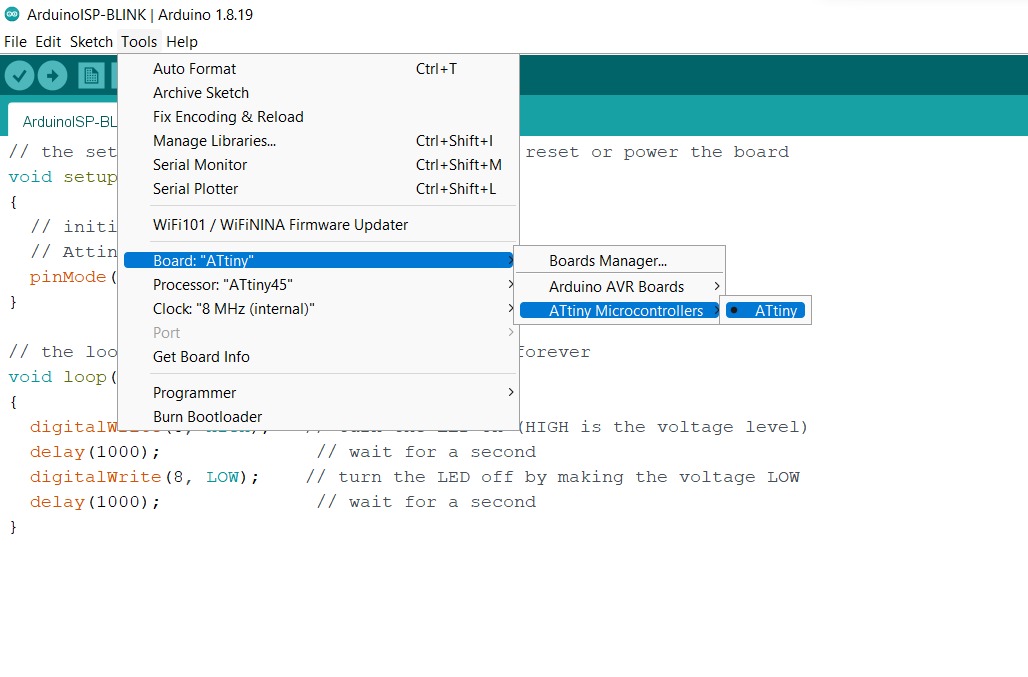
and you should see ATtiny from Tools > Board
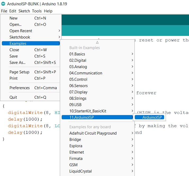
File > Examples > ArduinoISP. Open the sketch and upload it to your Arduino.
after uploead the ArduinoISP New page will show up; go to
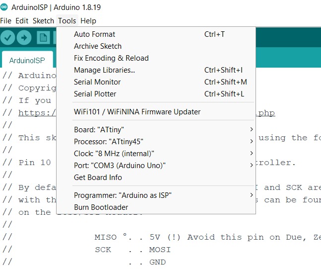
from Tools > Board > ATtiny.
Tools > Processor > ATtiny 45.
Tools > Clock > 8 MHz (Internal)
Programmer > Arduino as ISP
connector to the Arduino UNO pins as following:
-
Arduino Pin 13 —> SCK
-
Arduino Pin 12 —> MISO
-
Arduino Pin 11 —> MOSI
-
Arduino Pin 10 —> RESET
-
Arduino Ground —> GND
-
Arduino 5V —> VCC
After you connect Arduino ISP pins go to
Tools > Burn Bootloader
Push Button
I Start with digital Read Serial Monitor with Button BUT First we need to know how push button work
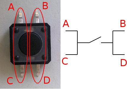
A Push Button is a type of switch work on a simple mechanism called “Push-to-make”. Initially, Two legs on both the sides are internally connected as shown in the figure above.
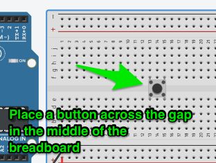
The structure has four legs, two on one side and other two on another side. So, we can operate two lines of the circuit by single Push Button and here Explain why we connect the button cross in bread board.
Code Explanation:
Defining the Pins LED and the switch
#define LedPin 1
#define SwitchPin 2
Defining the LED as the output device and the Push Button as Output device.
 void setup()
pinMode(SwitchPin,INPUT);
pinMode(LedPin,OUTPUT);
The Result
When the push button is Unpressed there is no connection between the two legs so the pins is connected to the ground because of this reads as LOW or 0
LDR (Photoresistor)
Light Dependent Resistor Sensor
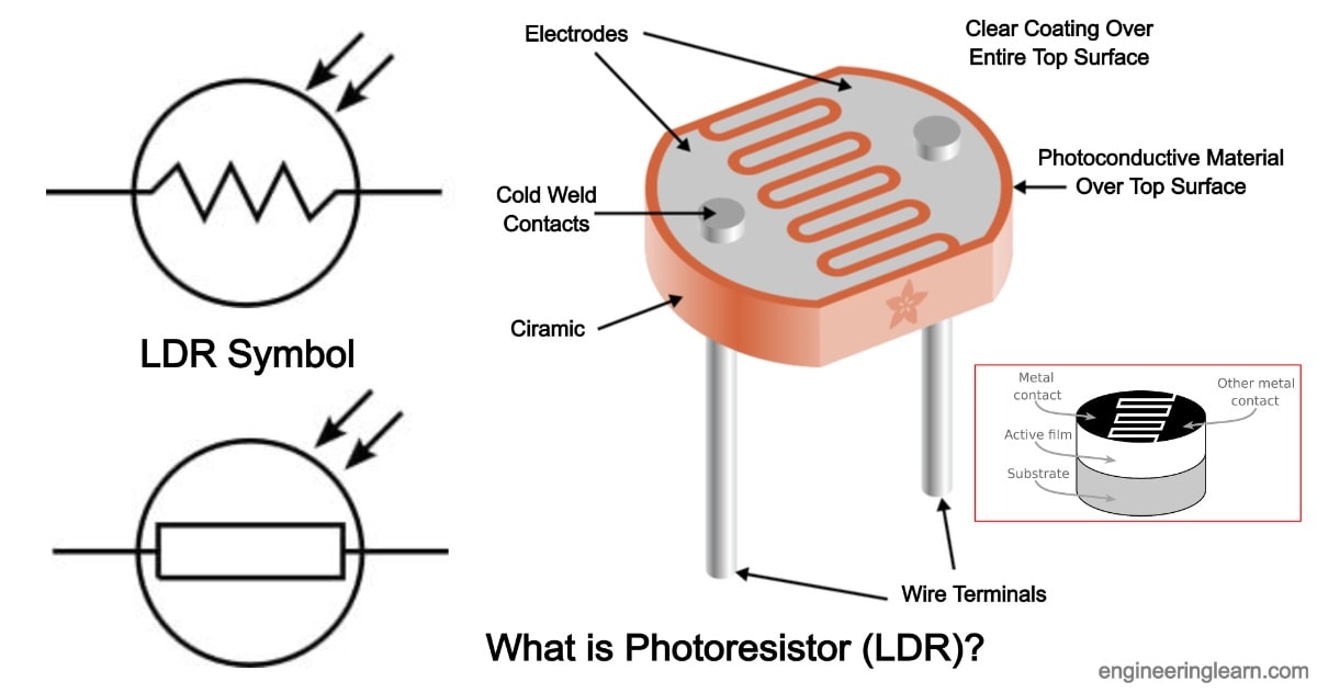
LDR is Light Dependent Resistor, These LDRs or PHOTO RESISTORS works on the principle of “Photo Conductivity”.
Code Explanation:
Defining the Pins LED and LDR As Output and Input
int LDRSensor = A1;
int led =0;
In the VOID SETUP, declare PIN 0 ( output ) with the pinMode command, which will be use to change the logic state to the high value by turn the LED OFF.
// the setup function runs once when you press reset or power the board
void setup() {
  // initialize digital pin LED_BUILTIN as an output.
  pinMode(led, OUTPUT);
   pinMode(LDRSensor, INPUT);
}
I the VOID LOOP we declare the analog value of the input of pin A1. we use an IF condition to compare if the value of my variable is greater than or equal to 70 the process changing the logical value of pin 0 turn 0ff the led. If not, I use the ELSE condition where it ensures the low status of pin number 0.
// the loop function runs over and over again forever
void loop() {
    int LDRval = analogRead(LDRSensor);
    float ldr = LDRval * (100.0 / 1023.0);
    if ( ldr >= 70   )
    {
  digitalWrite(led, HIGH);   // turn the LED on (HIGH is the voltage level)

    }
    else
    {
  digitalWrite(led, LOW);    // turn the LED off by making the voltage LOW
    }

}
upload your code and follow the same steps that we followed in Electronic design assignment WEEK 7.
The Result
The connection by using Breadboard
How Does It Work?
As you see when I cover the LDR Sensor the LED will turn ON and IF I remove my hand and make the LDR observe the light The LED will turn OFF So the logic state is IF the value of my variable is LOW and I mean by low (lower than the natural degree of the light the LDR observe it which is here 70 as the serial mentor show me) the LED will turn ON and IF the LDR will observe more than 70 the LED will turn ON.
In Serial mentor you can see the value is change dependent in the how much the LDR get light.
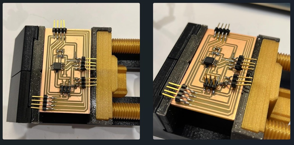
The connection with ATtiny
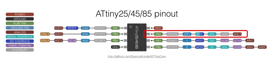
here are the pins on my board
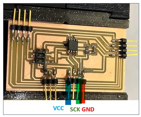
My Connection
here I connect the one leg of LDR with 5V (the power coming from Arduino) then the next leg I connect to the Analong input pin (A1), also we need to use a 100K resistor to make the serial read stable so connect to the same leg (pin A1) and another leg to GND.
Code Explanation
Here I’m designing a different board, to connect the components directly on my board without using jumpers or breadboard
First and by the same steps in the above
Open the eagle software and click File >> New >> project
From the menu on the left chose to add part >> the library will open go to Fab Then add the components you need
the components I need here :
- ATtiny45
- LDR
- LED
- Resistance 10k
- Resistance 220 ohm
- ISP header
The Connection :
here I copied my concept above by creating a new board that will attach to my components without using any intermediate board.
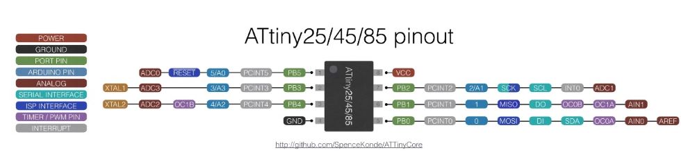
I follow the ATtiny 45 datasheet we can find the information about all the pins, Each microcontroller gas analog, and digital pins, Here we have 3 analog pins and 6 digital pins, The LDR is a sensor that needs analog, and the LED need to connect to a digital pin.
How I connect:
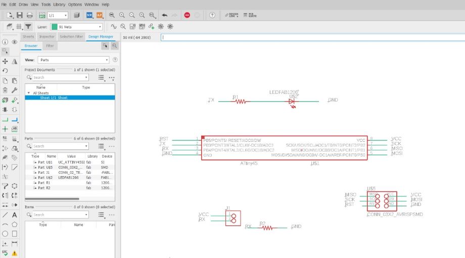
As you see in the Schematic above I start to connect the ISP header with Attiny
-
Arduino Pin 13 —> SCK
-
Arduino Pin 12 —> MISO
-
Arduino Pin 11 —> MOSI
-
Arduino Pin 10 —> RESET
-
Arduino Ground —> GND
-
Arduino 5V —> VCC
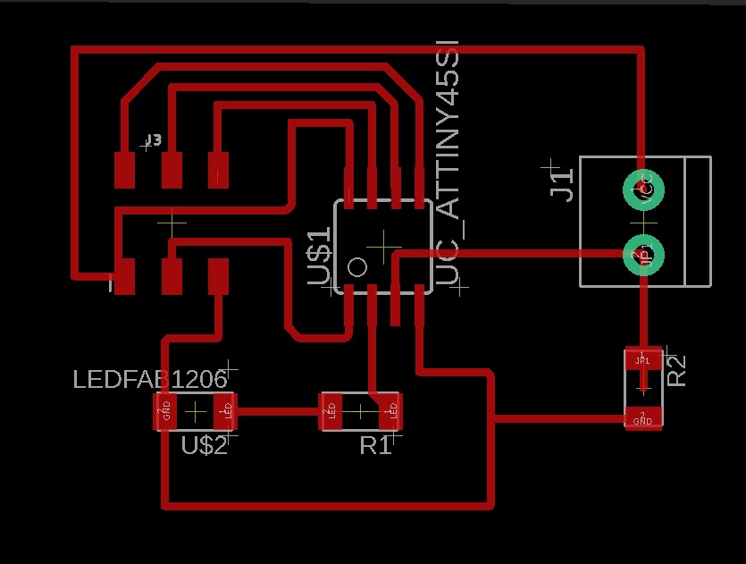
Then I connect the LDR with the VCC and the analong pin (Pin 3) and between them the Resistance connecting with Pin 3 and GND.
and The same with LED I connect one side with VCC and other side with the Resistance then I connect the Resistance with pin2 and GND.
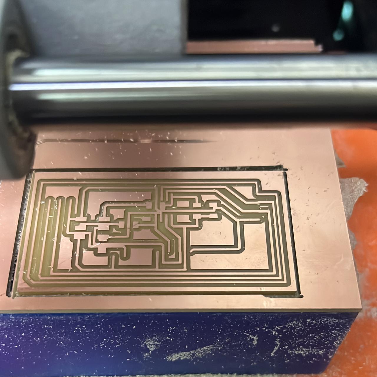
The trace
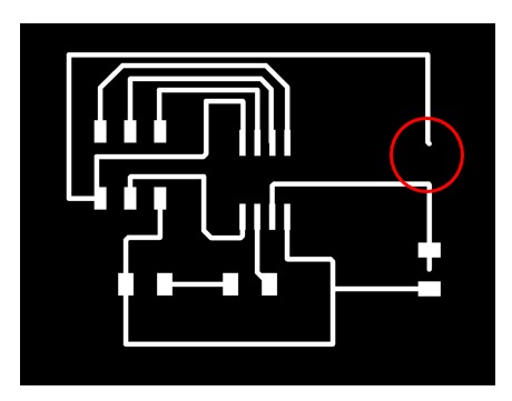
After I export my trace I noticed the LDR place in the trace is empty its looks like something is missing I think about when I start soldering it will be very hard to solder the LDR legs with the board
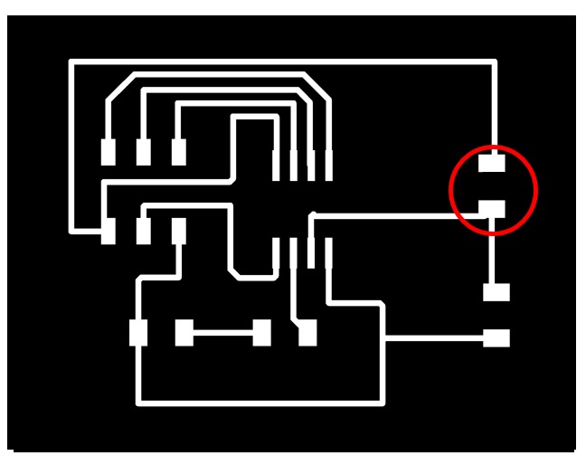
so I replace the 1X2 header with restore footprint to create a good space to solder the LDR.
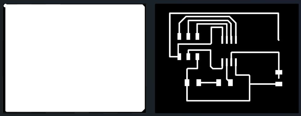
The Trace & outline
References:
- ATTINY-85 Serial Monitor. Step-by-step Arduino IDE Guide
- Push Button LED Circuit
- Arduino Light Sensor Circuit using LDR