4. Computer controlled cutting
Individual assignments:
-
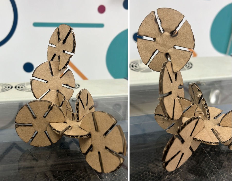
Design, lasercut, and document a parametric press-fit construction kit, which can be assembled in multiple ways. Account for the lasercutter kerf.
-
cut something on the vinylcutter.
lets explain what (press fit) mean
a pressed fit is a form of fastening between two tight-fitting mating parts that produce a joint that is held together by friction after the parts are pushed together without glue or using nails I’m using cardboard because it’s flexible.
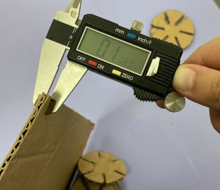
What is Kerf ?
It’s the material removed during the cutting, It is important to know the kerf depends on the nozzle you will use to cut
to measure the kerf you need to cut a square (1 Inch) and then check the size it by using Caliper measure the kerf created { measure the outer dimension of the cut part and the inner dimension of the slot } I did my measurement on cardboard.
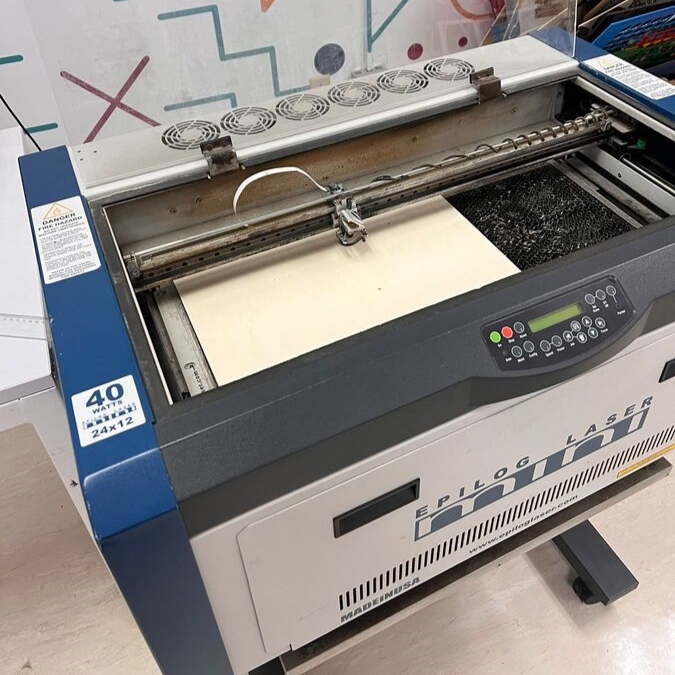
Laser Cutter
# Fusion 360
Since we understand the kerf ana parametric let’s start design out parametric press fit object.
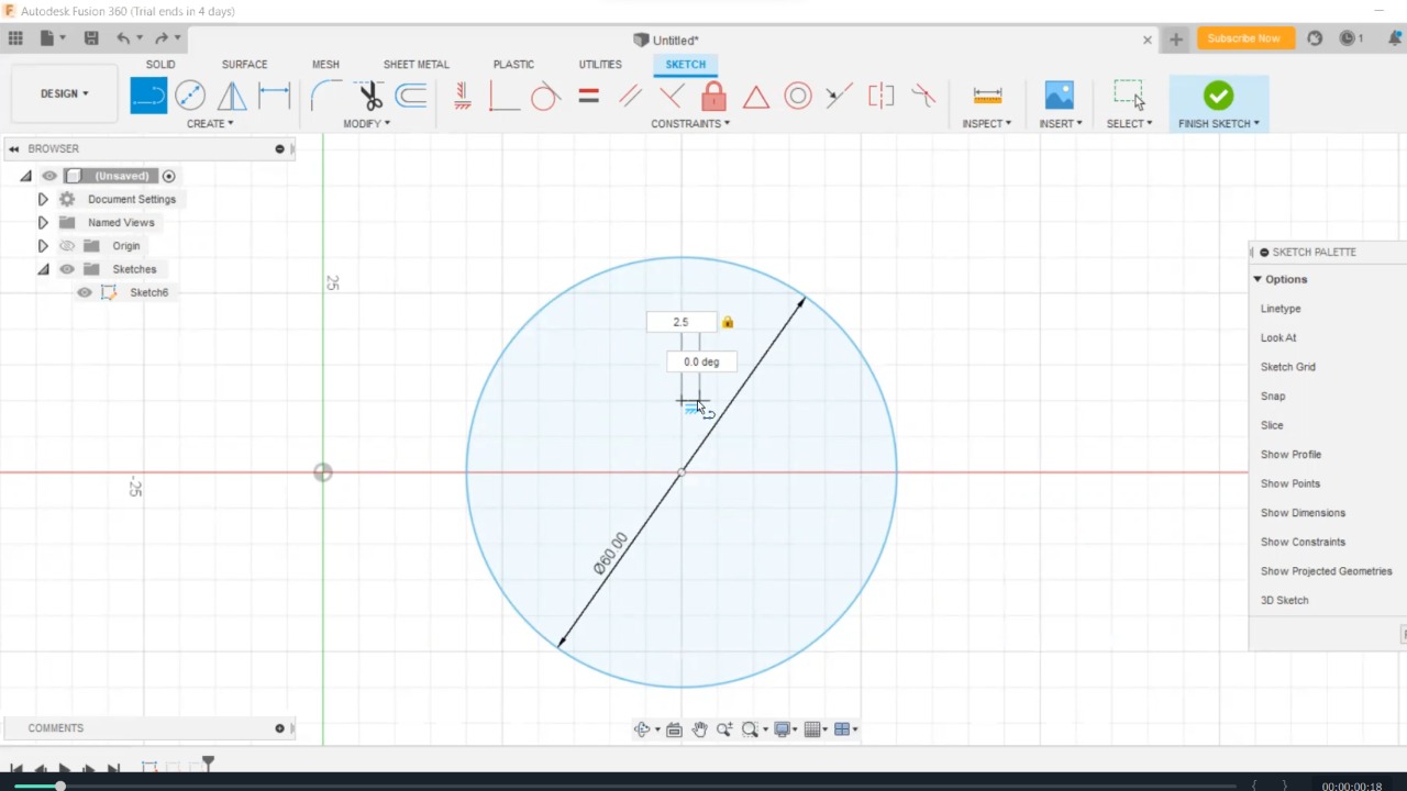
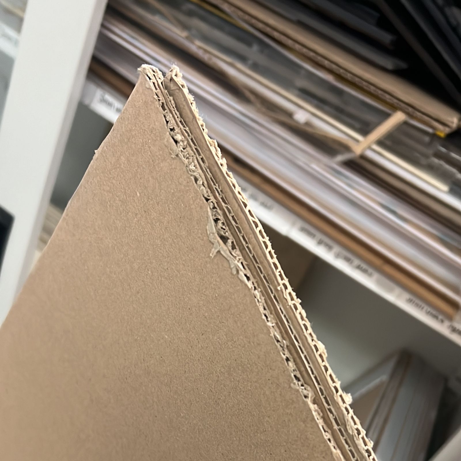
the main component here it’s the material thickness depend on it you can create your press fit design here I’m using Cardboard material (thickness is 2.5 mm)

In Fusion 360, I created a circle with parametric properties.
The main parametric properties related to material thickness and therefore all the connections around the shape you have as well as the width of it.
Since I plan to use cardboard I measured the thickness (0.1 inch = 2.54 mm) based my initial design on this number.
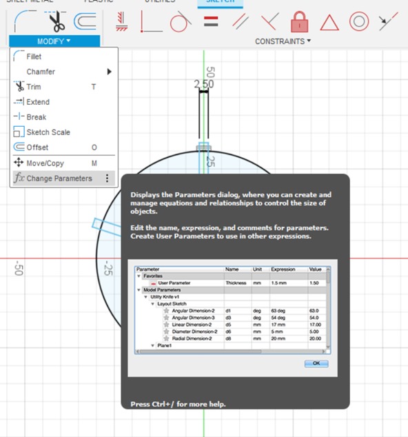
In the modify menu there is an option called Change Parameters where we put the parametric value
Modify > Change Parameters
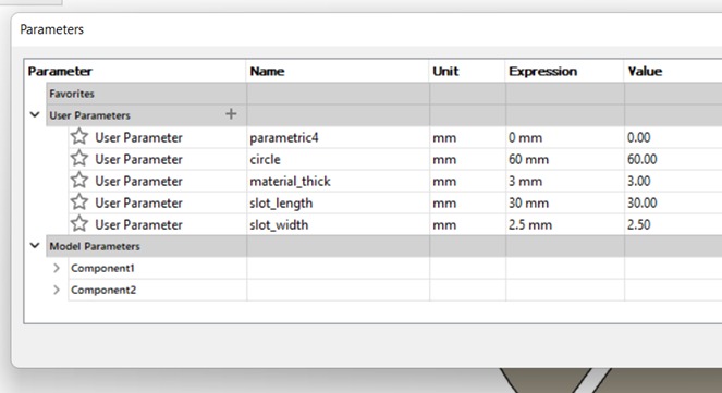
click user parameters the box will appear which you have to put the name of the parameters the units the value and the comments if you want
now you can draw depending on the value of your parameter so start your sketch by drawing the circle when you draw you can write in the dimensioning space the name of the value you need as you see in the picture above I just write C and then the program will understand what value I need the automatically will set you size.
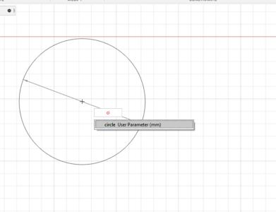
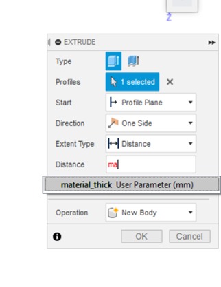
and you can use this feature for all your drawings even the extrude of note in distance option in writing material thickness and the program will automatically get it.
Now let’s explain how I draw my object by using the same parametric technique
Open the Software and first draw a circle
Create > Sketch > Circle
then I draw a small rectangle from
Create > Sketch > rectangle
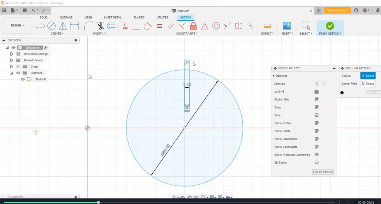
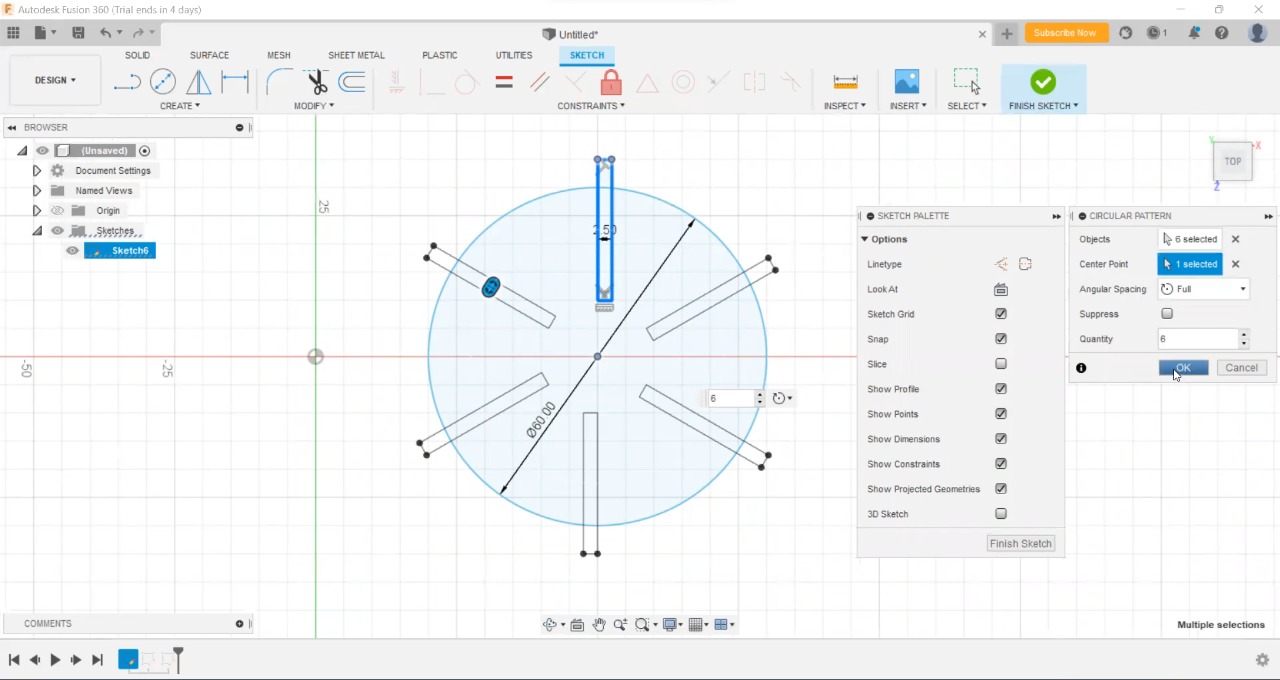
select your Sketch and click Circle pattern
Create > Sketch > Circle pattern > select the object > Center Point > Quantity
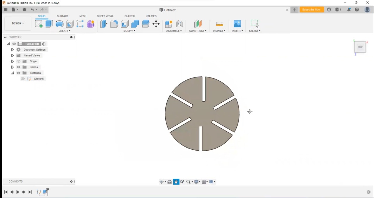
Now cut out the objects by Extrude
Create > Extrude
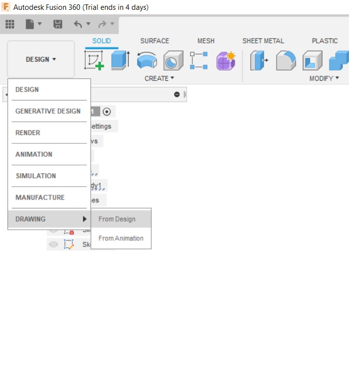
# Export the file for Laser Cutter
Export PDF (or any format the machine can read) for Laser Cutter
Drawing > From Design
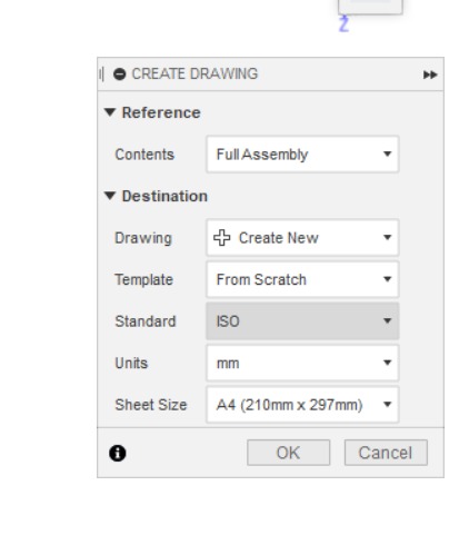
Set the sheet size and the Unit you use to make sure the size fit exactly
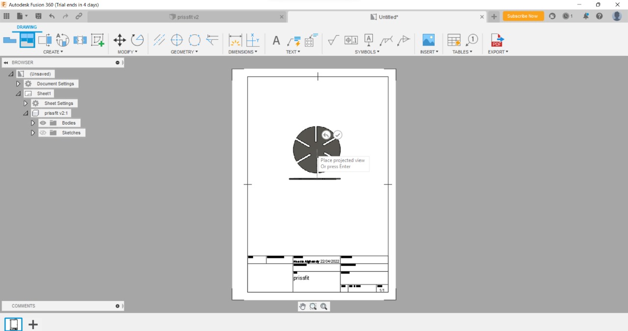
prompted the base view of your drawing
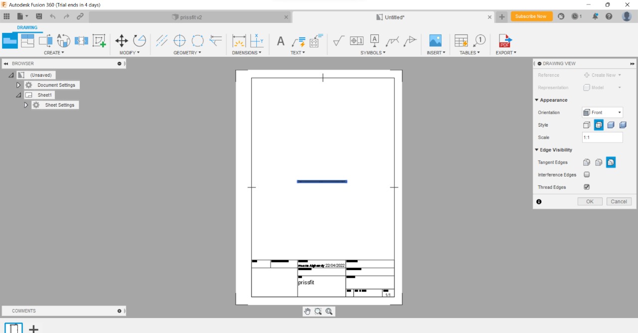
simply click anywhere and the drawing will flip automatically
manually select the table and all the drawings you do not need and delete it
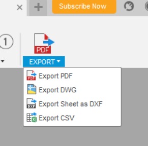
Now select > Export to PDF (up left in the corner)
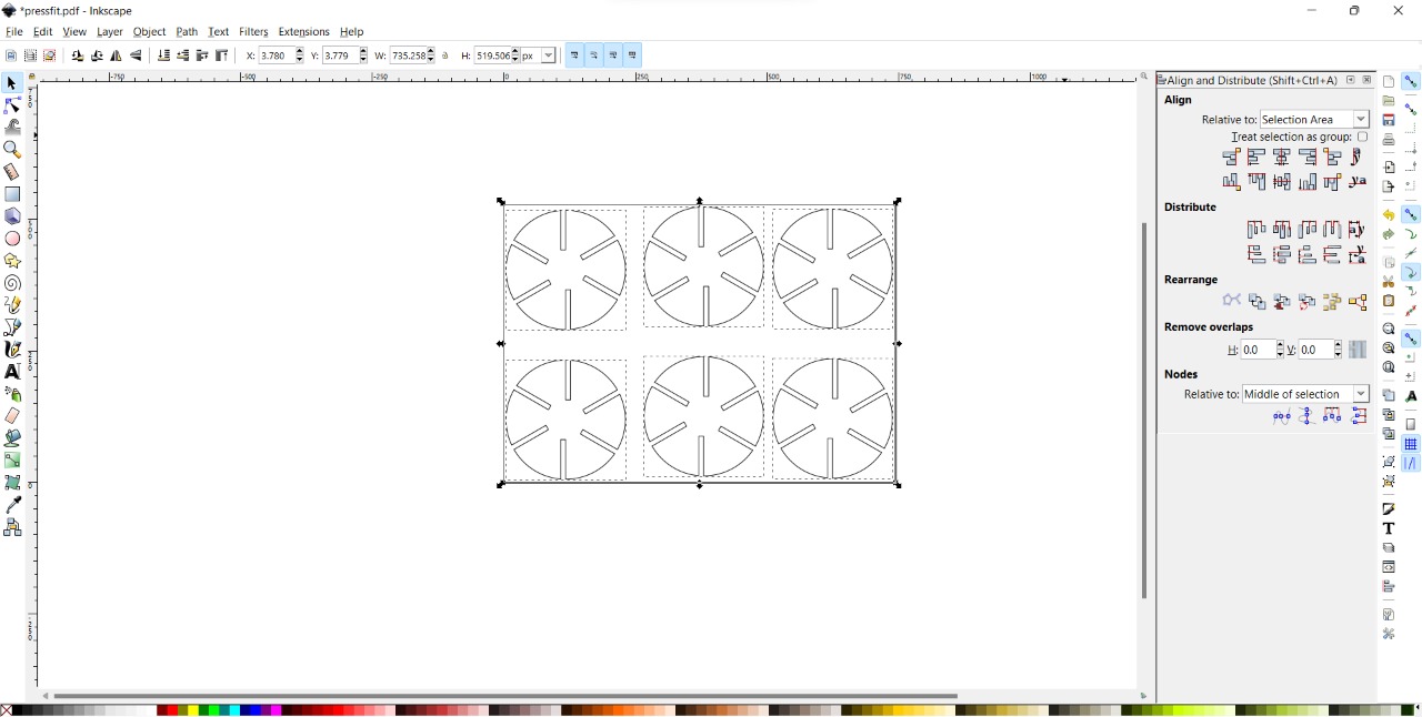
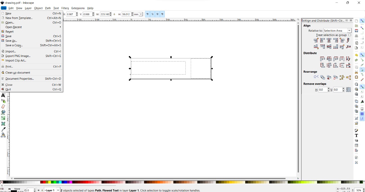
Then open the laser cut Software (Inkscape)

to cut your design arrange it and create copies
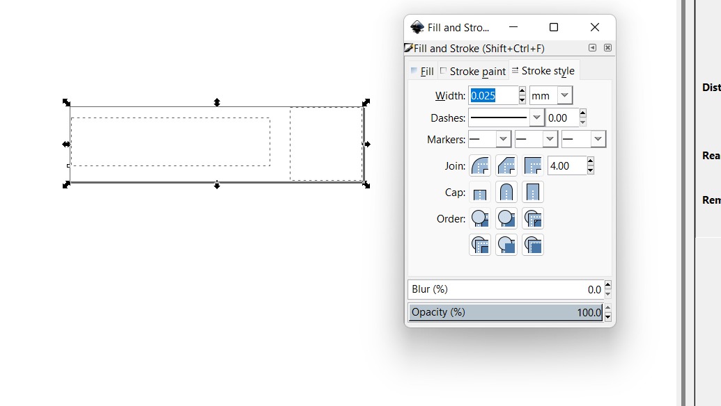
object > Fill and Stroke > Stroke style 0.025mm
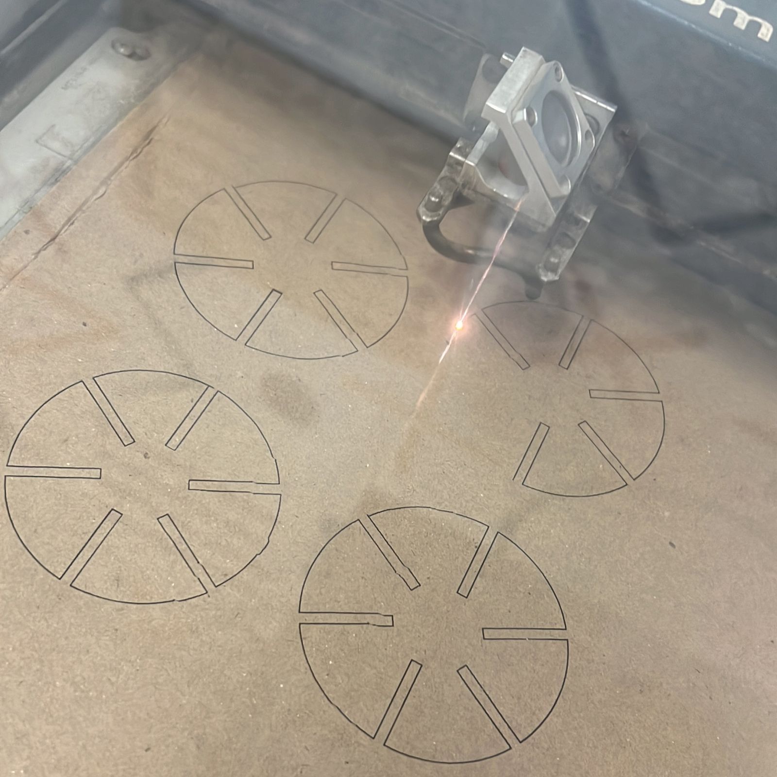
- then, check the machine and the ventilation and everything here seems ok
- Now I put the sheet I used in the machine Laser cut can cut different types of materials (Wood ,Acrylic, copper ,leather and cardboard)
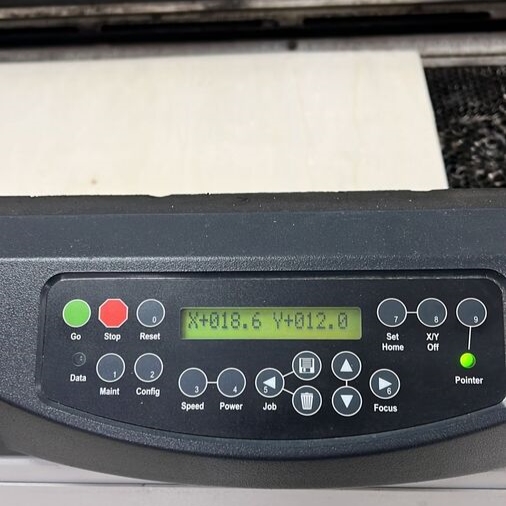
- Set the access X, Y, and Z
- the focus
Inserting the sheet with the same material and thickness as we put in the computer setting.
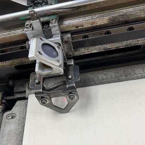
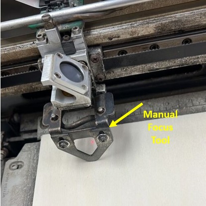
then put the focus tool on top of the lens and click Focus, it will adjust the focus automatic but here it’s broken so we use the arrow in the control panel
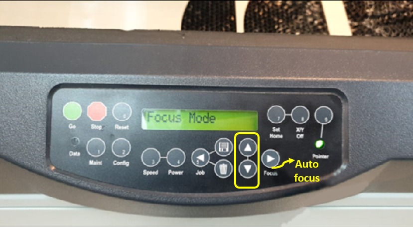
we move the sheet until we see the manual focus tool attached with the material sheet
# Materials settings
I installing the material in the machine the laser machine (30*60 cm) here i’m using 3mm cardboard
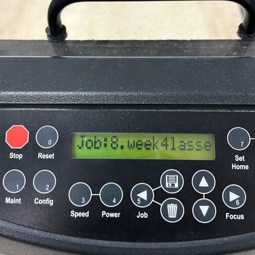
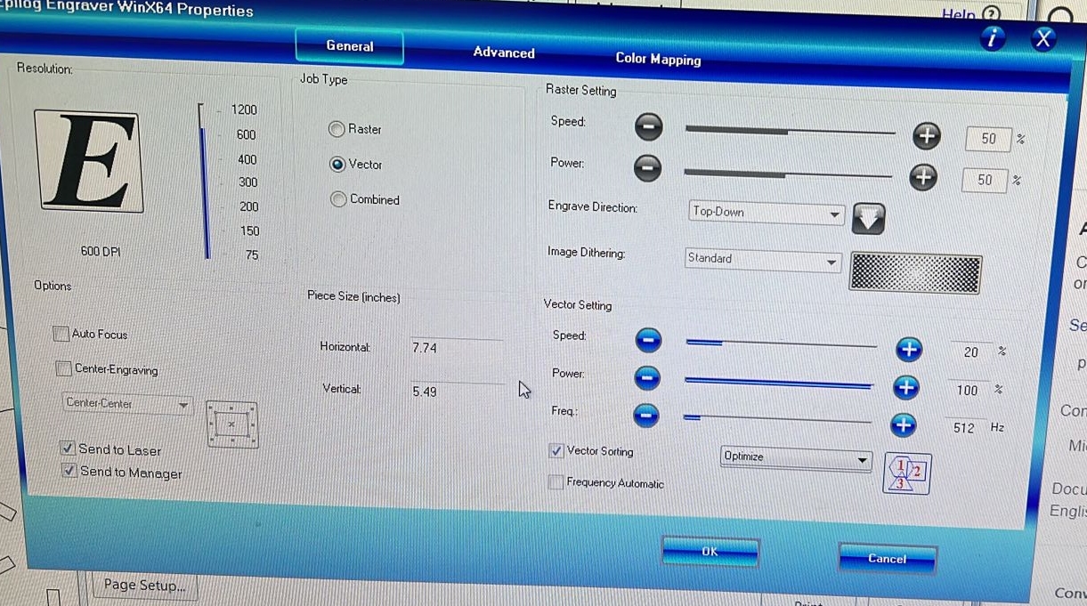
- Print Setup
I search for Power , Speed and Frequency Settings for cardboard material
Power: 50 %
Speed: 50 %
Frequency: 512 Hz
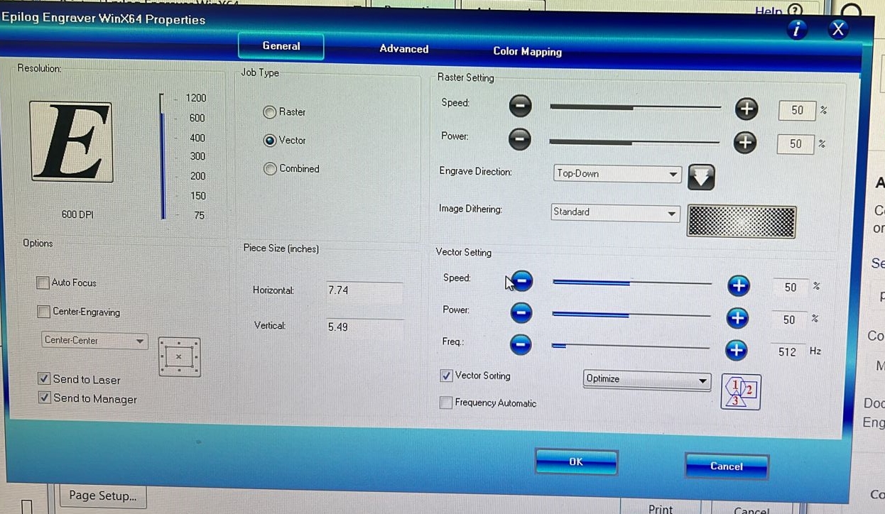
It’s not cut very well so I Change it to
Power: 20 %
Speed: 100 %
Frequency: 512 Hz
- Final result
#Vinyl Cutter
● Inkscape
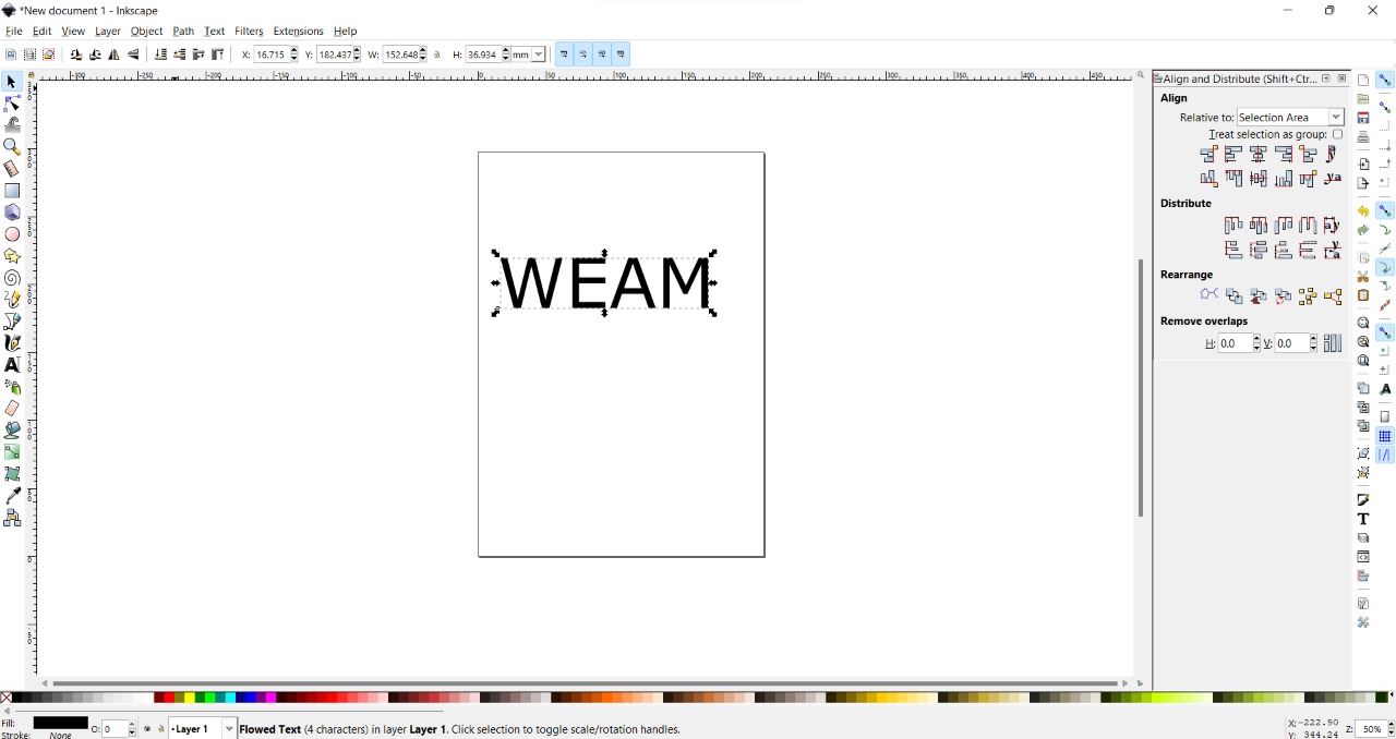
Start with Inkscape
From the tool list (In the left) I choose Text to write my name
modify the text from top > Type font, Size and adjuster
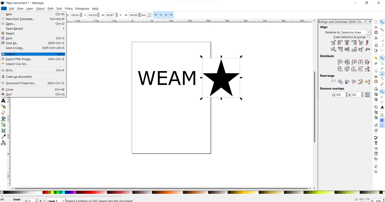
Import an Image to add it in my design
File > Import
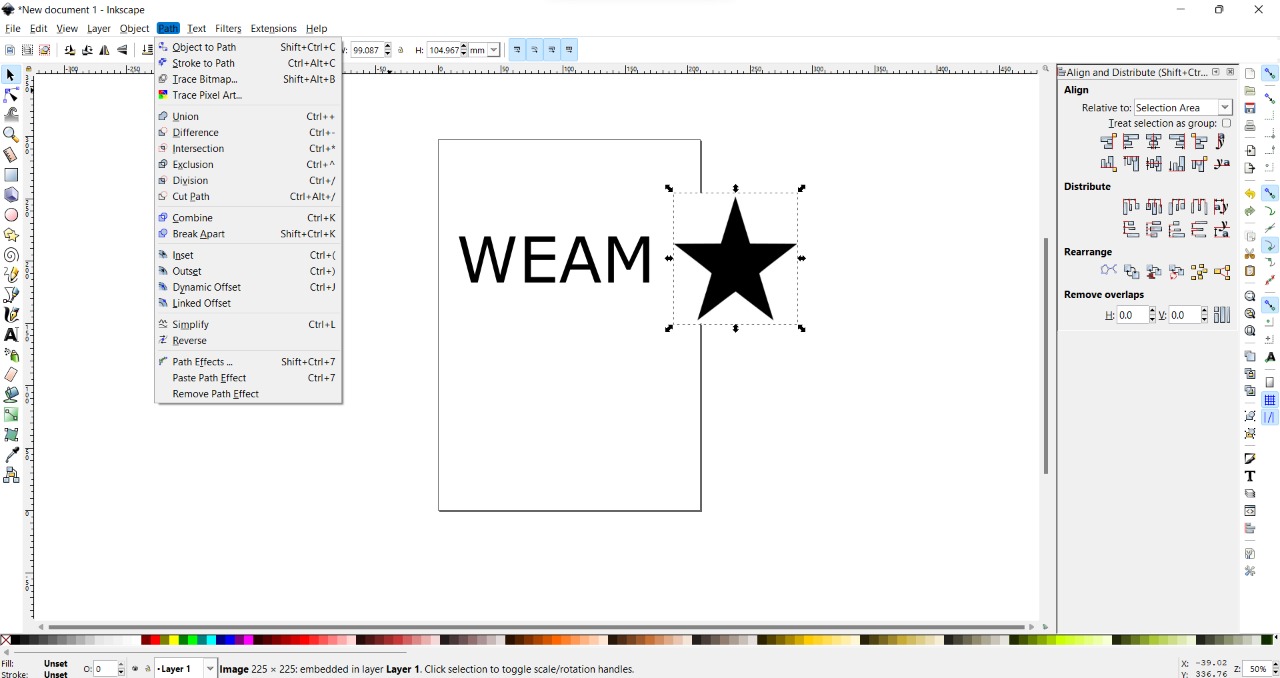
Convert it into vector
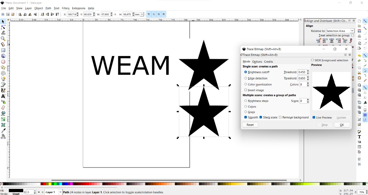
Path > trace bitmap
window will popup click ok and delete the original Image
Live preview > ok
select all and resized the sheet
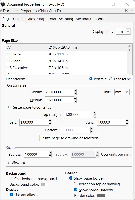
File > documents properties
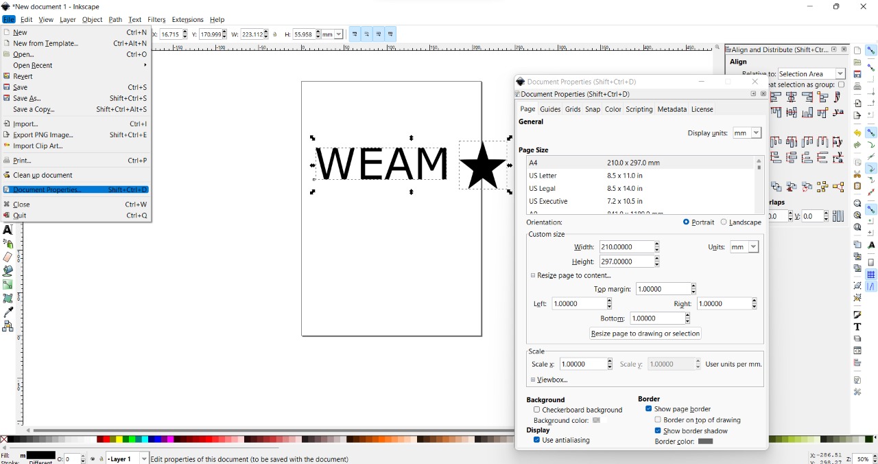
Unites MM and make all margins 1.000 mm and click resized
Fill and Stroke
Fill > X
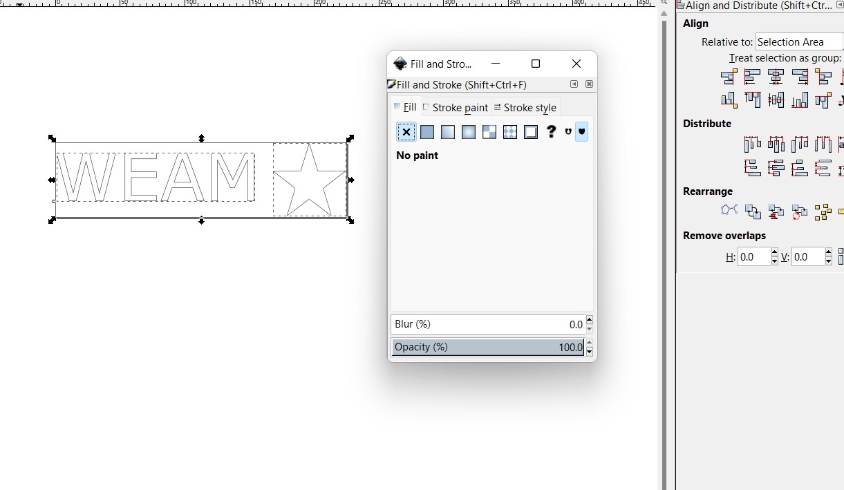
Stroke > Stroke Style 0.025 mm
Save it as PDF
File > Safe as

● Roland GS-24
Here I’m using Roland GS-24 Vinyl Cutter
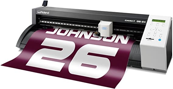
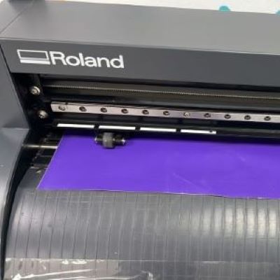
I prepared the material on the machine
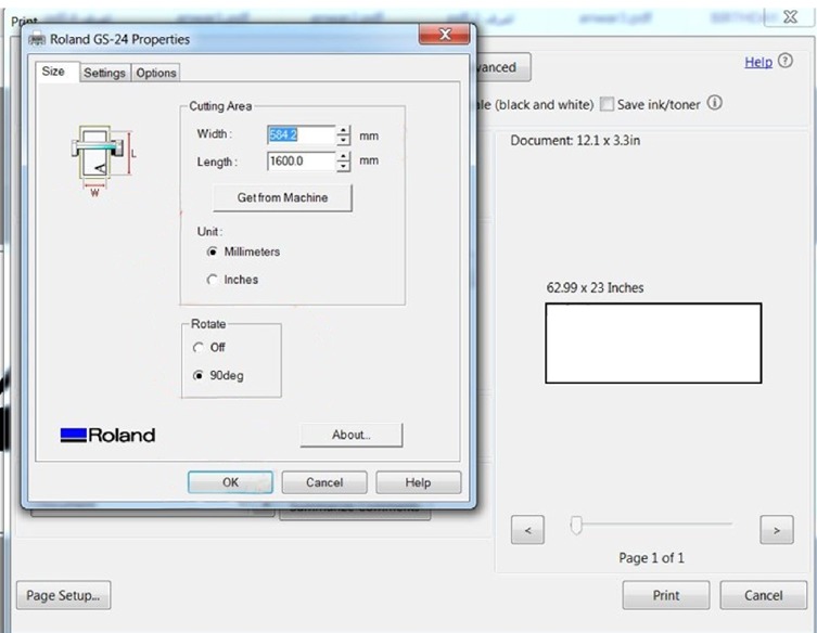
open your design (PDF file) and from the printer menu choose Roland GS-24 then the Roland properties will show up in the cutting area type your design size from Inkscape then click OK and then Print and the machine will start cutting
after the machine cuts, you need to Weed the cutting letters by Applying transfer tape
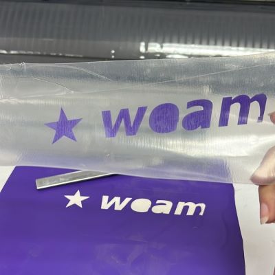
Apply your Design. Peel the transfer tape away from the release liner and It be should come with your transfer tape.
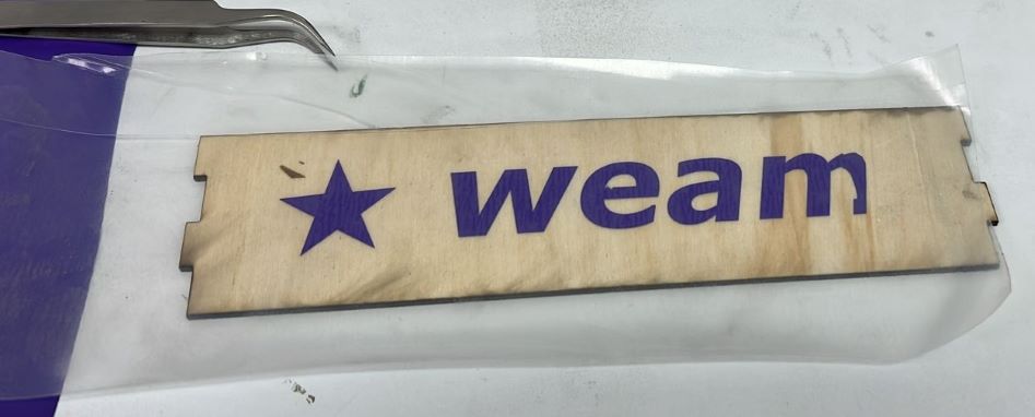
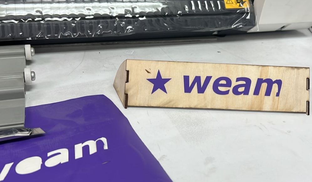
Final result
I have problem with letter M so I cut it manually