14. Networking and communications
⬤ Individual assignment:
∘ design, build, and connect wired or wireless node(s) with network or bus addresses.
Serial Communication
Serial communication protocols have been here ever since the invention of the Morse Code in 1838. Today, modern serial communication protocols use the same principles. Signals are generated and transmitted on a single wire by repeatedly shorting two conductors together. This short acts like a switch; it turns on (high) and off (low), providing binary signals. How this signal is transmitted and received will depend on the type of serial communication protocol used.
Thus the invention of serial protocols such as UART, I2C, and SPI. Although these serial protocols are several decades old, they are still preferred for microcontrollers and bare-metal programming.
UART (Universal Asynchronous Receiver-Transmitter)
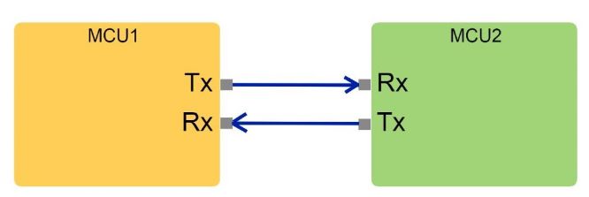
The UART protocol is one of the oldest yet most reliable serial communication protocols we still use today. This protocol uses two wires known as Tx (transmit) and Rx (Receive) for both components to communicate.
SPI (Serial Peripheral Interface)
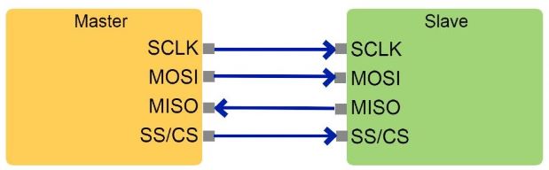
SPI is another popular serial protocol used for faster data rates of about 20Mbps. It uses a total of four wires, namely SCK (Serial Clock Line), MISO (Master Out Slave In), MOSI (Master In Slave Out), and SS/CS (Chip Select). Unlike UART, SPI uses a master-to-slave format to control multiple slave devices with only one master.
I2C (Inter-Integrated Circuit)
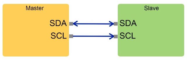
I2C is yet another synchronous serial protocol like SPI, but with several advantages over it. These include the ability to have multiple masters and slaves, simple addressing (no need for Chip Select), operating with various voltages, and using only two wires connected to two pull-up resistors.
⬤ Control LED by Serial Communication Tx & Rx
Interfacing two Arduino boards via UART protocol.
To understand how communication and networking work I start practice with two Arduinos by follow this tutorial Serial Communication Control LED Between Two Arduinos
Connection
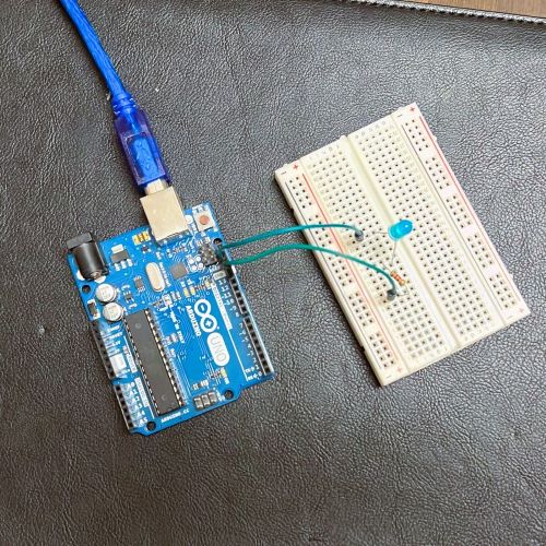
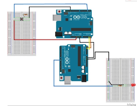
First I start prepare my first circuit with Arduino Uno, this one act as the Receiver.
- Arduino Uno
- Breadboard
- LED.
- 220 Ohm resistors.
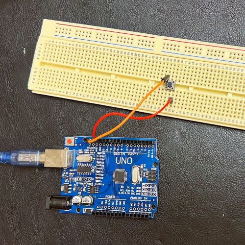
Second other circuit which is the push button circuit with Arduino Uno, this one act as the Transmitter.
- Arduino Uno
- Breadboard.
- Push button.
- 220 Ohm resistors.
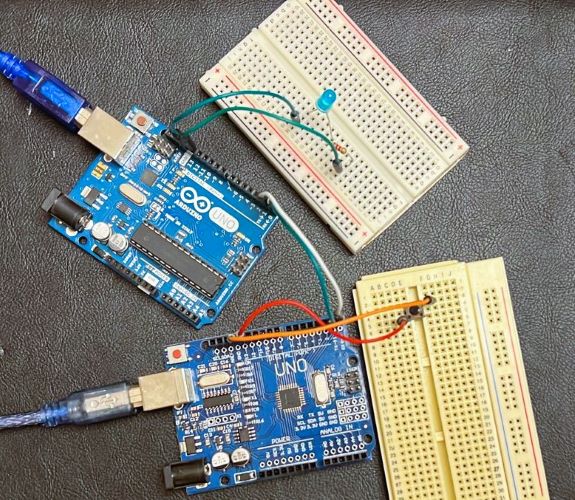
Connect the two Arduinos with wires going from TX to RX and RX to TX.
Code Explanation
Transmitter Arduino Code
First the “Transmitter” Arduino Code
pin 3 - Digital read from the button switch.
// Transmitter

int Button1 = 3;


void setup() {
// put your setup code here, to run once:

  Serial.begin(9600); // for communication
  pinMode(13, INPUT_PULLUP); // for read button


}

void loop() {
  // put your main code here, to run repeatedly:
  if(digitalRead(13) == 0)
  {
    Serial.write('1');

  }
  delay(20); // waitting message send
}
to send a signal when the button is pressed. It will then send a 0 or 1 to the Receiver, indicating whether to turn the LED on or off.
Receiver Arduino Code
the “Receiver” Arduino Code
pin 13 - Output to turn on the LED
int LED1 = 13;

char message;

void setup() {
  // put your setup code here, to run once:

  Serial.begin(9600); // communication
  pinMode(13, OUTPUT);


}

void loop() {
  // put your main code here, to run repeatedly:
  if (Serial.available())
  {
    message = Serial.read();
    if (message == '1')
    {
      digitalWrite(13, 1);
    }

  }
  delay(20); // waitting message reciev
  digitalWrite(13, 0);

}
The Receiver Arduino receives the signal from the Transmitter Arduino. The signal should be either a 0 or a 1. If it is a 1, it turns its LED on, and if it is a 0, it sends the signal to turn the LED off.
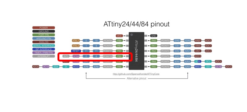
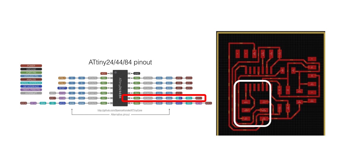
⬤ ATtiny44
After I understand the concept of networking and communication with Arduino now I can start work with my Circuit
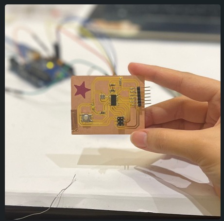
because I have an old board I worked on it in Electronic design with Attiny44 I plan to create a new board with Attiny44.
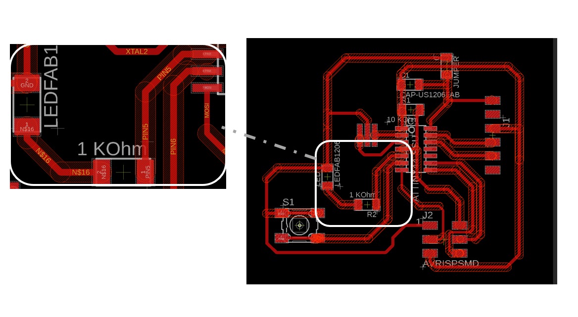
Schematic
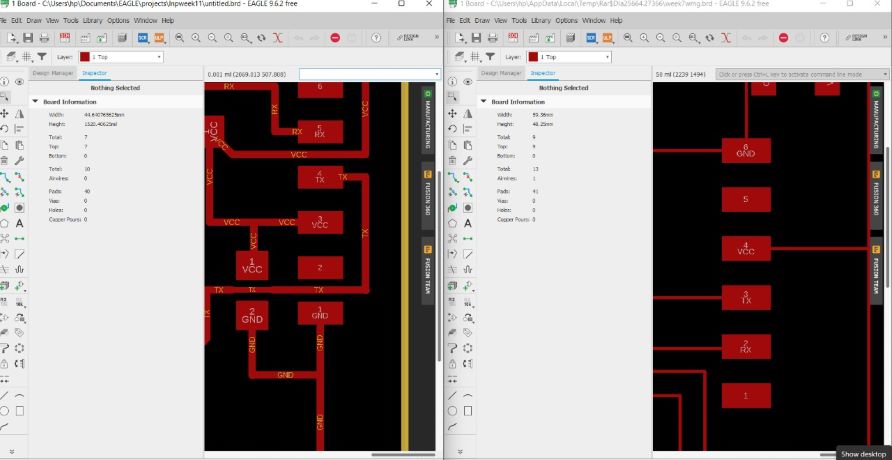
Designing the Circuit with eagle
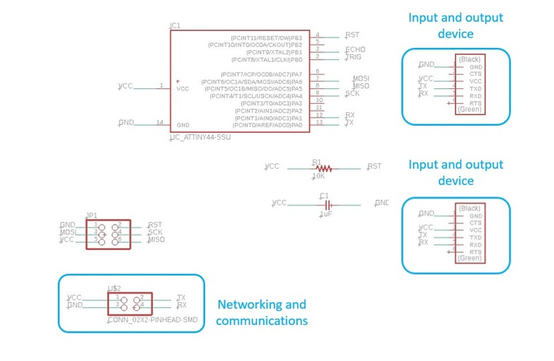
The first thing I do add all the necessary components for the hello-word board ATtiny 44 Echo Hello World board I design my PCB in Eagle. I create a new schematic, and add all the components , I want to use this circuit with a different project in the future so I add headers as you see in the picture above .
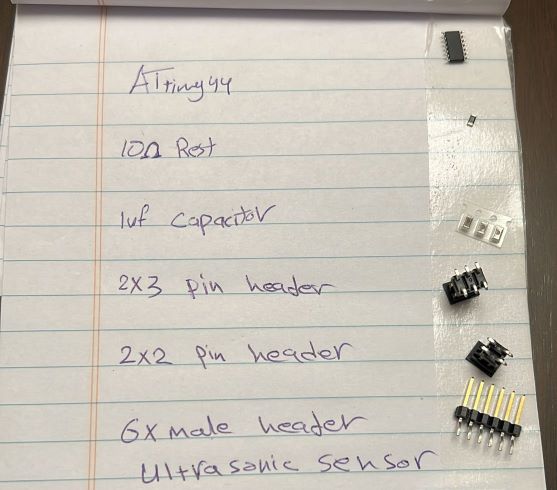
The electronic components that I used for this assignment are:
- 1 x ATtiny44.
- 2 x 10kΩ resistors.
- 1 x 499Ω resistors.
- 1 x 1uF capacitor.
- 1 x 2x3 pin header (ISP).
- 6 x Male headers.
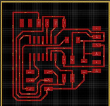
then I made all the connections, and create a board file from it,Then I export the images for the traces and outline into .png
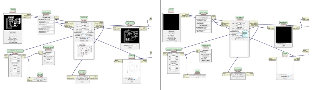
I got the .rml files through MODs and then I milled the PCB.
Millimg with Roland srm-20
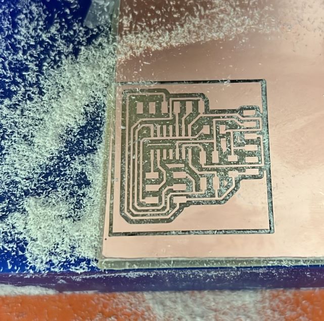
milled the PCB. This is my first time ,the milling part went quite smoothly, without any problems and the board came out nicely ☺ .
Soldering
To start soldering I prepare all the components I need which I mentioned or above.
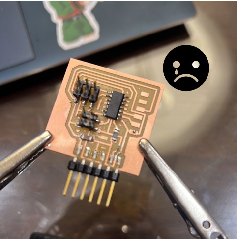
my happiness is disappear when I realize my PCB is very tiny and it’s so hard to solder the components I spent around 5 hours trying to solder it very well and test each component by multimeter
Burn Bootloader
Now I connect my board with Arduino and try to burn it
board manger > Add ATtiny
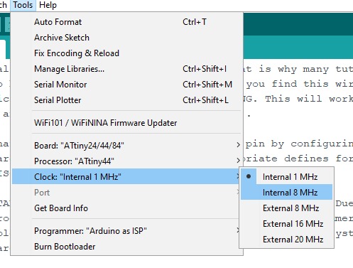
- board ATiny24/44/84.
- Processor ATTINY44.
- Clock Internal 8 MHz.
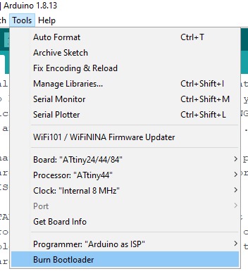
Tools > Burn Bootloader
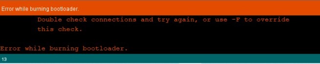
I got this Error several times and each time I check with the multimeter and find shorts until it’s successfully done.
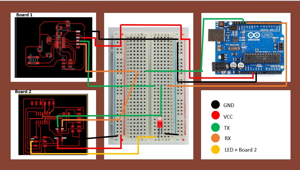
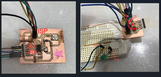
Connection
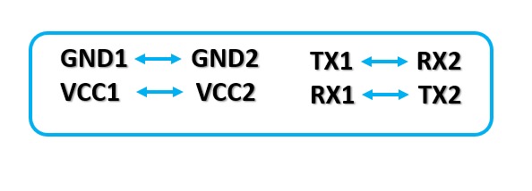
Now I connect the two boards following the diagram below. The most important thing here is that the pin that is going to send the information need to be connected to the one that will receive it, so TX and RX must be crossed.
I open the eagle files to be sure to follow the right pins I’m using my PCB I create it as A Transmitter board.
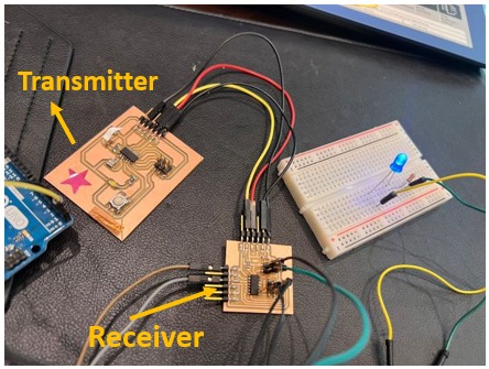
Here I connect my wires and upload my coding, my Idea was to control the LED BUT there is something wrong I did not understand it and I read and followed the steps again and again until I realize I have a good serial protocol but I messed up with the circuits, the LED turned ON but the button in the Receiver board does not work !!
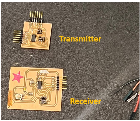
here is the problem my plan was to use the button from my old PCB to control the LED but this PCB is the Receiver because there are no extra RX, or TX pins it just can receive the data :)
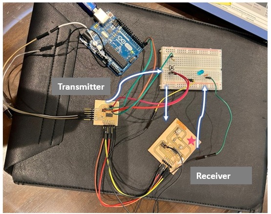
So I get help with a breadboard and bring an external button to connect it with the Transmitter PCB
now it works right the Transmitter board will send data to the button (If it’s (1) the led turn ON if it is (0) the LED will turn OFF) the Receiver board will receive the data.
Code Explanation
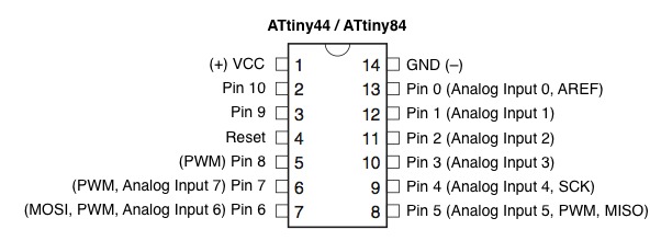
As I explain code the above with Arduino now I need to change the pins by following the data sheet of ATtiny44.
Transmitter code (Sender)
pin 6 in ATTINY44 - Digital read from the button switch.
// Transmitter

int Button1 = 7;


void setup() {
// put your setup code here, to run once:

  Serial.begin(9600); // for communication
  pinMode(7, INPUT_PULLUP); // for read button


}

void loop() {
  // put your main code here, to run repeatedly:
  if(digitalRead(7) == 0)
  {
    Serial.write('1');

  }
  delay(20); // waitting message send
}
Receiver code
pin 9 in ATtiny44 - Output to turn on the LED
int LED1 = 6;

char message;

void setup() {
  // put your setup code here, to run once:

  Serial.begin(9600); // communication
  pinMode(6, OUTPUT);


}

void loop() {
  // put your main code here, to run repeatedly:
  if (Serial.available())
  {
    message = Serial.read();
    if (message == '1')
    {
      digitalWrite(7, 1);
    }

  }
  delay(20); // waitting message reciev
  digitalWrite(7, 0);

}
Final result
⬤ Control LED by Serial Communication Tx & Rx
Interfacing two ATtiny44 boards via UART protocol
Using Arduino here as a bridge to send data to ATtines Upload Arduino code define 12/13 as RX / TX
#include <SoftwareSerial.h>

SoftwareSerial mySerial(12, 13); // RX, TX

void setup() {

  Serial.begin(9600);
  while (!Serial) {
    ;
  }


  mySerial.begin(9600);

  void loop() {
  if (mySerial.available()) {
  Serial.write(mySerial.read());
}
  if (Serial.available()) {
  mySerial.write(Serial.read());
}
}
Board No.1
Now I will try to send data from serial to my two ATtiny boards ,First of all, I will upload my code separately to each board, so for board No.1 the code will work when I send the number “1” to the serial monitor, and the build-in LED will turn ON.
By my following my shamanic LED is in pain 5 which is pin 8 in Arduino
ATtiny44 data sheet
I connect the Attiny ISP and TX/RX with Arduino to upload the code (TX & RX crossed)
#include <SoftwareSerial.h>
SoftwareSerial mySerial(PA1,PA0); //RX, TX
int v=0;
int nodeid=1; //the id
#define led 8  // the led pin
bool ledStatus=0;  //the status of the led


void setup() {
  Serial.begin(9600);
  pinMode(8, OUTPUT); // white led
}

void loop() {
  while (Serial.available () == 0 ) {}
  v = Serial.parseInt();
  Serial.println(v);
  if(v == nodeid && ledStatus ==0 )
{
  digitalWrite(8,HIGH);
  ledStatus=1;
}
else if (v == nodeid && ledStatus ==1 )
{
  digitalWrite(8,LOW);
  ledStatus=0;
 }
}
Board No.2
now board No 2 I upload the code when I send 2 to the ATtiny the LED will turn ON (here I’m using bread board the LED pin is 9 in Arduino is 6 as the picture explain)
I connect the Attiny ISP and TX/RX with Arduino to upload the code (TX & RX crossed)
#include <SoftwareSerial.h>  //
SoftwareSerial mySerial(PA1,PA0); //RX, TX
int v=0;
int nodeid=2; //the id
#define led 6  // the led pin
bool ledStatus=0; //the status of the led


void setup() {
  mySerial.begin(9600);
  pinMode(6, OUTPUT);
}

void loop() {
  while (mySerial.available () == 0 ) {}
  v = mySerial.parseInt();
  mySerial.println(v);
  if(v == nodeid && ledStatus ==0 )
{
  digitalWrite(6,HIGH);
  ledStatus=1;
}
else if (v == nodeid && ledStatus ==1 )
{
  digitalWrite(6,LOW);
  ledStatus=0;
 }
Two boards (ATtiny44) Communicate
I’m using the breadboard this time because board No 2 did not have a built-in LED, I create my own diagram to understand how it works So if I send 1 the LED board number one will turn ON, if I send 2 to board number 2 the LED will turn ON.
¬ ¬
Final result
Useful link
files
Control LED by Serial Communication Tx & Rx
Control LED by Serial Communication Tx & Rx (Send data)