Electronics Design
Assignment:
Group assignment:
use the test equipment in your lab to observe the operation of a microcontroller circuit board.
HereIndividual assignment:
redraw an echo hello-world board, add (at least) a button and LED (with current-limiting resistor), check the esign rules, make it, and test it.
Building the first hello board
The objective of this week is to learn how to design and program a circuit board based on an echo hello-world board
Steps to produce the hello-world board
To design my first hello-world board, i had to first, read the data sheet of the microcontrollers and understand the structure, then do the following steps:
-Design the PCB using Eagle.
-Extract the images of the PCB and edit them.
-Generate The G-Code using Fabmodules.
-Mill the board.
-Weld the components.
-Write the code and upload it to the board.
-Test the board.
Re-drawing the echo hello-world board
I re-created the echo hello-world board and added an LED and a push button to activate the LED.
The original echo hello-world board contains the following components:
ATtiny44A microcontroller
1uF Capacitor
10 Koum Resistor
Resonator 20MHZ x 1
FTDI Pin Headers
ISP Pin Headers
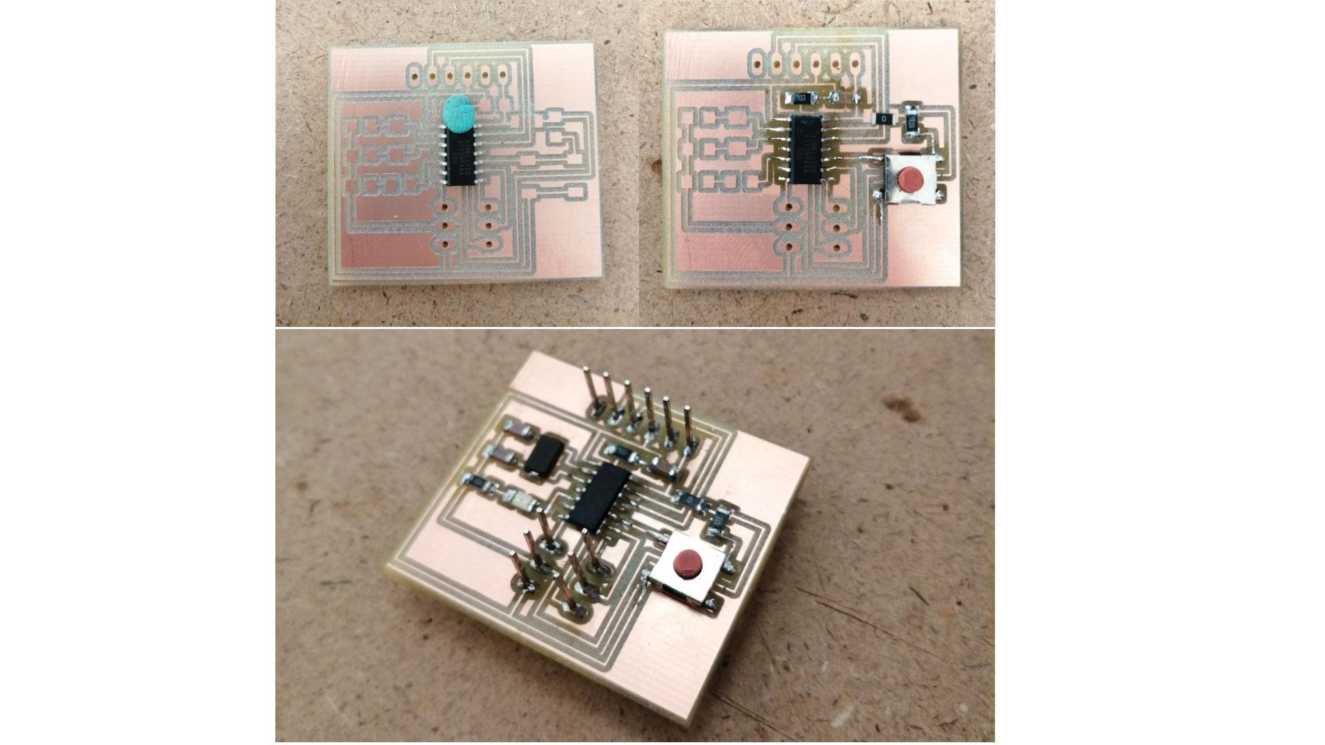
My echo hello-world board
I placed a crystal and 2x pf capacitors instead of the resonator, and i added a push button and an LED. So, my components are:
ATtiny44A microcontroller
1uF Capacitor near to the power input to filter out any excess noise.
2x 10K ohm Resistor one between the reset and vcc ports, and the other for the push button.
crystal 20MHZ To ensure an accurate clock frequency for the microcontroller.
2x 1pf capacitors are needed for the crystal to oscillate.
FTDI Pin Headers
ISP Pin Headers
1x RED LED
1x Push button
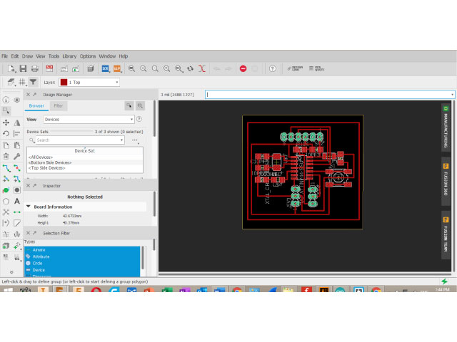
Designing the PCB
I used EAGLE to design my board. First I opened EAGLE , started a new Project and created a new Schematic.
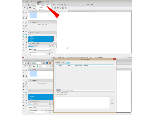
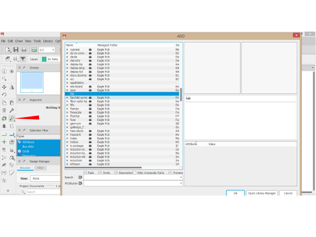
The first step to begin with eagle was to download the fab library which contains all the required SMD components we will use for the board for eagle. then open library manager and choose the downloaded library.
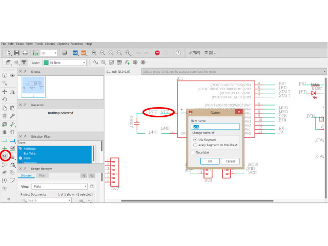
After that i started placing my components by first placing the ATTiny44. After placing all components, i started connecting them together.
The ATTINY44 MCU
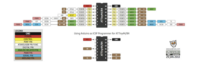
The MCU (MicroController Unit) Attiny44(in our case) has a default pin configurations
After reading the data sheet, I gathered the following information about the ATTINY44:
Operating Voltage Range: 2.7 -5.5V
Pin 5 for is for output, Pin 6,10,11 are for output and input
Internal Clock of 8 Mhz
In my design, I used pin 5 as an output, to control the LED. And I used pin 10 as an input to recieve data from a push button.
The ISP connection is to program the board and the FTDI connection is to link it to the PC serial port
After finishing, i extracted the images following the steps below. I used photoshop to edit my images.
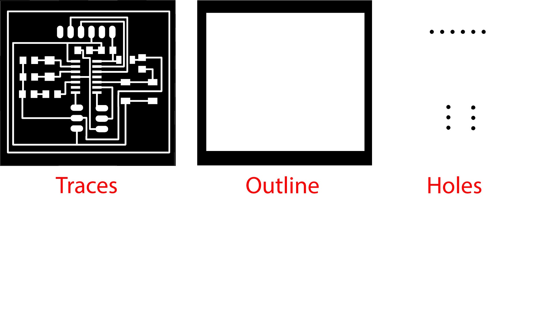
To extract the traces from eagle, we go to view -> layers, and then we turn off all layers and we keep the layers that we want.
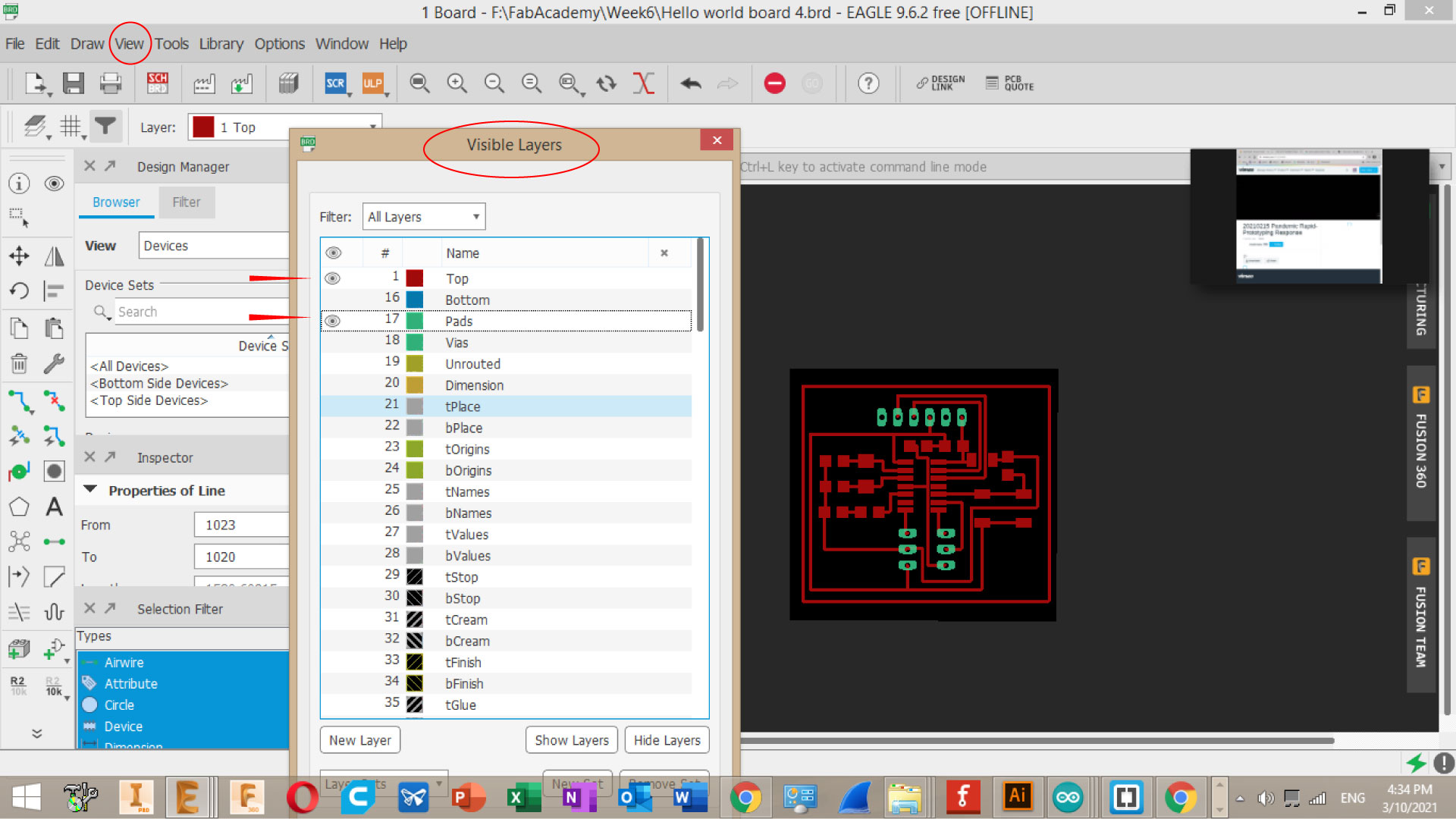
Then press on Export as, and choose as an image,
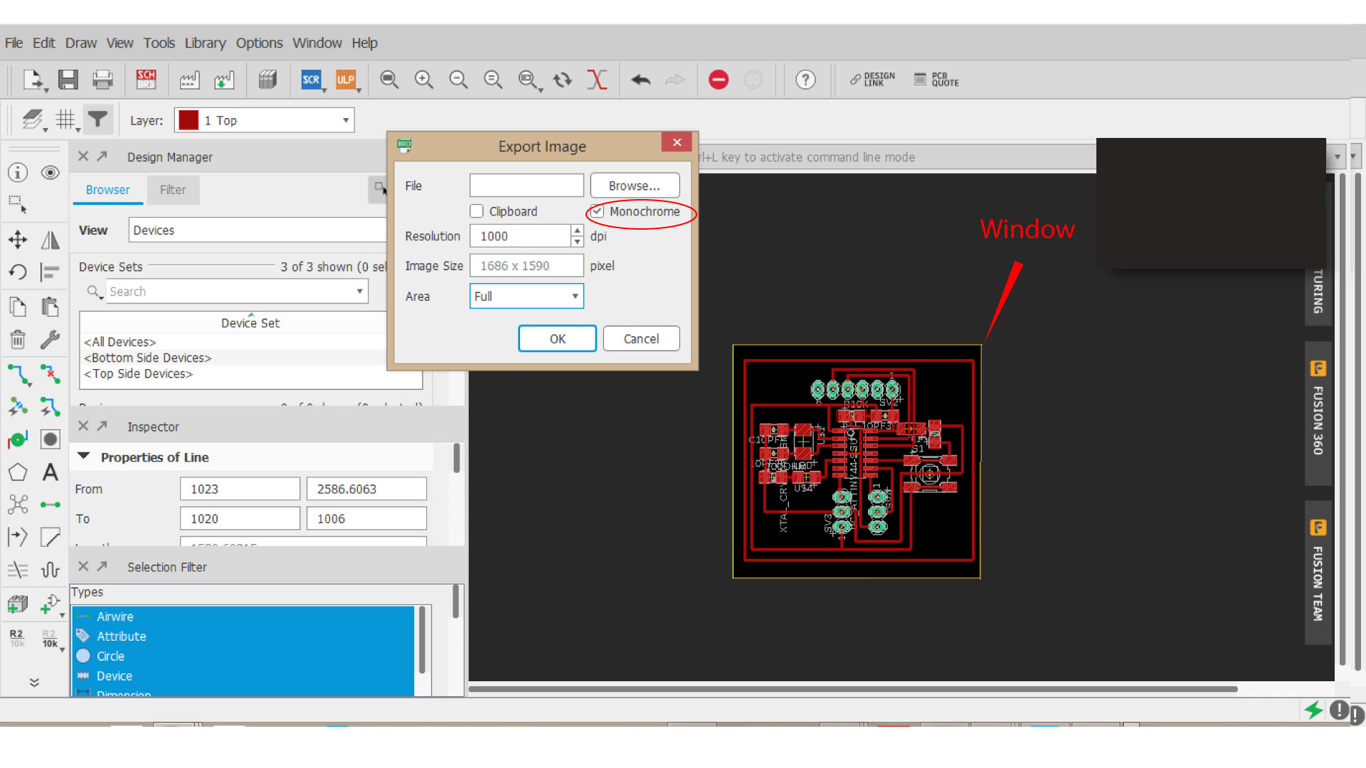
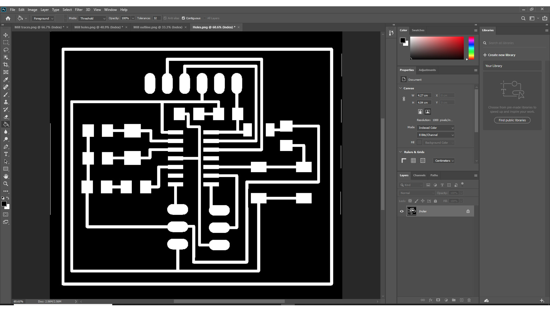
One mistake I made was that I did not remove the edges in the traces image, so there was an extra area that was cut and we did not need to cut it. note that the machine will mill the black areas and keep all the white lines.
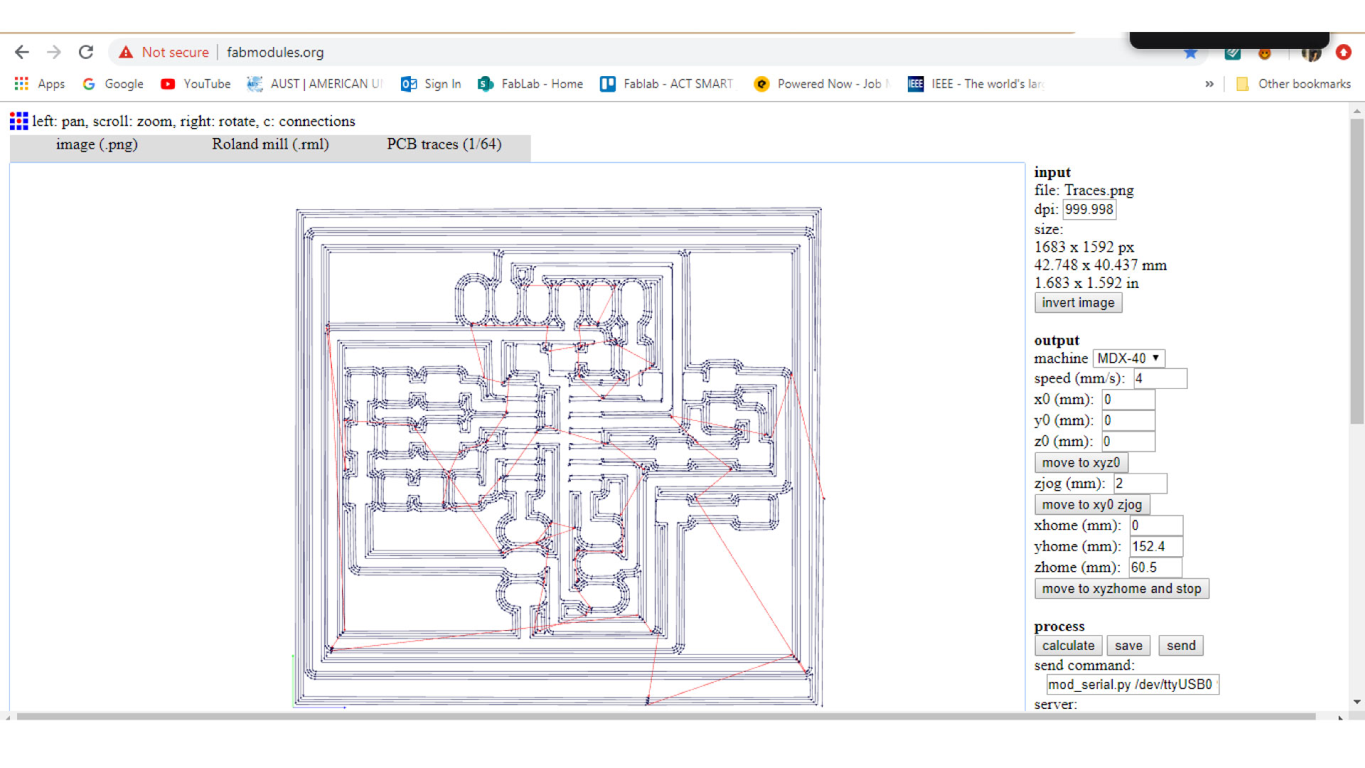
Then, I used Fabmodules to generate my G-code.
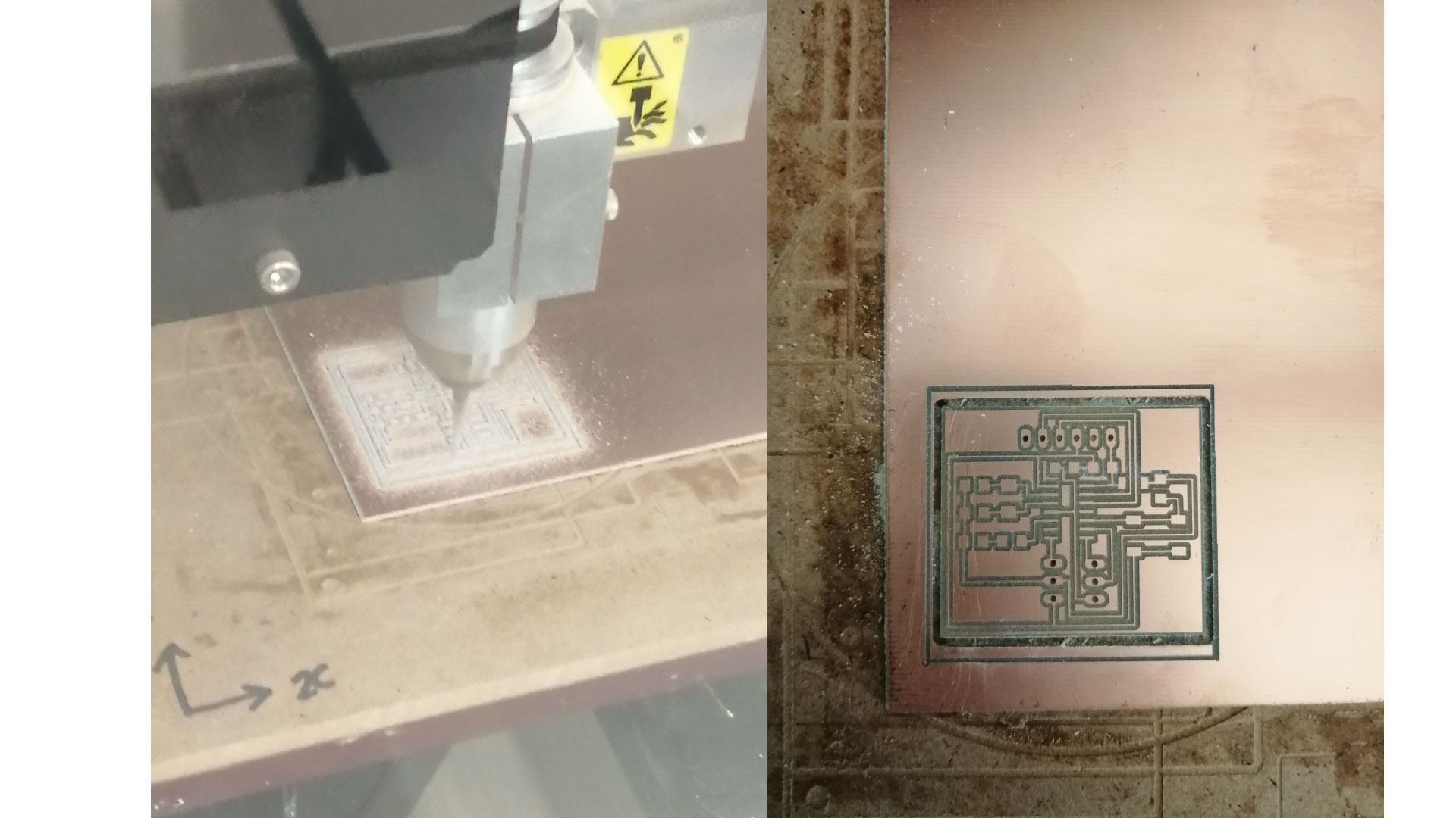
Milling the board
I used a 0.4 mm bit to make the traces of the pcb, and a 0.8 mm bit to drill the holes, and a 1.2 mm bit to cut the outlines.
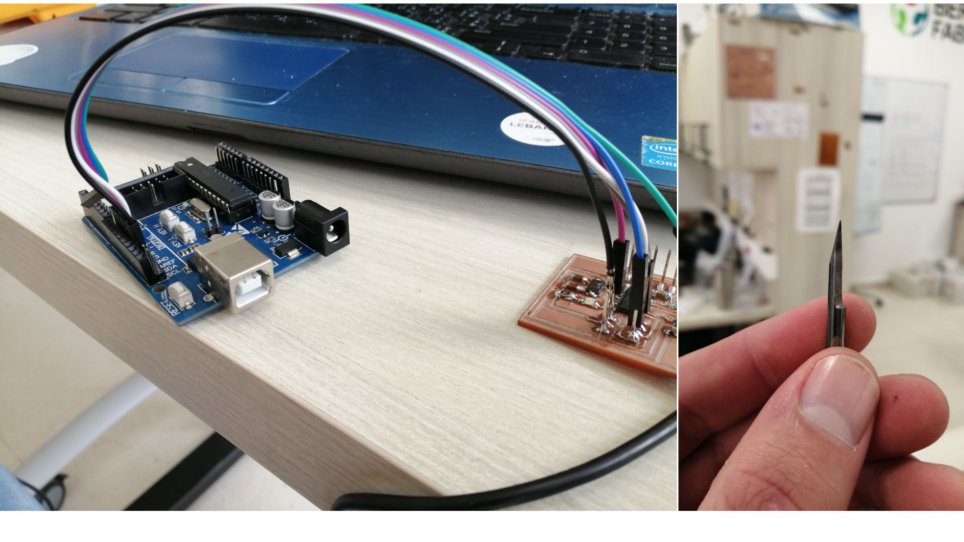
After that, when the board was ready, I started welding the components on the board. In my first trial, I added too much TIN (soldering material) to the components, and that caused the copper to come out at some areas. And i tried to upload my code to the board but it did not work, so I went to mill another board, Unfortunately, while I was milling the new traces, the head of the 0.4 mm bit was broken, after investigating the reason behind that, it turned out that the bed is not completely flat and some areas are a little higher than the other, and when I zerod the Z-axis, i went down a little bit more.
So I used another bit and made sure the surface is flat and the Z-zero is not too deep, and i milled another board.
Programming the board
Now that we have all our components ready, we want to program our micro controller using the Arduino IDE.
First, we connect our board to the Arduino following following the image below.
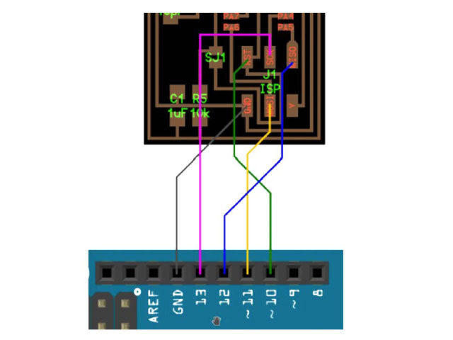
GND to GND on Arduino, RST to Pin 10 on Arduino, MOSI to Pin 11 on Arduino, SKC to Pin 13 on Arduino, VCC to VCC on Arduino, MISO to Pin 12 on Arduino.
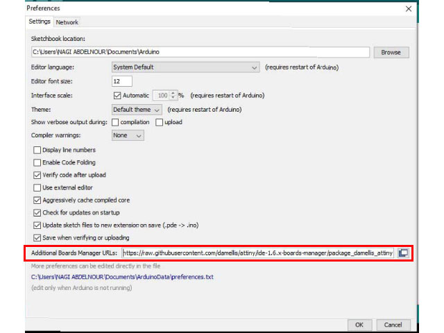
Then, we start Arduino IDE. We want to choose our board to be the ATtiny45, to do so, we want to add a link for the ATtiny in the board manager.
Go to File > Preferences then, in the Additional Boards Manager URLs add the following link ( https://raw.githubusercontent.com/damellis/attiny/ide-1.6.x-boards-manager/package_damellis_attiny_index.json )
Then, go to Tools > Board > Boards manager and type ATtiny in the search bar, and download it.
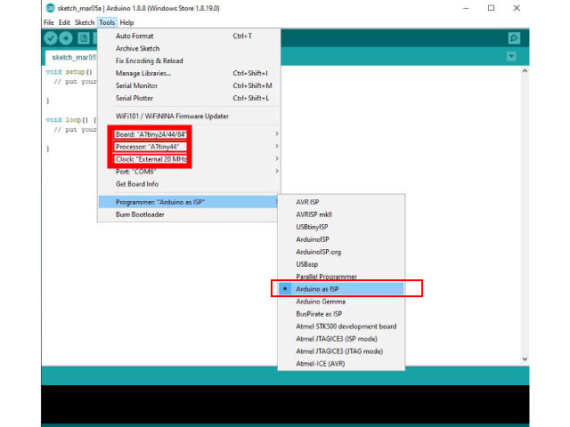
For the first time, we want to burn bootloader by pressing the bootloader under tools.
Now we want to program our board. But first, we want to know the indication of the pins we used in arduino IDE.
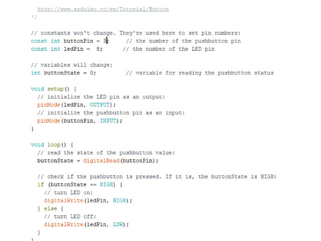
We can also manipulate the code a little bit to do something different than just blinking the light once.
