3D scanning and printing - 05
Assignment:
Group assignment:
test the design rules for your 3D printer(s)
Individual assignment:
Design and 3D print an object (small, few cm3, limited by printer time) that could not be made subtractively.
3D scan an object (and optionally print it).
Introduction
Additive Manufacturing, also known as 3D Printing, refers to a range of layer-upon-layer manufacturing technologies, used to Build a three-dimensional object both for prototyping and manufacturing purposes. The process involves the successive forming of material layers under computer control, allowing complex components to be manufactured.
Types of 3D printers
Different types of 3D printers are ranged depending on the output quality and level of details wanted. There are different 3D printing techniques like FDM (Fused-Deposition Modeling), SLA (Stereolithography) or SLS (Selective Laser Sintering) with their own unique features that can be used for prototyping.
Production process
Step 1 - Design your object – our download open-source designs
Computer Aided Design: Autodesk Fusion 360, Solidworks, Rhino and Catia are some of the 3D modeling software that can be used to design parts for 3D printing. GrabCAD, cults3D, all3Dp, and thingiverse are some of open source sites to download 3D models.
Step 2- Prepare the Production Files
Input Format: The input file that we want to send to the 3D printer should be saved in (.STL) format.
Step 3- Preparing the job
Slicing: a slicing software such as Cura or Preform is needed to prepare the machining job. In this software, you choose the best setting that you need based on the quality of the object you want to produce. The slicer will then generate the g.code, digital commands that will guide the machine during the production process.
Step 4 – Send your file
In this step, the g.code is uploaded to the machine
Step 5 – Remove and Post Processing
Remove the printed object from the 3d printer and do some cleaning to the parts if needed.
How 3D printers work
FDM 3D printing
Fused deposition modeling (FDM) is a 3D printing process that uses a continuous filament of a thermoplastic material. Filament is fed from a large spool through a moving, heated printer extruder head, and is deposited on the growing work. The print head is moved under computer control to define the printed shape. Usually the head moves in two dimensions to deposit one horizontal plane, or layer, at a time The work or the print head is then moved vertically by a small amount to begin a new layer. There is a variety of 3D printing filaments to choose from. PLA and ABS filaments are mostly used in FDM 3D printing. What affects the choice of material is the application of the print since each material has its own properties.
Some definitions in FDM 3D printing
Infill: Infill density is the amount of material printed inside the object, it is chosen depending on the strength needed, weight, and application of the print. Infill also affects the timing of the print, for instance, if we choose 100% infill we will have a full solid, and if we choose 0% infill our object will be hollow from the inside. Infills can also be in different patterns, they can as well affect the timing
Wall Thickness: to choose how thin or thick we want our walls to be. It can also affect the timing, quality, and level of detail of the print.
Layer height: it affects the final print than quality. If chosen properly, this setting will increase your print’s speed, resolution, and smoothness.
Supports: Supports are not a part of the printed object, but they are crucial for 3D printing, without supports we might have parts of the print hanging and falling down. The printer builds the supports in thin layers to be removed easily when after finishing.
Build plate adhesion: Skirt, brim, or raft, are options for build plate adhesion. They are needed to keep the first layers of the print from wrapping and lifting off the 3D printer bed.
SLA 3D printing
Stereolithography (SLA) is another 3D printing process where an object is created by selectively curing a polymer resin layer-by-layer using an ultraviolet (UV) laser beam. SLA 3D printers use a variety of specialized engineering materials and produce smooth, isotropic parts that are strong and highly detailed. A model is created one layer at a time as a laser beam moves across a bath of liquid resin. The laser's movements are guided by a 3D CAD program. SLA enables a model to be made with high resolution because each layer can be very thin. This means that handwork to finish the part is less than with other rapid prototyping technologies. The variety of materials for SLA 3D printing depends on the application of the Print. Some of these materials are Rigid, flexible, clear, high temperature, dental and castable wax resin.
Applications
3D printers are ideal to create complex models, turning a computer file into a physical prototype. FDM 3D printing can be used to make Artistic Shapes or Functional Parts for Working Prototypes and projects, usually in plastic material. Project can be gears, robotics arms, joystick parts and anything else. It can also print artistic stuff like vases, toys, accessories, jewelry, fashion, etc. SLA 3D printing can be used to make prototypes with high precession, artistic prints, jewelry and fashion, and many medical applications. It can be also used in the medical field to prototype new medical products.
3D printer test
Our assignment for this week was to test the design rules of our 3D printers, to do so, we downloaded open source 3D models that include multiple complex shapes to check possible problematic printing/slicing stuff that can be faced.
We used the Ultimaker 3D printers to test.
The test:
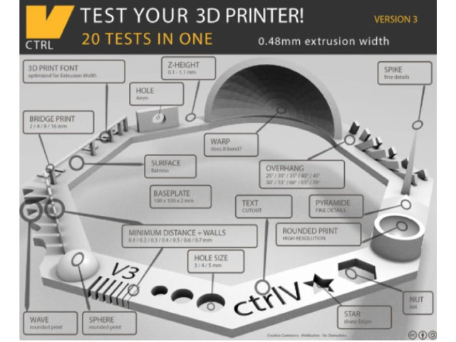
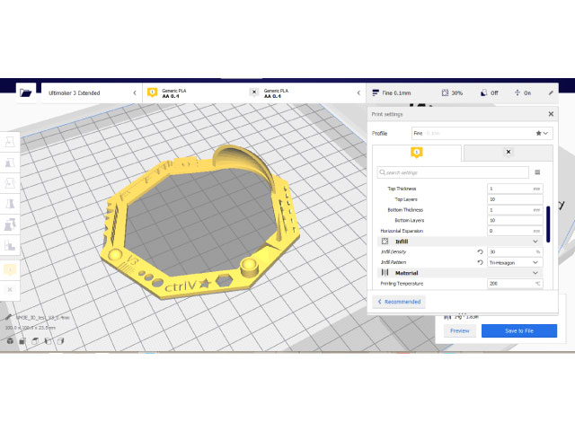
This 3D printer testing model was downloaded from the thingiverse. This test was performed on an Ultimaker 3D printer, and Cura was used as a slicing software to prepare the file.
Settings:
• Layer height: 0.1 mm
• Wall thickness: 1 mm
• Infill: 30%
• With raft
• Without supports
Results:
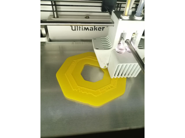
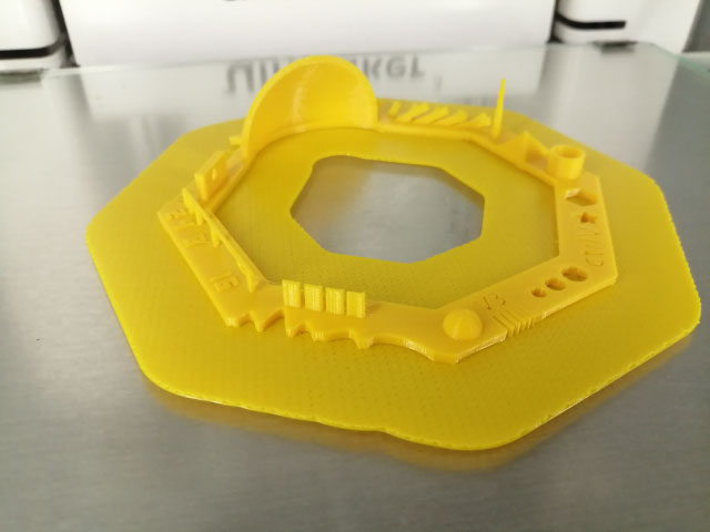
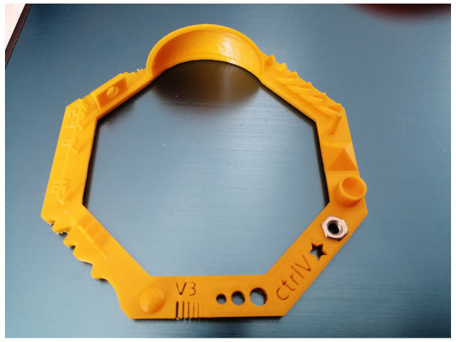
M4 nut fits perfectly.
Font is not distorted.
Hole sizes: 4.9, 3.9, 2.9.
Star with sharp edges.
minimal Distance that can be printed: 0.3 mm and above.
Z height: 0.4, 0.5, 0.6, 0.7, 0.8, 0.9, 1.0, 1.1 mm were fine, it starts failing at 0.3mm, and it does not print 0.1mm
09 Bridge Print: 2, 4, 8, 16 mm, material starts hanging at the end of the 16mm bridge. Finest bridge was between 4 and 8mm.
Sphere Mix, 7 mm height, which matches the test.
Pyramid, 7 mm height, which matches the test.
Overhang: if we go above 65°, there will be hanging parts.
Hole in Wall, 4 mm diameter, which matches the test.
Did not have a spike.
The waves came rounded.
It did not wrap.
Test 2
Settings:
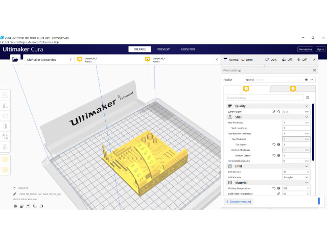
• Layer height: 0.15mm
• Wall thickness: 1mm
• Infill: 20%
• Without supports or brim
Results:
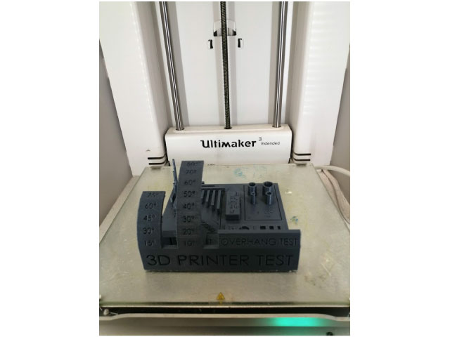
• Hole size (3 holes 4/6/8 mm): Good precision
• Diameter Test (1 mm wall): 4 tubes 4/6/8/10 mm: Good precision
• Support Overhang Test (10°/20°/30°/30°/40°/50°/60°/70°/80°): Below 60 good quality above 60 passing quality.
• Bridging print (2/5/10/15/20/25 mm): Good quality
• Surface (all the flat parts): Good
• Pins test: 2 mm x 10 mm – 2 mm x 20 mm – 2 mm x 30 mm: passing quality
Design and 3D print an object
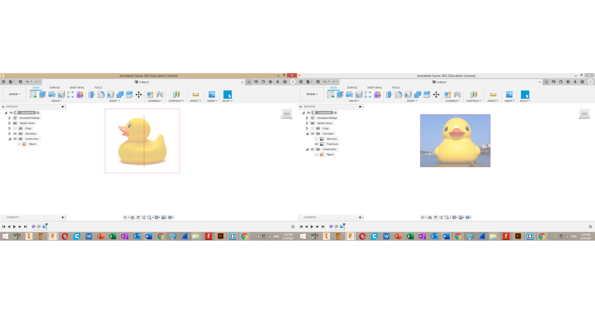
For This assignments I decided to model a duck-shaped snowball maker. I usually design mechanical parts, so this was my first time modeling using the form feature.
I started by placing side-view, front-view, and top-view pictures of my desigred model, and then I created a form and started shaping it to match my desigred shape.
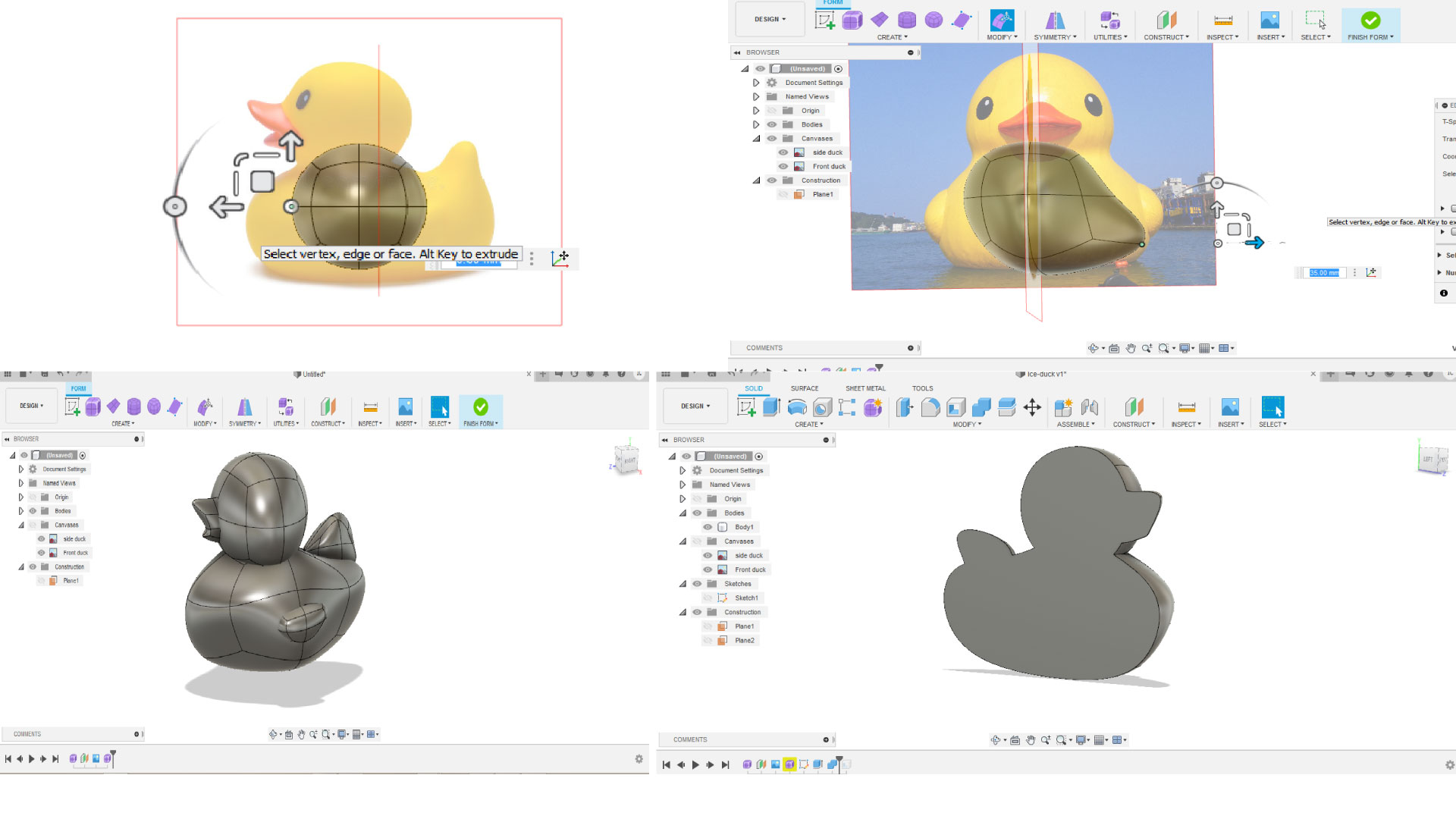
After I was satisfied with the result, split the model in half, grouped all its parts, then used the shell feature to make the shape hollow from the inside with 2mm thick walls.
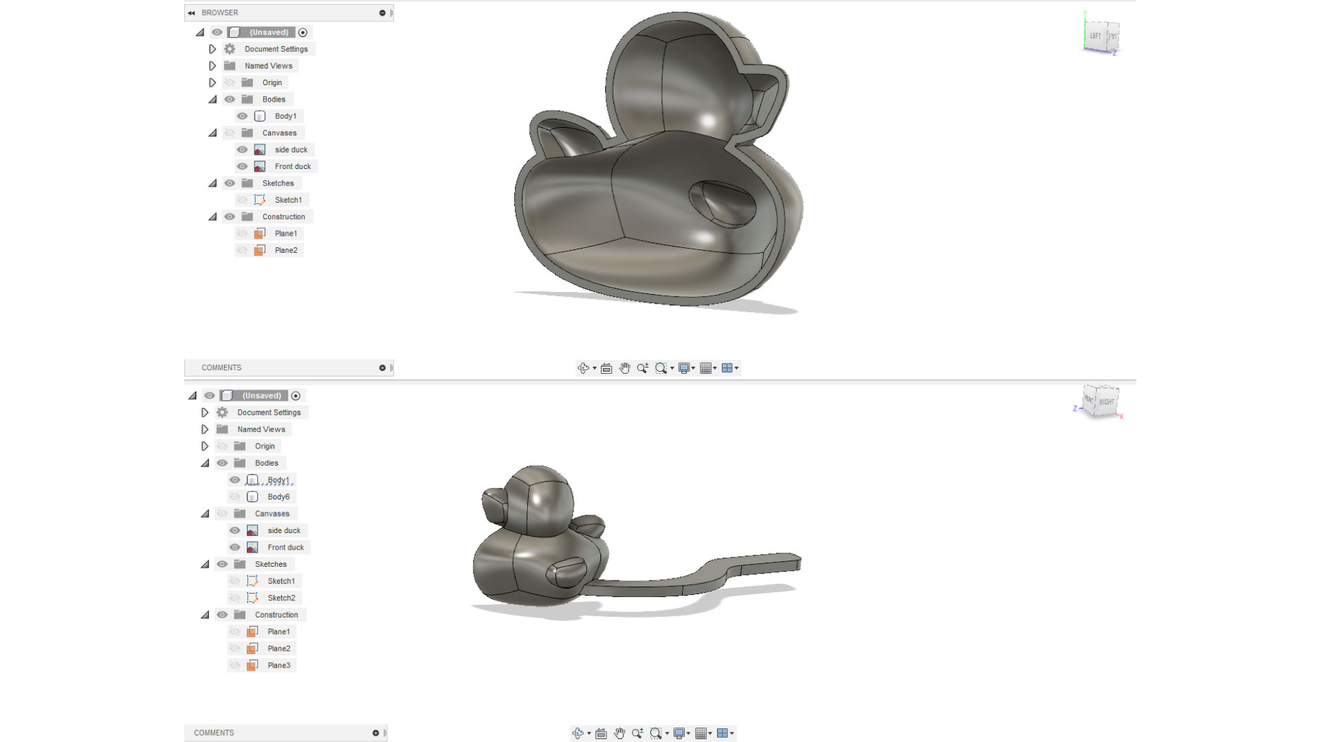
Then, I added the handles to open and close the model, and i made a joint for the handles. it was my first time creating a 3d printed joint so i wanted to try it.
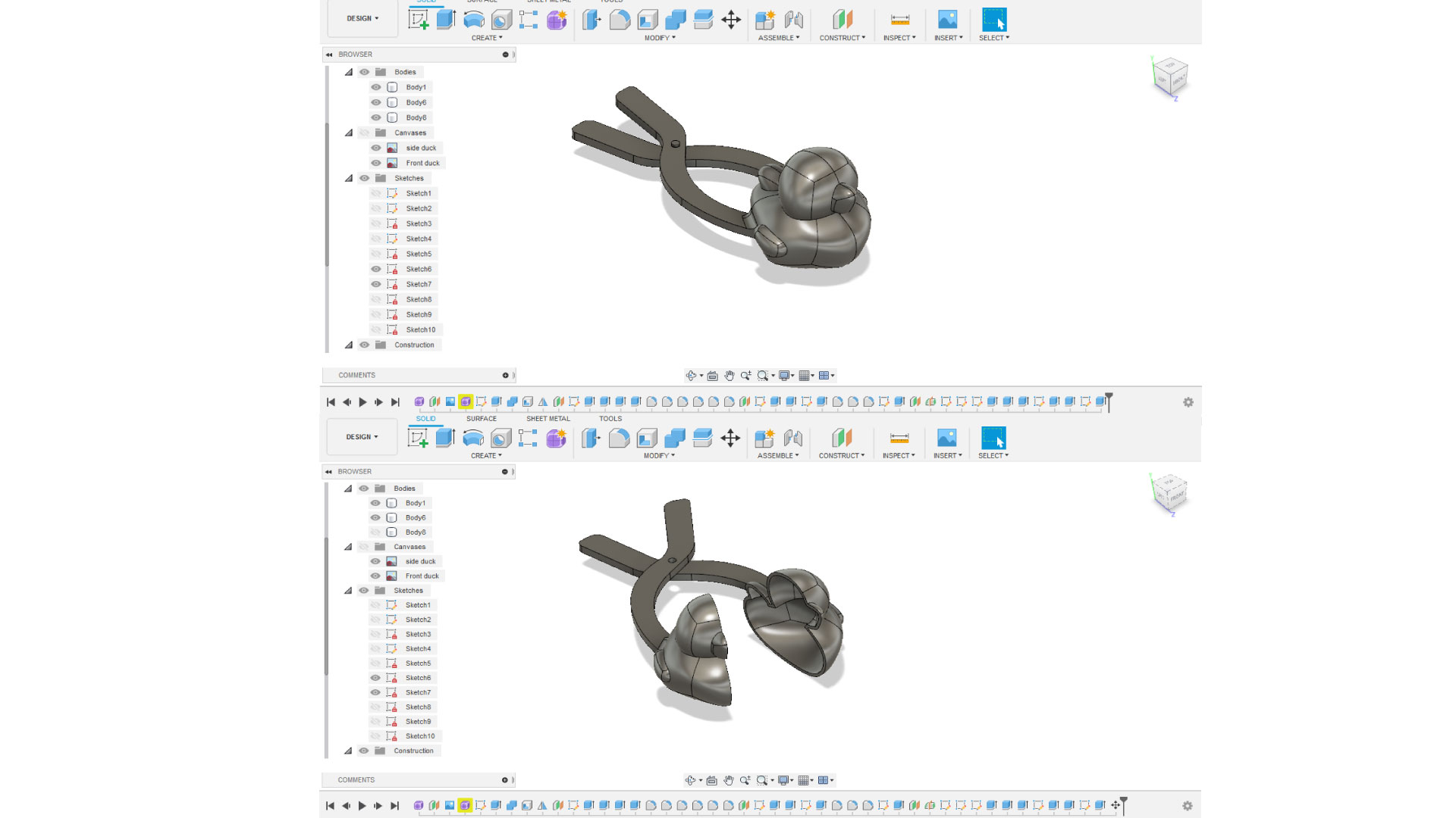
After that, I opened Cura to generate the G-code. Some of the settings I chose were 20% infill, supports enabled, brim enabled
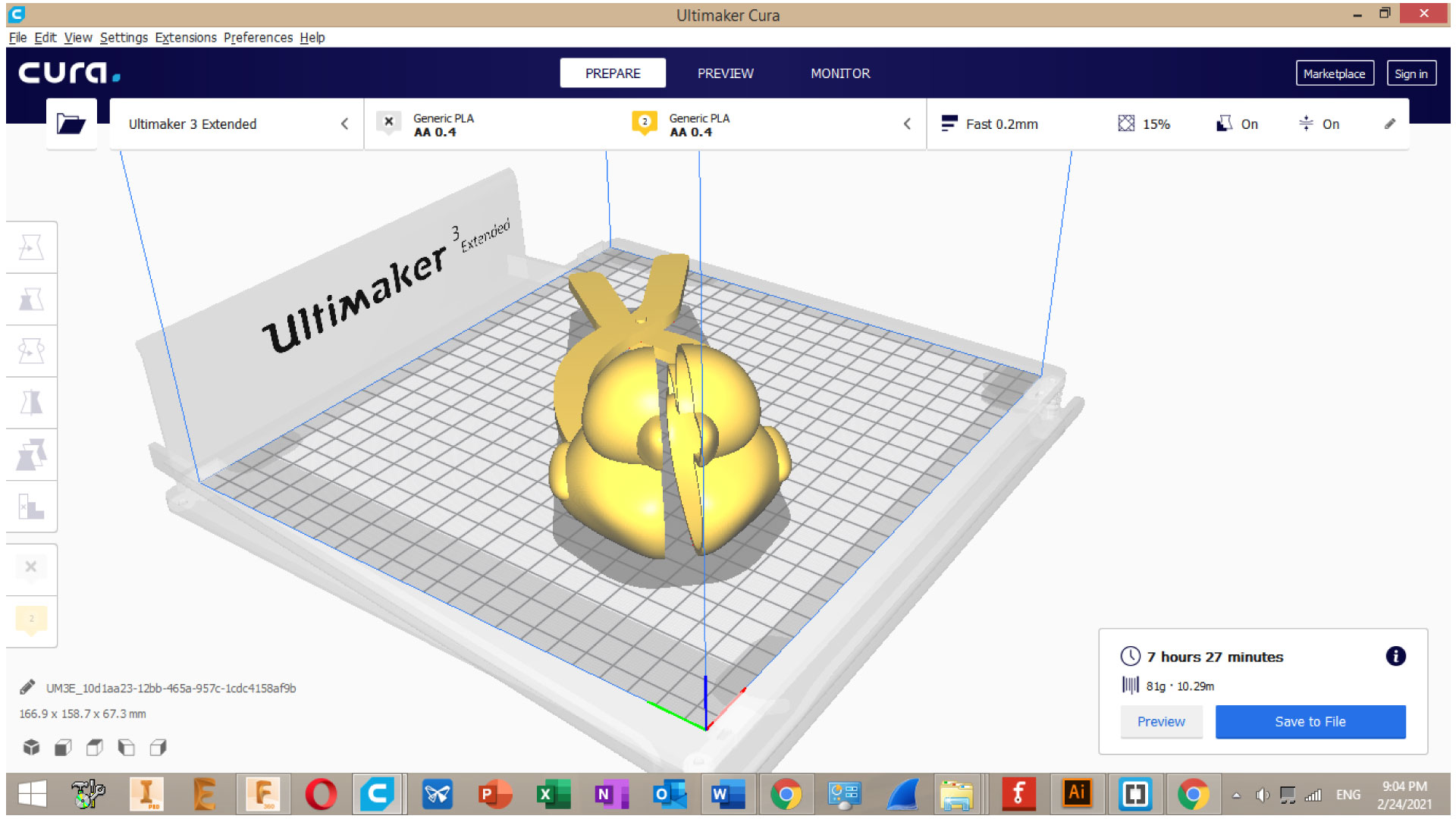
I placed my model in this orientation because of the joint I designed for the handles, it is not the ideal orientation since it consumes alot of suupports.
Once all settings were selected, We press slice to estimate the material amount needed, and print time. then we plug the USB of the 3D printer to the PC, and we save the G-code to the usb from Cura, then we eject the usb from Cura.
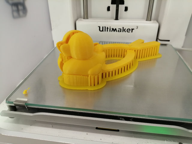
When it was done, i took the 3D model out and I removed all the supports.
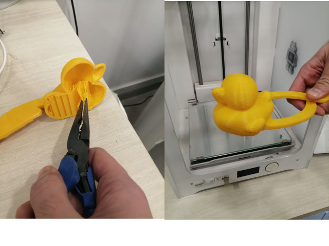
Unfortunately, the joint broke when i was sanding the surface of the duck, so I edited my design to make the joint wider, and I placed a screw with washers and a nut instead of the broken joint on my design.
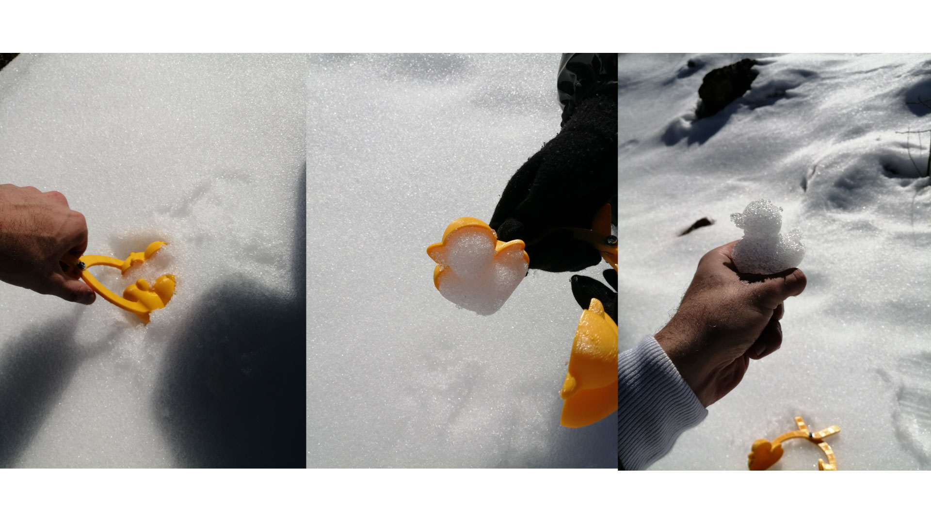
And here are the results!
3D Scanning
How does the 3D scanner work?
The 3D scanner we have in our lab uses the structured light technology for 3D scanning. Structured light scanning is a 3D scanning technology that uses light sources to projects multiple lines on the object, these lines are tracked by two cameras. Alternating stripes of light are projected on the object. the change of drop between one stripe and the other allows the camera to know the different depth in the object. The object should be scanned from all angles to get accurate meshes.
I decided to 3D scan a moon shaped lamp, i find it hard to design since it has many details on its surface, so 3D scanning solves that.
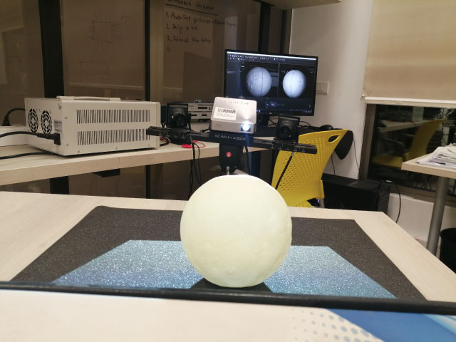
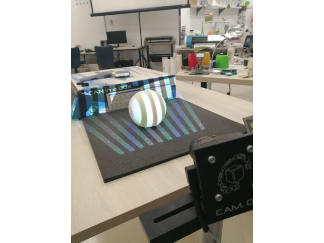
The 3D scanner can detect matt white object easier that other colors, so if the desigred object is hard to be detected, it is preferred if it was painted white.
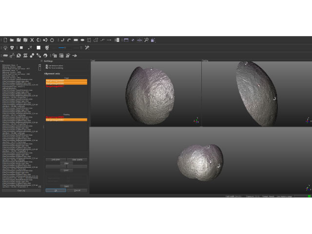
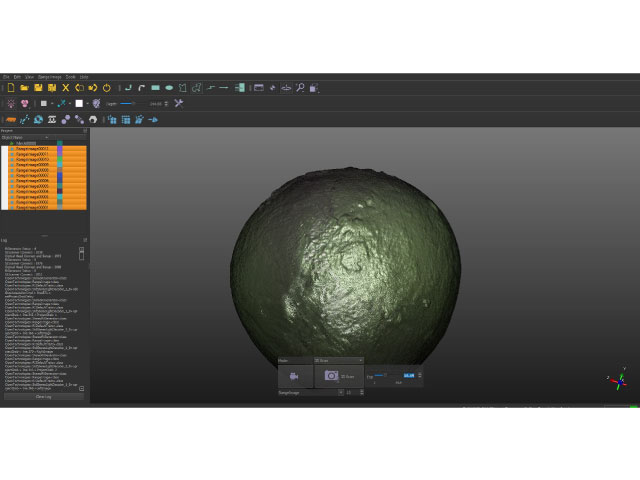
I started by plugging in the 3D scanner to the PC by connecting the two cameras to the USB ports, and the light source to the HDMI port, then i ran the software called IDEA that is used for scaning, and connected the scanner to it by pressing on the button that resembles the scanner, then scan the object from all angles, turn it around 15 degrees each time. When all sides are scanned, we then start joining the similar points between each two scans until we have the final shape. At the end, we generate a mish from our scanned surfaces and that mish is the 3D model that can be 3D printed or used in different designs.
The hardest part of the scan was to match the points between the scans, putting marks on the object could be a great help
