Electronics production - 04

Objective of week 04:
1-Characterize the design rules for the pcb production process
2-Understanding the settings and prcedure of the PCB milling machine
To understand the different settings and procedure to use the CNC milling machine. Many different settings can affect the process. The Variables are:
-The diameter of milling bit Different milling bits with different diameters can be used.
-Feed rate The rate in which the milling bit moves on the surface, milling small depths requires normal feed rates. However, to cut the outline of the board, higher feed rates are required.
-RPM The rotational speed of the milling bit.
-Offset number this variable controls the number of passes around the lines.
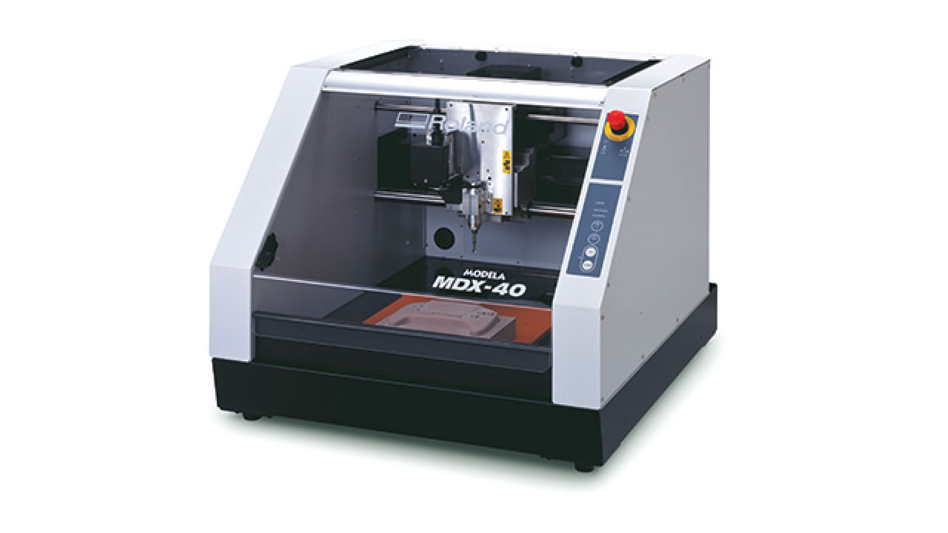
Machine used: Roland MDX-40
1- Group assignment: Characterize the design rules for the PCB production process
2- Individual assignment: Make an in-circuit programmer by milling and stuffing the PCB
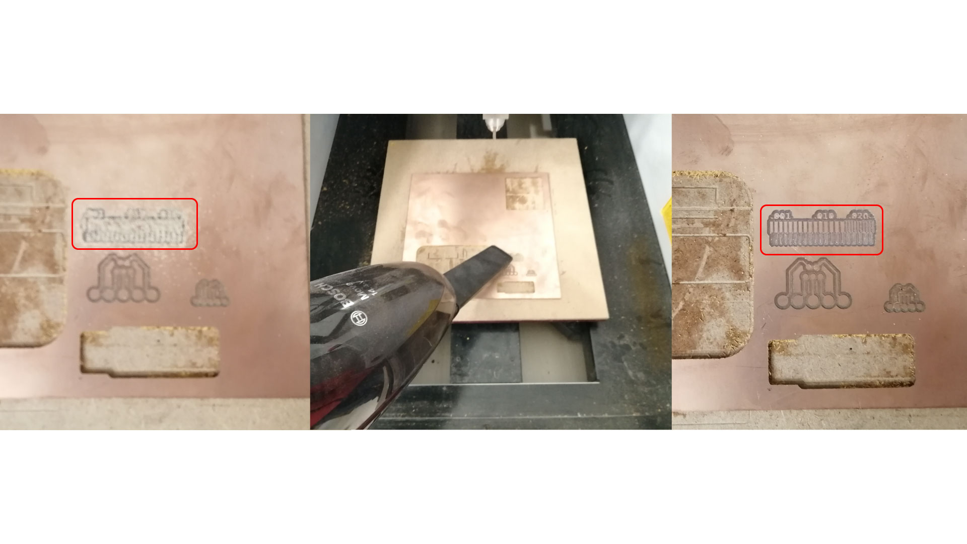
We started by preparing the test file, which is a downloadable image (can be downloaded from here ), it has different paths with different thicknesses. Before preparing the image, we have to understand that the machine cuts the black areas. To prepare the file, open illustrator (or any photo editing software of your choice), we want to remove the outer white borders
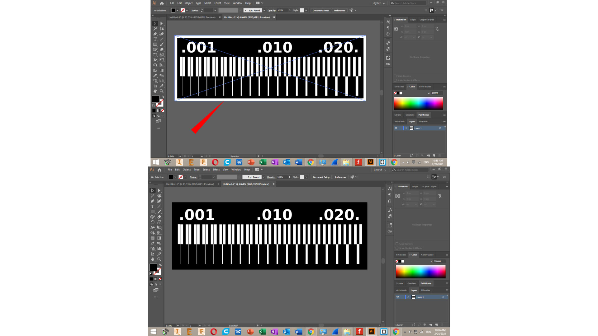
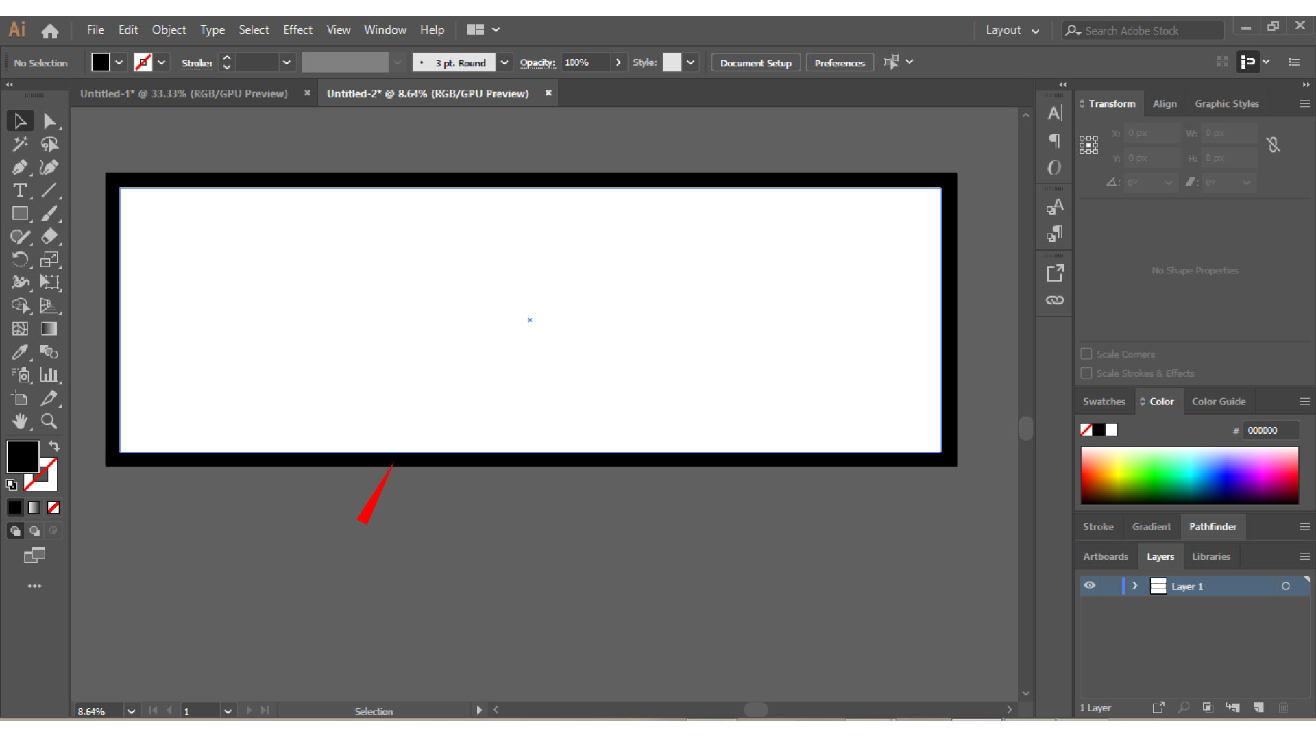
This image will be used to mill the internal traces, as for the external cutting path, we will have to prepare another image, by keeping the borders blacked out only
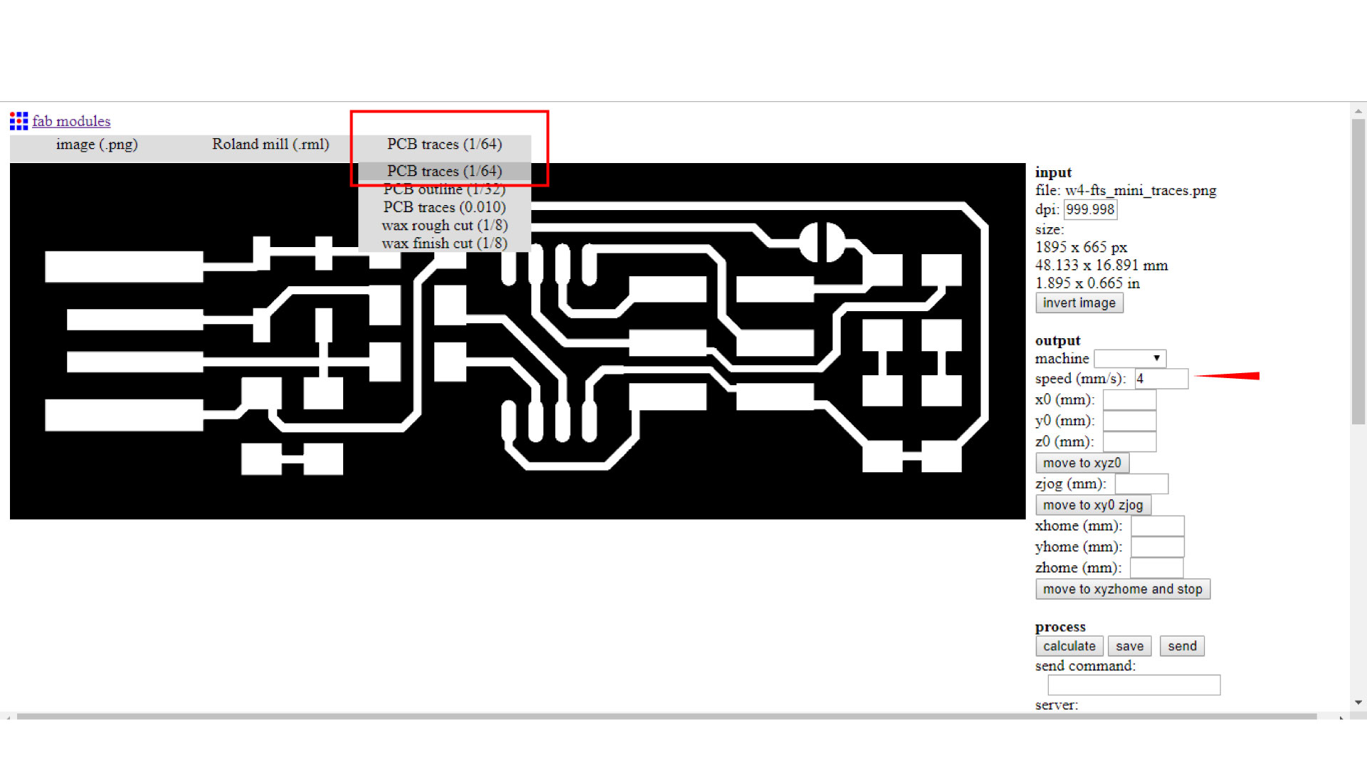
Now that we have the photos ready, we want to generate the G-code using fabmodules, then in fab modules we go to image > Roland mill > PCB traces. and then we change the following settings:
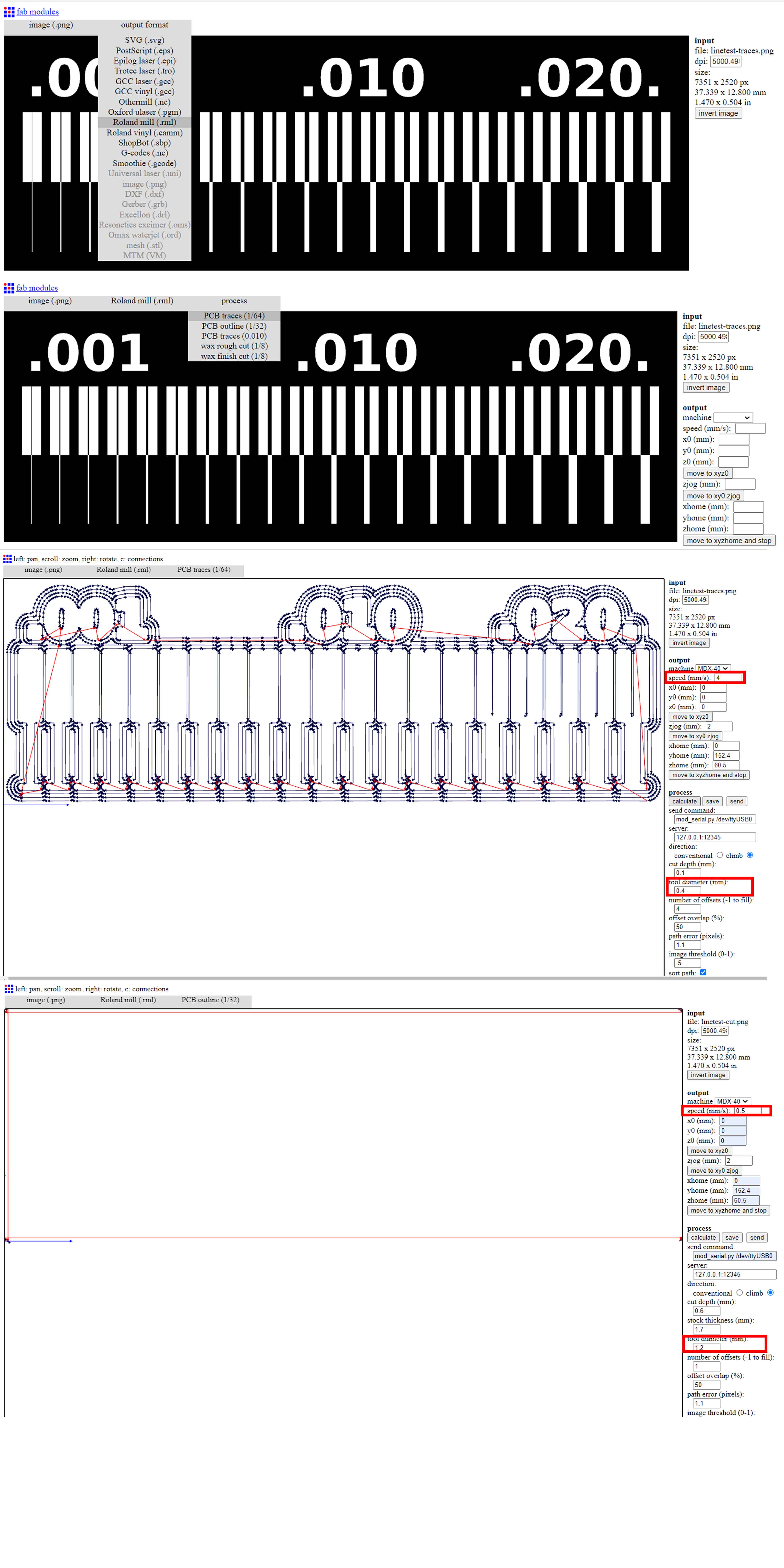
note that these settings are for the internal traces, and we will be using a 0.4mm milling bit
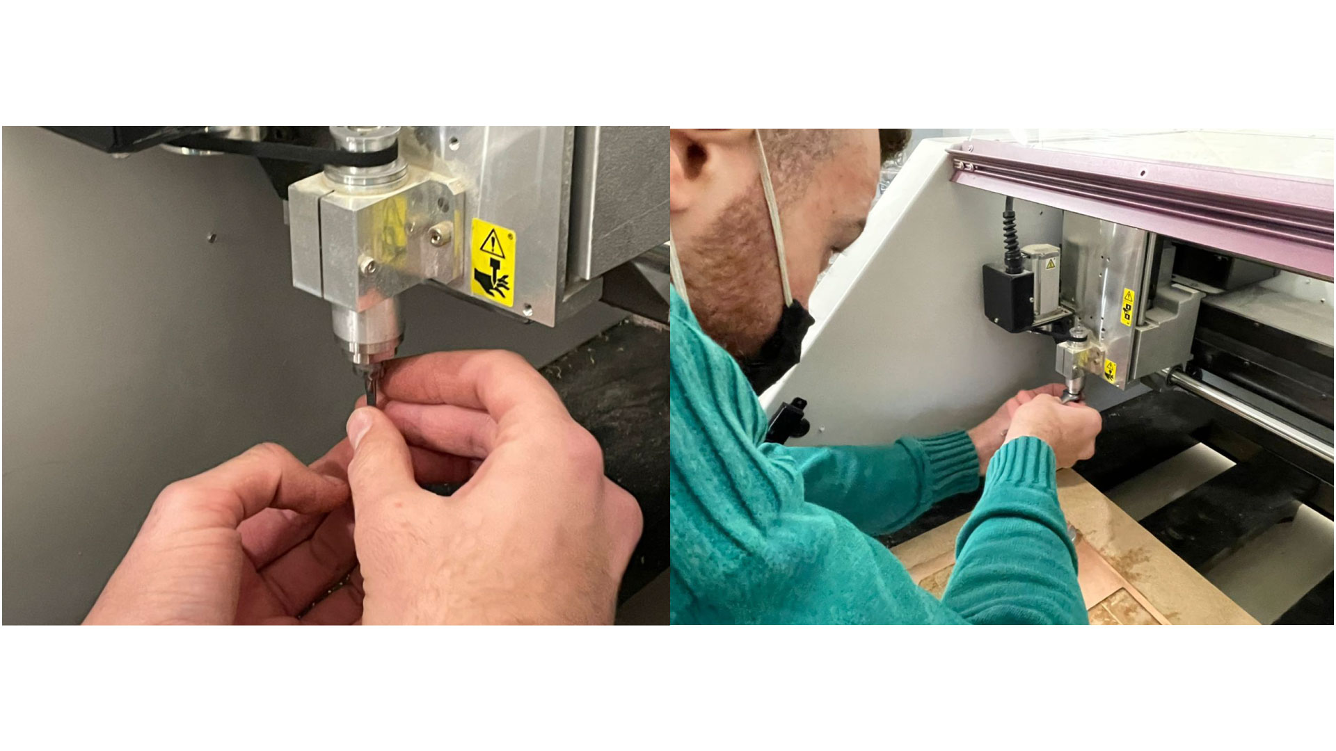
Now that we have our files ready, it is time to go to the machine, turn ON the machine by pressing “power” button and wait for it to initialize, then press “view” to move the machine to the initial origin. Grab the 0.4mm bit that we will use for traces, Insert the router bit into the collet. Retract the router bit by 4 mm or so, and then hand-tighten the collet nut to hold the bit in place. Fully tighten the collet nut with the appropriate wrench
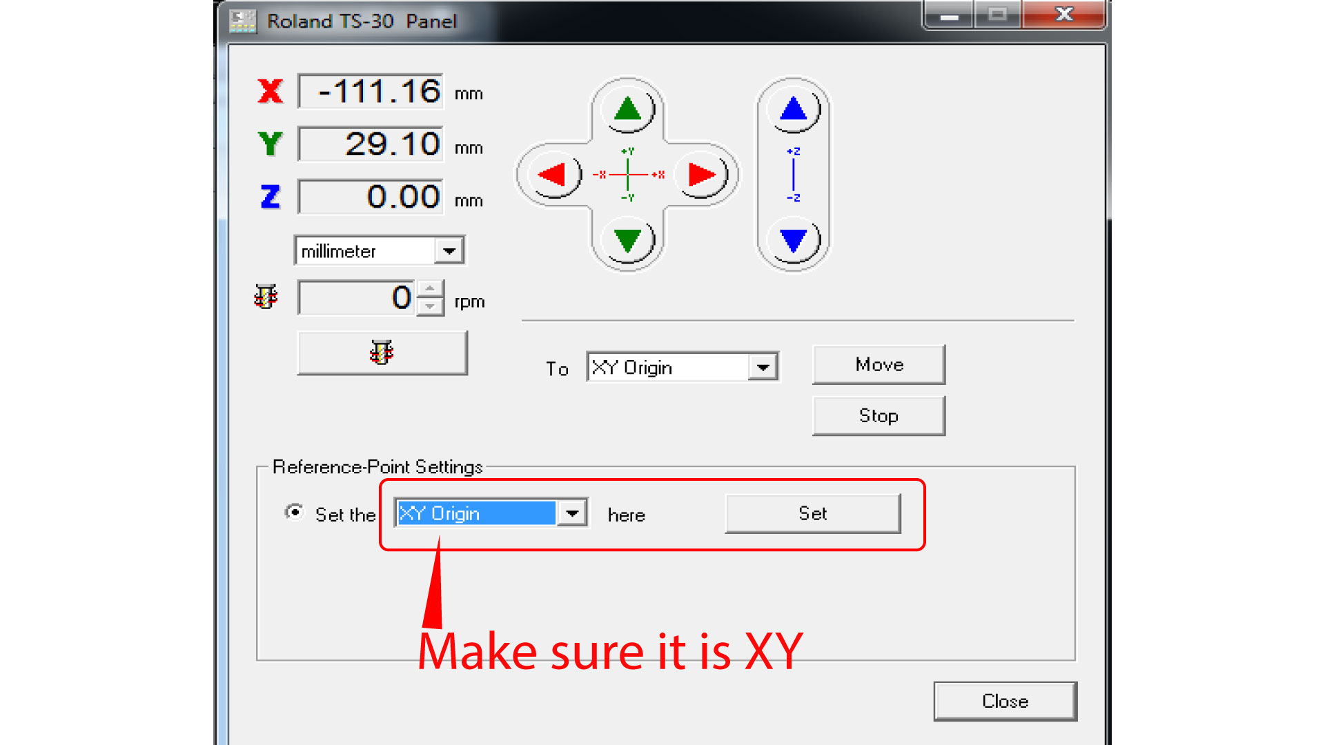
Now go to the PC, open the software “DropOut”, at this stage we want to first zero our XY axis from the software, and Z axis from the machines control panel. Go to “File > Print set up > Properties > Options > Operation panel”. Before moving the XYZ, press “view” on the machine to get it out of the “view” position, now in the operation panel, move the XY axis into your desired starting point, note that the starting point in the generated G-code is bottom-left corner. Then press set XY origin.
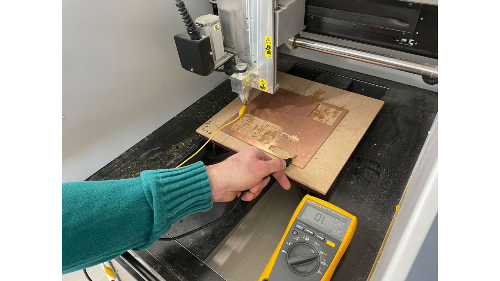
Now we want to zero the Z-axis, to do that, we need a digital multimeter, and an alligator. Put the digital multimeter in buzzer mode and touch the negative and positive ends together to see if it is buzzing, then attach the alligator to one terminal of the multimeter, attach the other end of the alligator to the router bit. Now we want to lower the our Z until it touches the copper board, do not forget to touch the free side of the multimeter with the copper board so when the bit touches the copper the multimeter would beep. Press the down arrow on the machine until it gets close to the board “be careful not to go down too much and break the bit”, then go slowly until the multimeter buzzes, when it does, press the down arrow three little pushes to make sure we have our Z-axis ready.
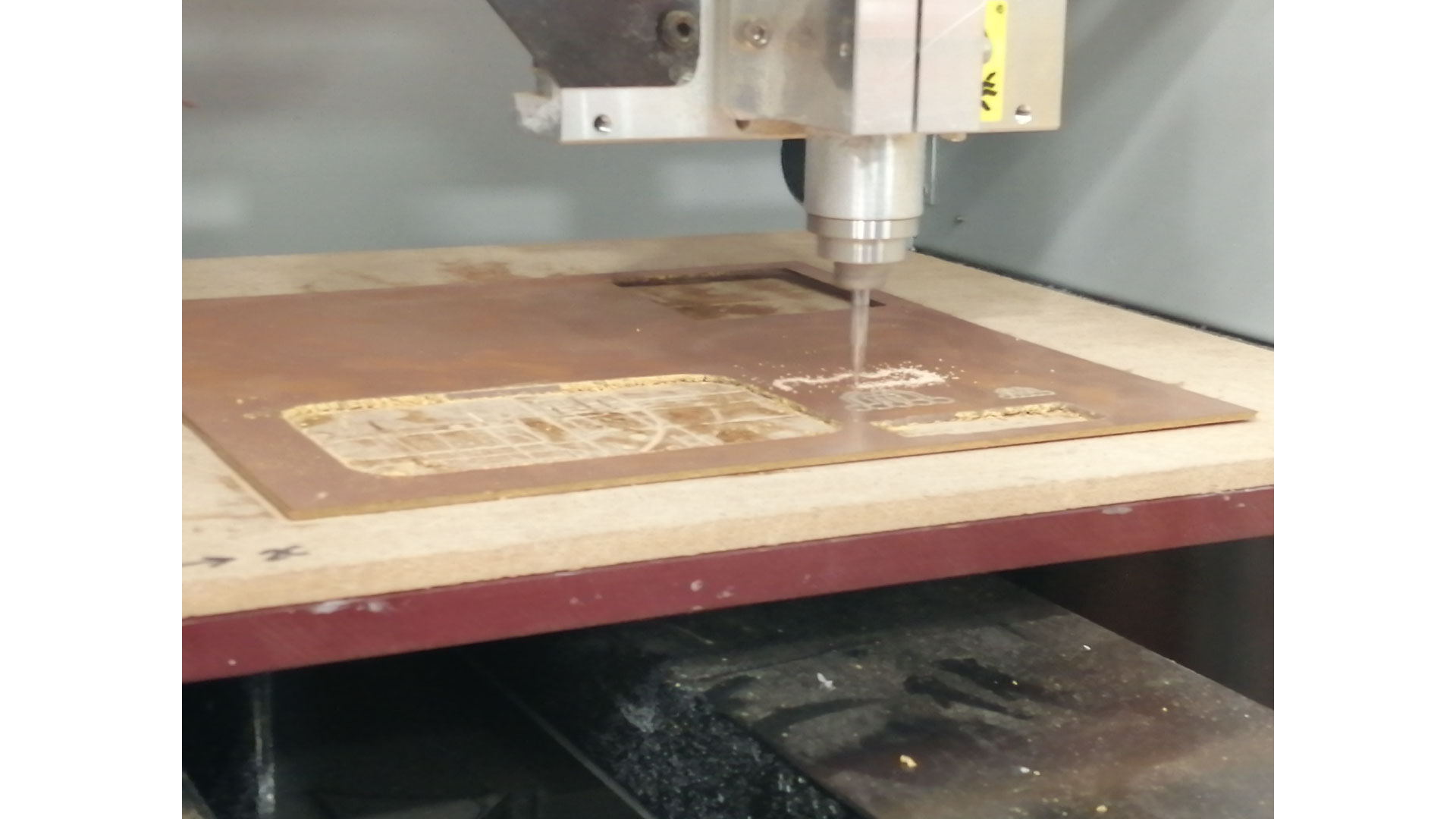
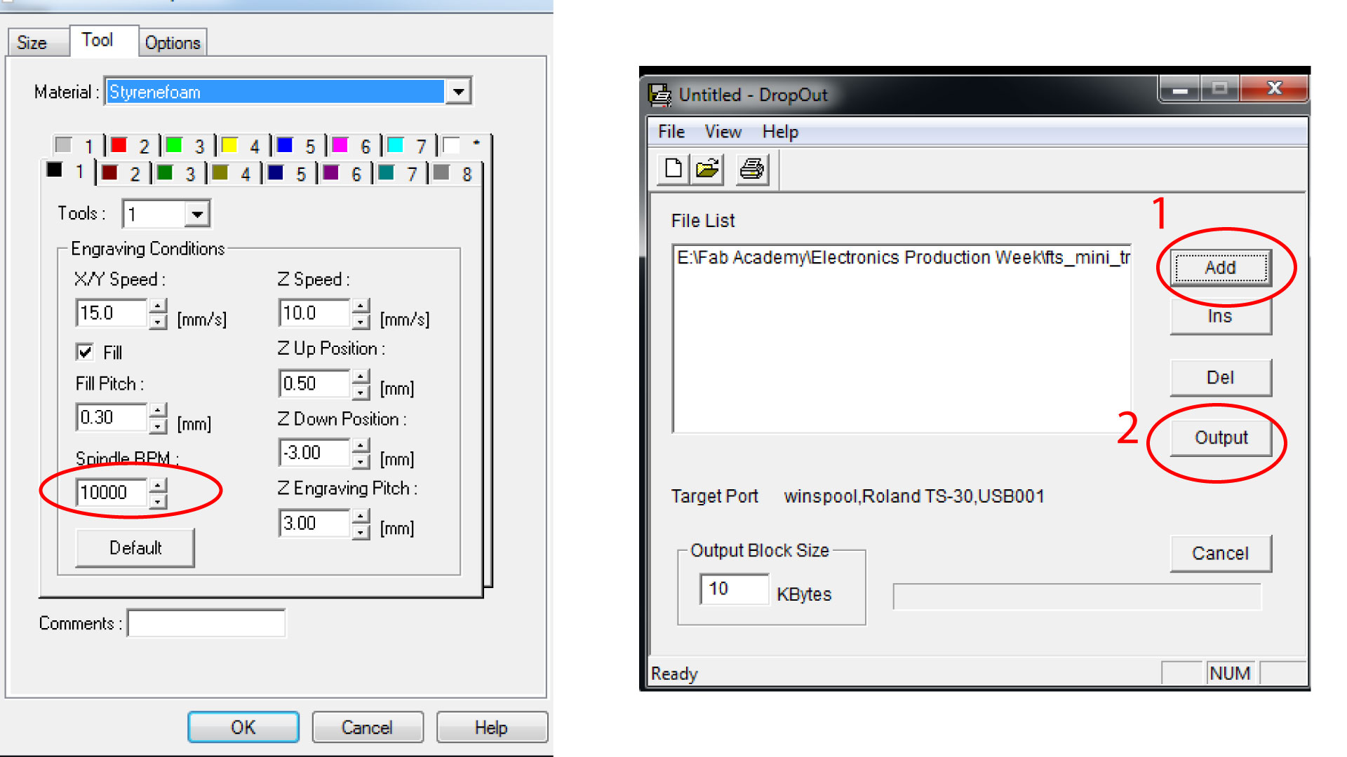
Now, we go back to the software, and in the properties we go to tools, and we select the spindle RPM as 10,000. Then we go to the first window in the software, and we add our traces G-code that we generated previously. Now that we are ready to start the job, press “Output” on the software, the machine should start milling now, do not open the door of the machine unless there is an emergency. When the job is done, wait a minute for the machine to stop, then hit “view”, when the XY goes to the corner, open the door, and use the vacuum cleaner to clear the dust.
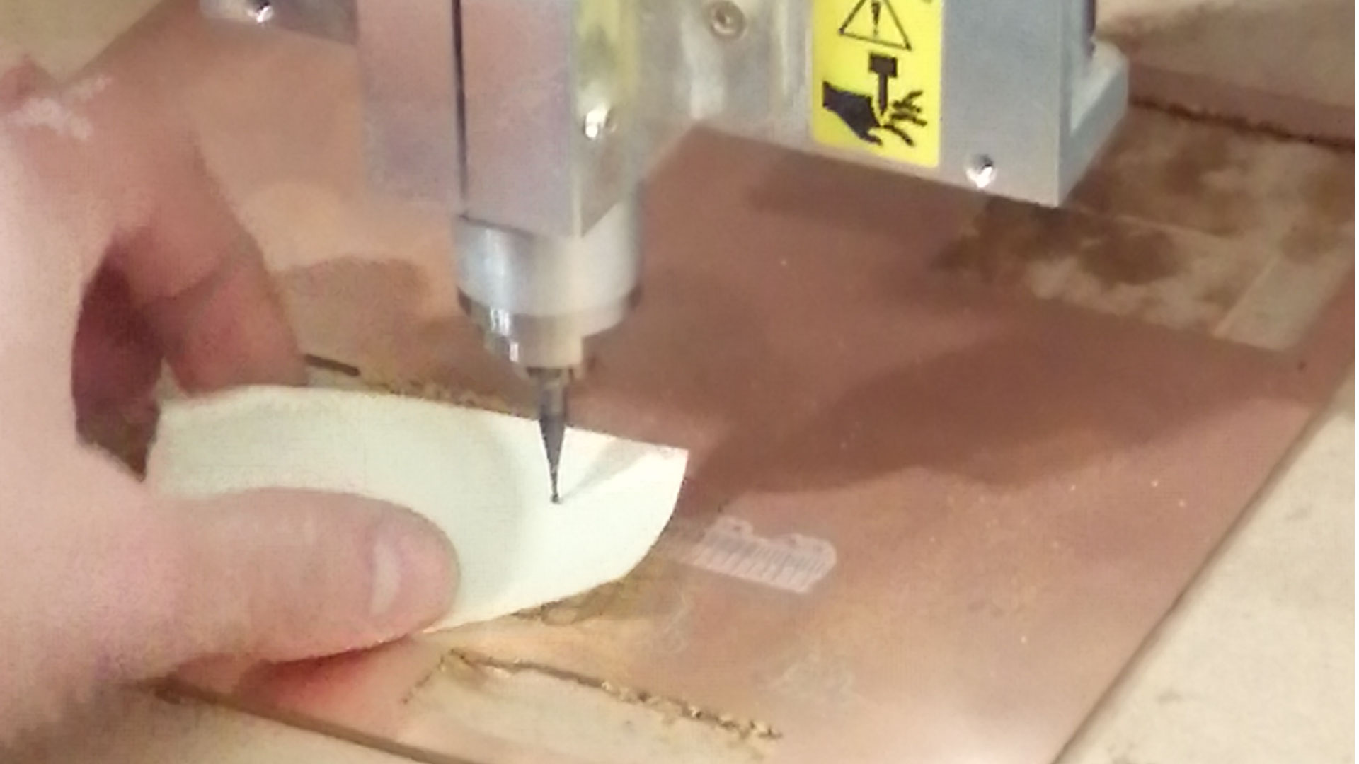
Now we want to cut our outline, to do so, we need to change the bit following the same previous steps, just make sure the bit does not fall down when removing it. we used a 1.2mm bit to cut our outline. After putting the new bit, we need to zero the Z-axis again, we will not use the multimeter this time. Place a paper on the copper board, and carefully move down until the bit touches the paper and makes it hard to move sideways.
Charactarizing the laser cutter
Now that we have our new Z position, we will go to the software, delete the old G-code, and add the outline G-code, then press “Output”, the job should now start. When the job is over, clean the dust, then carefully remove the PCB with by pinching it from the side with a screwdriver. Then, remove the double sided tape that is on the back of the PCB
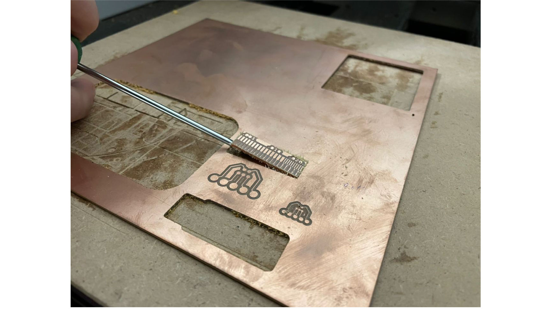
Test Results:
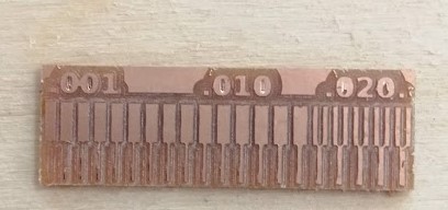
we noticed that not all paths stayed, and the thin paths (less than 0.381mm) were missing. Thus we deduced that we cannot do traces less than 0.381 mm with our bit.
Individual assignment
To build our own In-system programmer, we need to do the following:
-Prepare the design
-Extract the PCB layout image
-Create the G-code
-Mill the copper board to produce the pcb
-Weld the components
-Program the Microcontroller
Preparing the design:
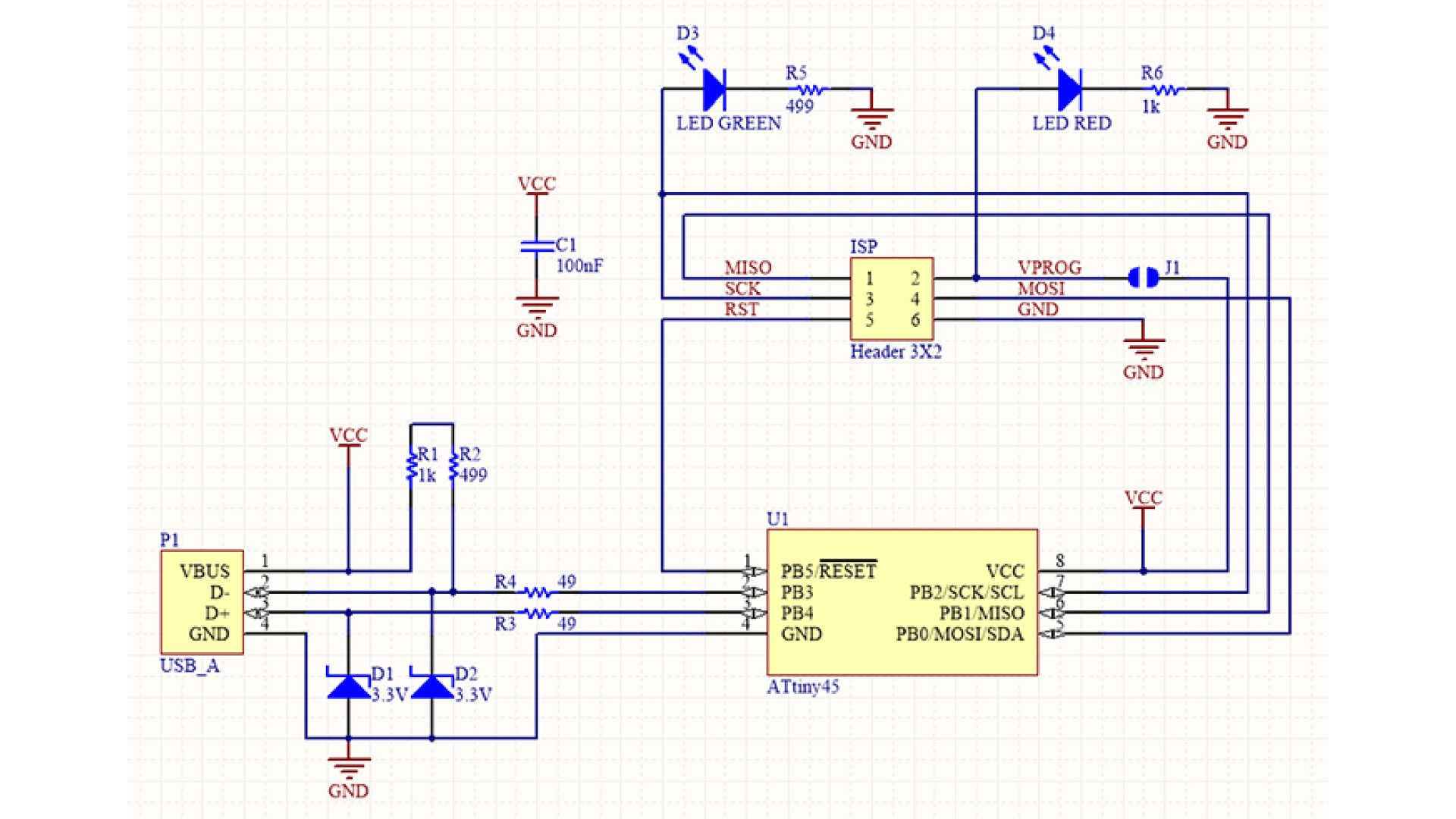
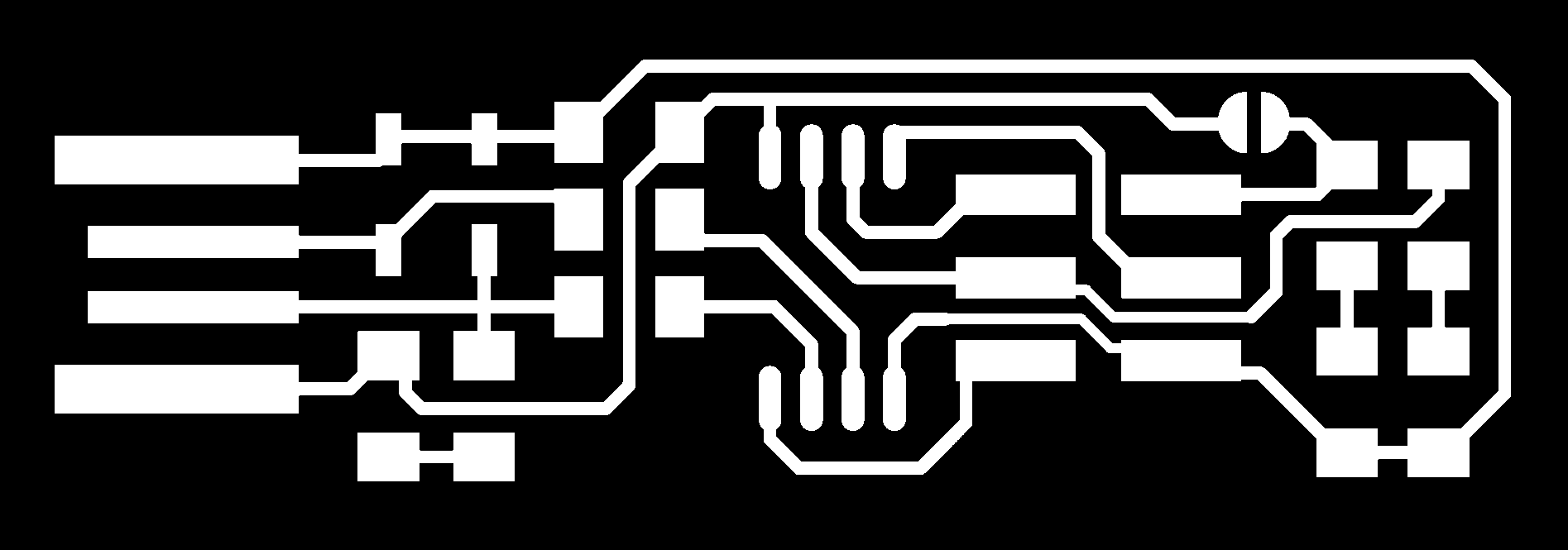
there are different ISP designs to choose from , I have decided to go with the BRIAN pcb. we can use the software eagle to create schematic diagrams of the pcb layout.
Extracting the PCB layout image:
The image should be extracted from Eagle in a Monochrome setting, and opened in illustrator or any other photo editing software (that will not make the picture pixelated or scaled), and we produce to images, one for internal traces, one for external outline.
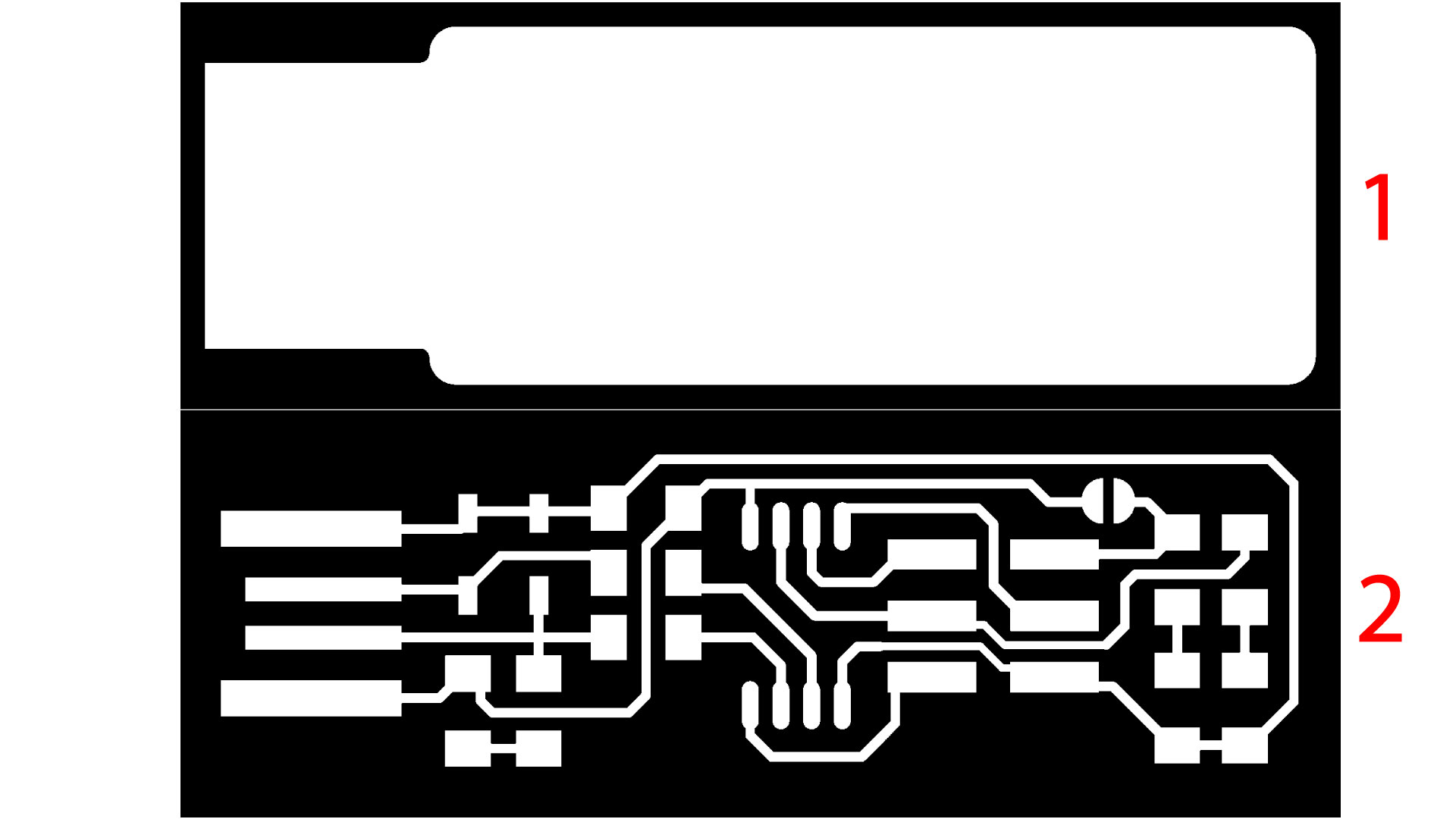
These traces can be downloaded from these links: internal traces, Outlines.
CREATING THE G-CODE:
Following the same steps we used to do the test previously, open fabmodules and do the following:
Choose input format and select image (png)
Then go on to Output format, and if you have the same machine we have, choos Roland mill (.rml)
Then select Process and choose PCB traces (1/64) for internal paths, and PCB Outline (1/32) for the outline cutting.
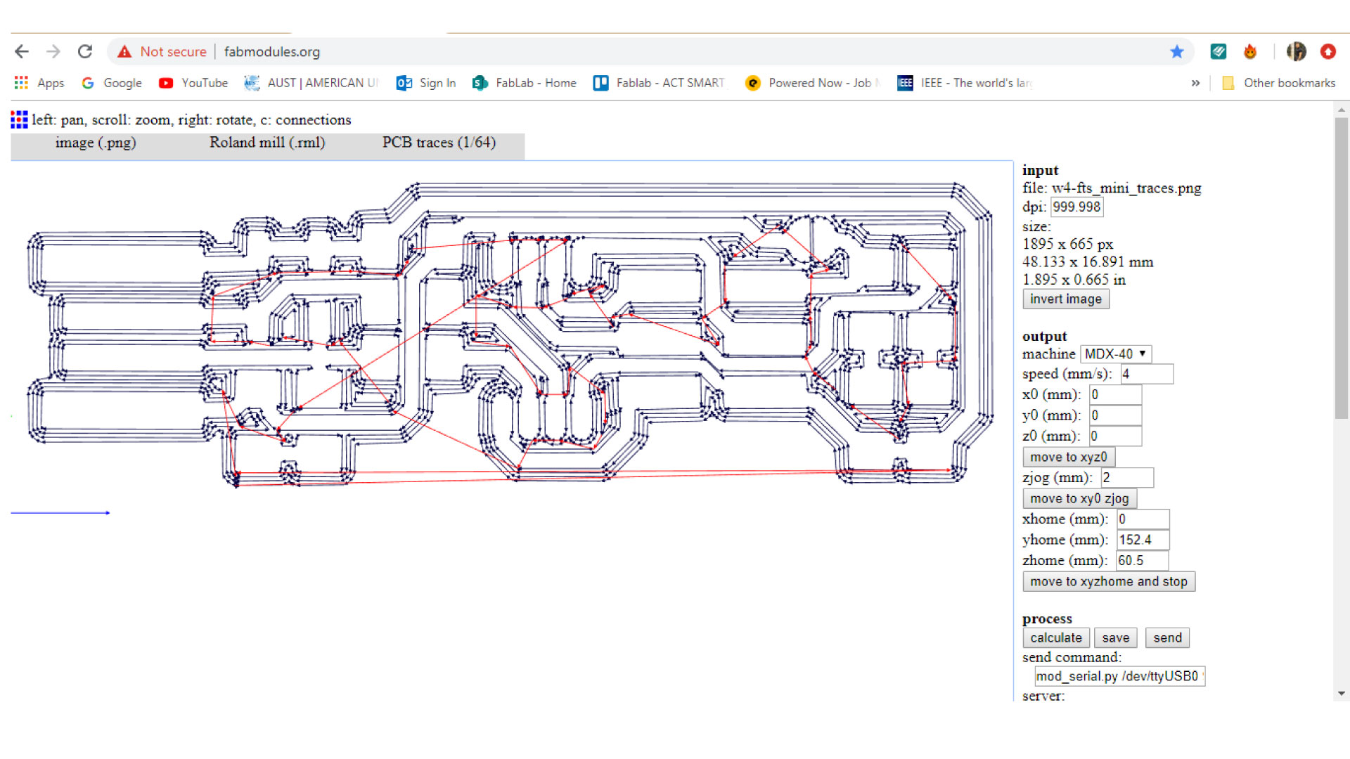
Then, select the CNC machine you are using, in our case Roland MDX-40
Settings for traces:
Speed = 4
X, Y, Z = 0
Cut depth = 0.1 (since we only want to remove the surface)
Tool diameter = 0.4 (we use a 0.4mm bit for traces)
Offset = 4
then we save, and press calculate:
Settings for outline:
Speed = 0.5 (the speed should be lower)
X, Y, Z = 0
Cut depth = 1.7 (Thickness of copper board)
Tool diameter = 1.2 (we use a 1.2mm bit for cutting)
Offset = 1
At last, press the Calculate button. Then finally click the Save button and save it to the designated folder. It would be saved as an .rml file
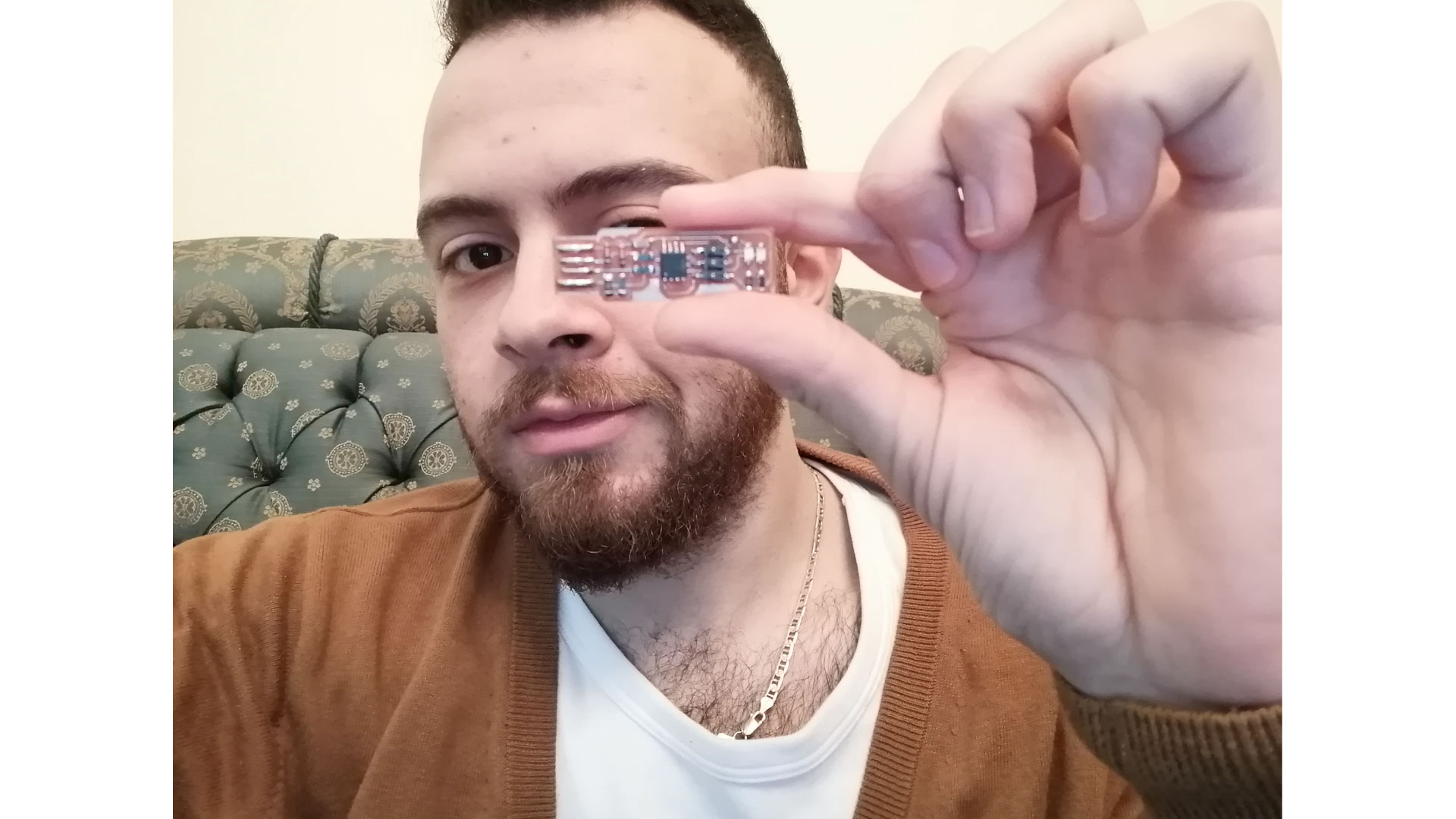
Milling the PCB board:
Open the software “DropOut”, at this stage we want to first zero our XY axis from the software, and Z axis from the machines control panel. Go to “File > Print set up > Properties > Options > Operation panel”. Before moving the XYZ, press “view” on the machine to get it out of the “view” position, now in the operation panel, move the XY axis into your desired starting point, note that the starting point in the generated G-code is bottom-left corner. Then press set XY origin.
Now we want to zero the Z-axis, to do that, we need a digital multimeter, and an alligator. Put the digital multimeter in buzzer mode and touch the negative and positive ends together to see if it is buzzing, then attach the alligator to one terminal of the multimeter, attach the other end of the alligator to the router bit. Now we want to lower the our Z until it touches the copper board, do not forget to touch the free side of the multimeter with the copper board so when the bit touches the copper the multimeter would beep. Press the down arrow on the machine until it gets close to the board “be careful not to go down too much and break the bit”, then go slowly until the multimeter buzzes, when it does, press the down arrow three little pushes to make sure we have our Z-axis ready.
We selected our RPM to be 10000 round per minute, and then added the G-code to the software.
Double check your settings, and then press "output", the machine should now start
SOLDERING THE COMPONENTS
The components used are:
1x ATtiny45 or ATtiny85
2x 1kΩ resistors
2x 499Ω resistors
2x 49Ω resistors
2x 3.3v zener diodes
1x red LED
1x green LED
1x 100nF capacitor
1x 2x3 pin header
The ATtiny85 comes with 8KB of programmable memory, as for the ATtiny45, it comes with 4KB of programmable memory.
The red LED with a resistor is added to light once the programmer is powered, and the green LED with resistor is added to light when the programmer is talking to the target.
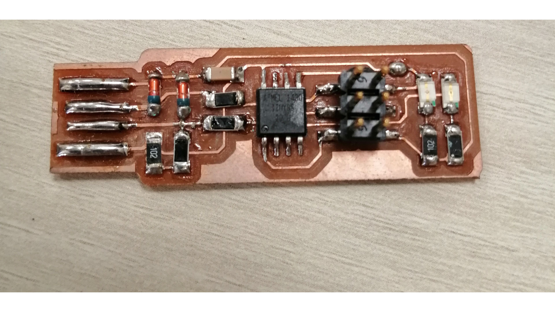
Double check the orientation of the components, the zener diodes are marked with a line on the cathode side, the LED cathodes on the PCB drawing are marked with dots and thicker lines. The ATtiny85 is marked with a small dot on top
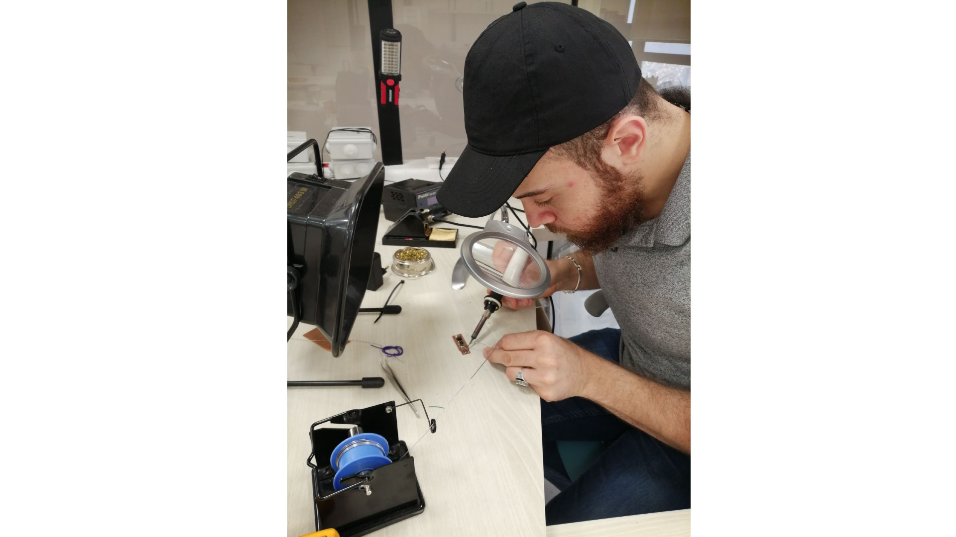
During soldering, check connections with a digital multimeter.
Progrmming The Microcontroller
We will be using ubuntu linux
After finalizing all the required hardware components needed to build the PCB, the next step is to download the Software on the ISP by doing the following:
Open Arduino IDE
Connect Arduinoto the PC
Select the port, and select Arduino UNO in TOOLS
Go to Files > Example > ArduinoISP, and upload it
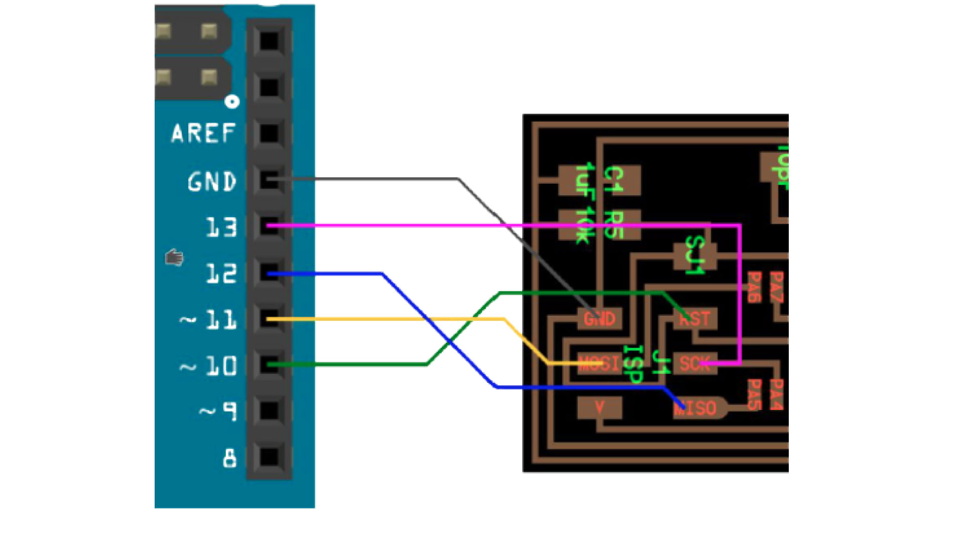
Connect your ISP to the arduino as shown below:
Download the Frimware, and extract the ZIP file.
Open the command prompt in Linux and go to the code directory.
Write the following commands:
make clean
make
Then, replace the make file with this Modified make file.
Open the Make file with Brackets and replace MDU=attiny45 by MDU=attiny85 if you are using the ATtiny85 microchip, and save the file.
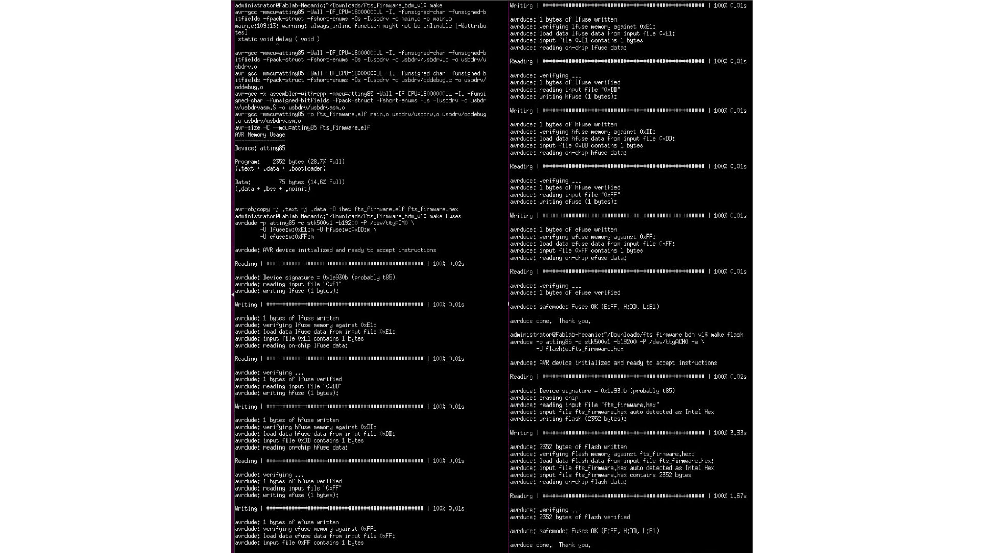
Then, enter the following commands to load the program on the ISP
make fuses
make flash
Now, we want to test if the PC recognizes the ISP, disconnect it from arduino, and connect it to the PC using a USB cable (preferred not connect it directly to PC at this stage)
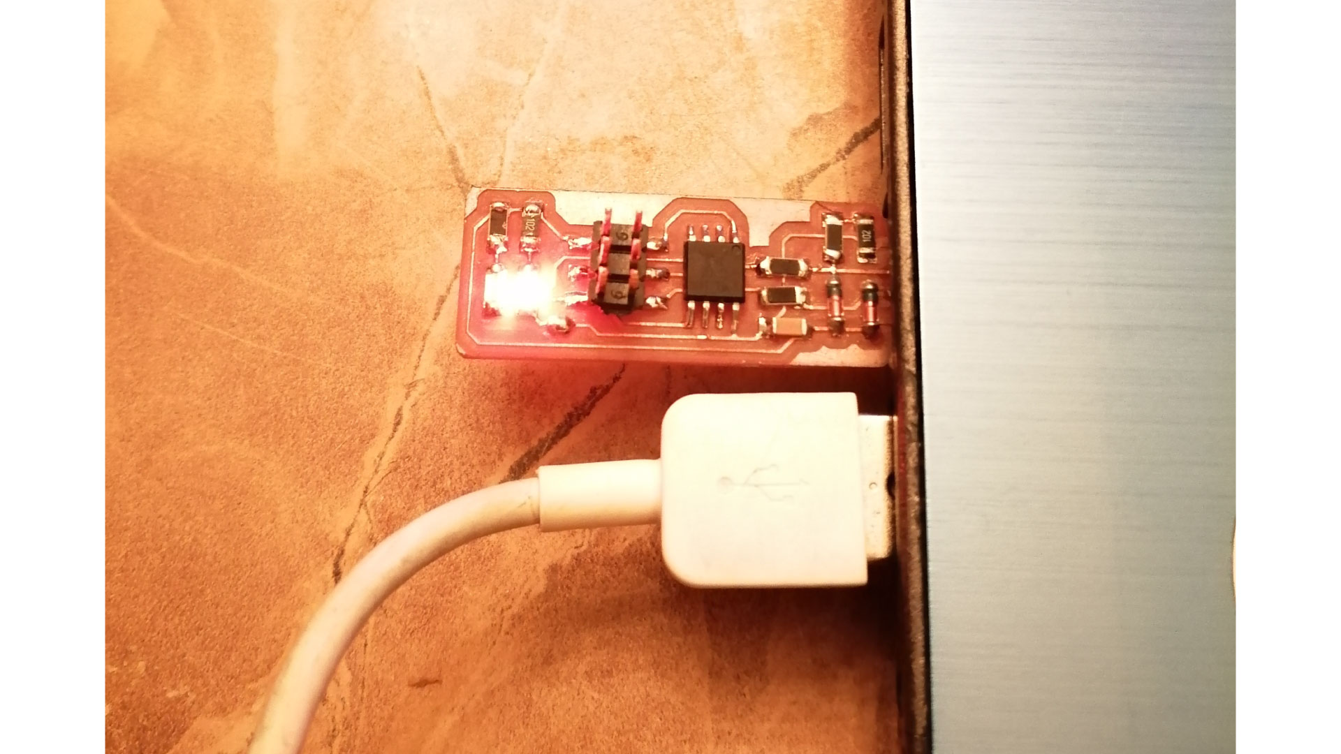
Then, type 'lsusb' in the linux command propmpt and you should see in the list USBtiny, if this is the case, then you have done the steps correctly.
Now that we have tested the ISP, disconnect it from PC and reconnect it to arduino, and type "rstdisbl" in linux, this will set the reset pin to GPIO, and disable the ability to reprogram the microcontroller
