Computer Controlled Cutting - 03
Discovering Computer Controlled Cutting Machines
Objective of week 03
The objective of this week was to discover various computer controled cutting machines, Like the laser cutter, and the vinyl cuter. And we were assigned to do the following:
1- Group assignment: Charactarize the laser cutter we have in the lab, and make test parts that vary in settings
2- Individual assignment: design, lasercut, and document a parametric construction kit which can be assembled in multiple ways
Laser cutting
What is a laser cutter
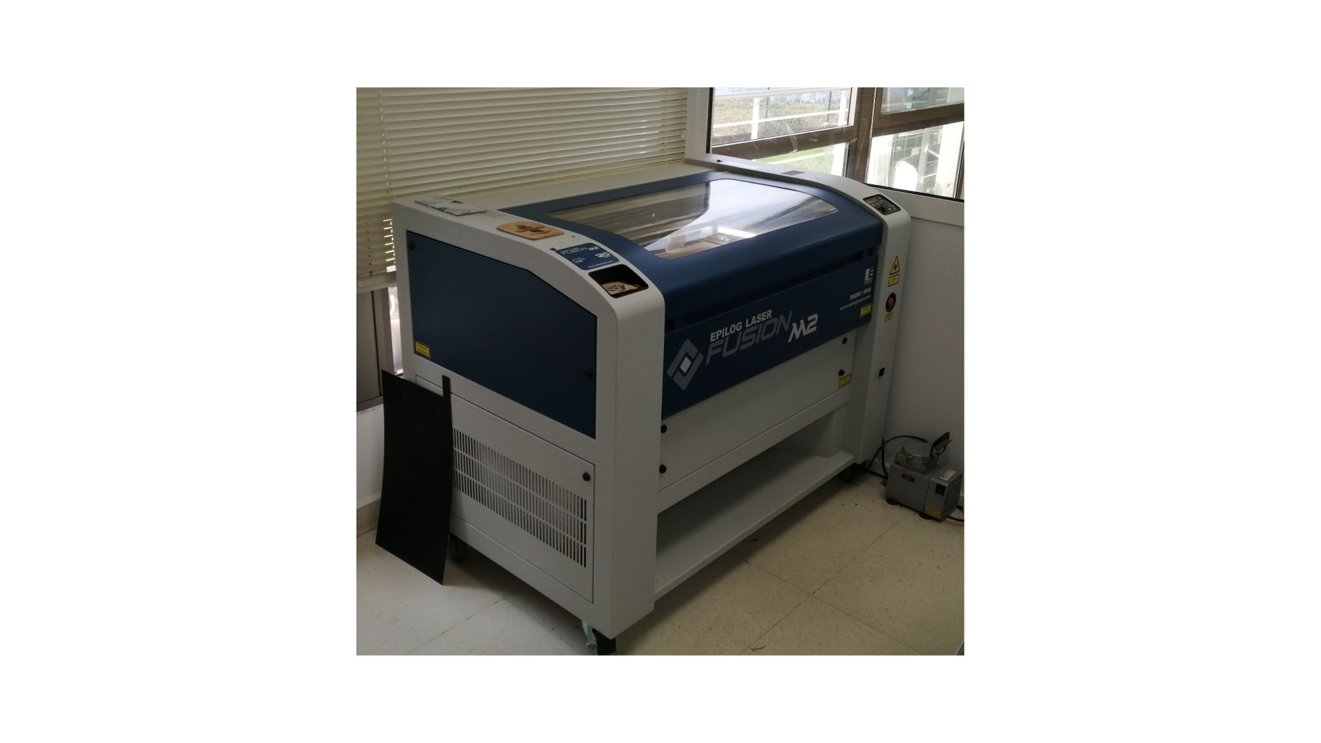
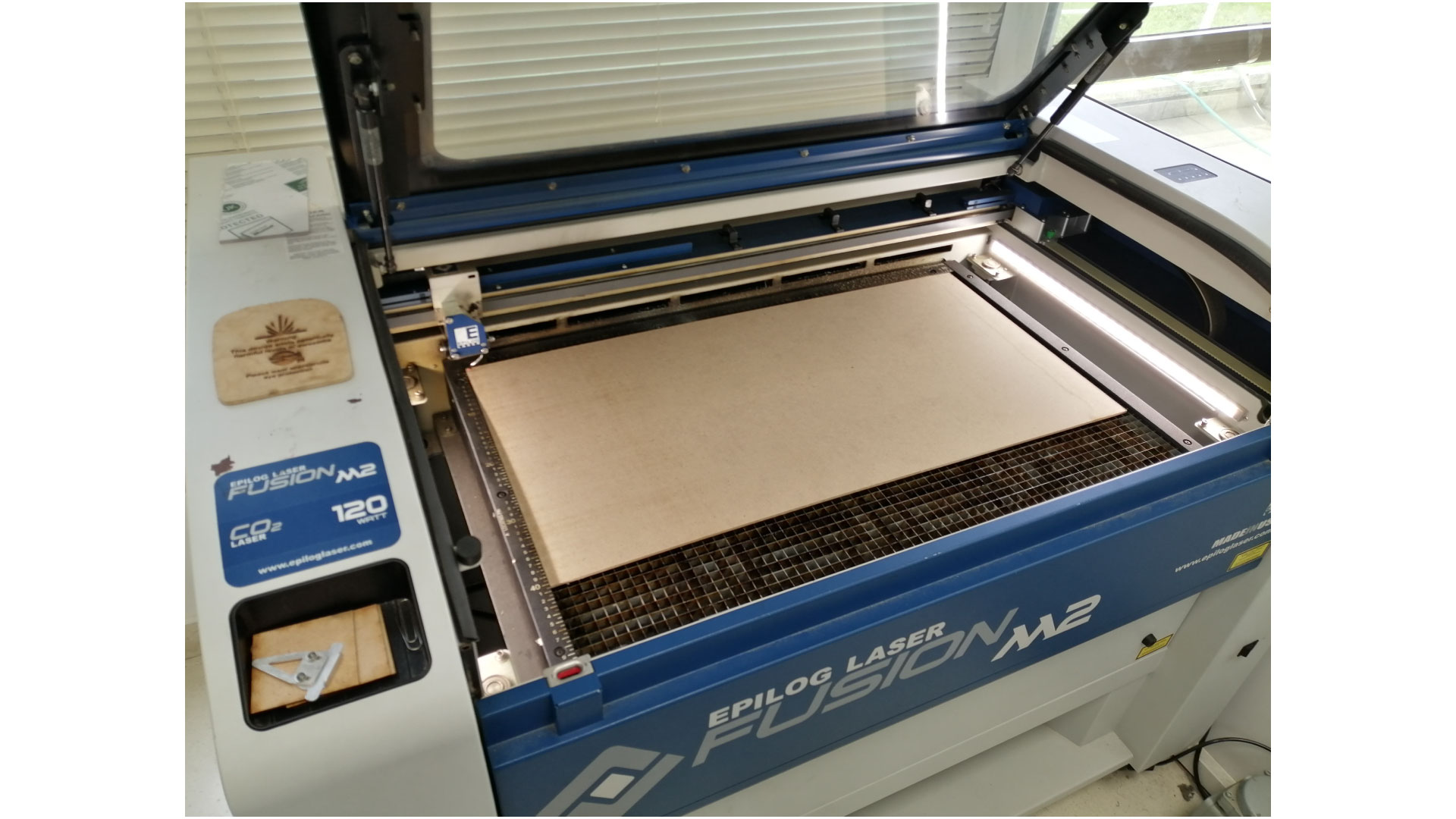
A computer controlled machine that uses a highly focused laser beam to cut or engrave material precisely. In our case, we use the Epilog Fusion M2 120 watts laser cutter. The working area of this laser cutter is 80cm X 50cm, and we can cut and engrave materials like wood (12mm), glass, cork, leather, cardboard, paper, fabrics, non-PVC acrylics, and other organic materials (up to 13mm). It can be used to make prototypes, souvenirs, artistic products, can be used in fashion, toys, home decoration, engraving signs, cutting pieces of models, raster engraving, cutting patterns, etc...
Charactarizing the laser cutter
Working area: 800mm x 500mm
Materials: wood (12mm), glass, cork, leather, cardboard, paper, fabrics, non-PVC acrylics, and other organic materials (up to 13mm)
File format: .DXF, .CDR, .EPS, JPG, and BMP for raster.
Power: 120 Watts
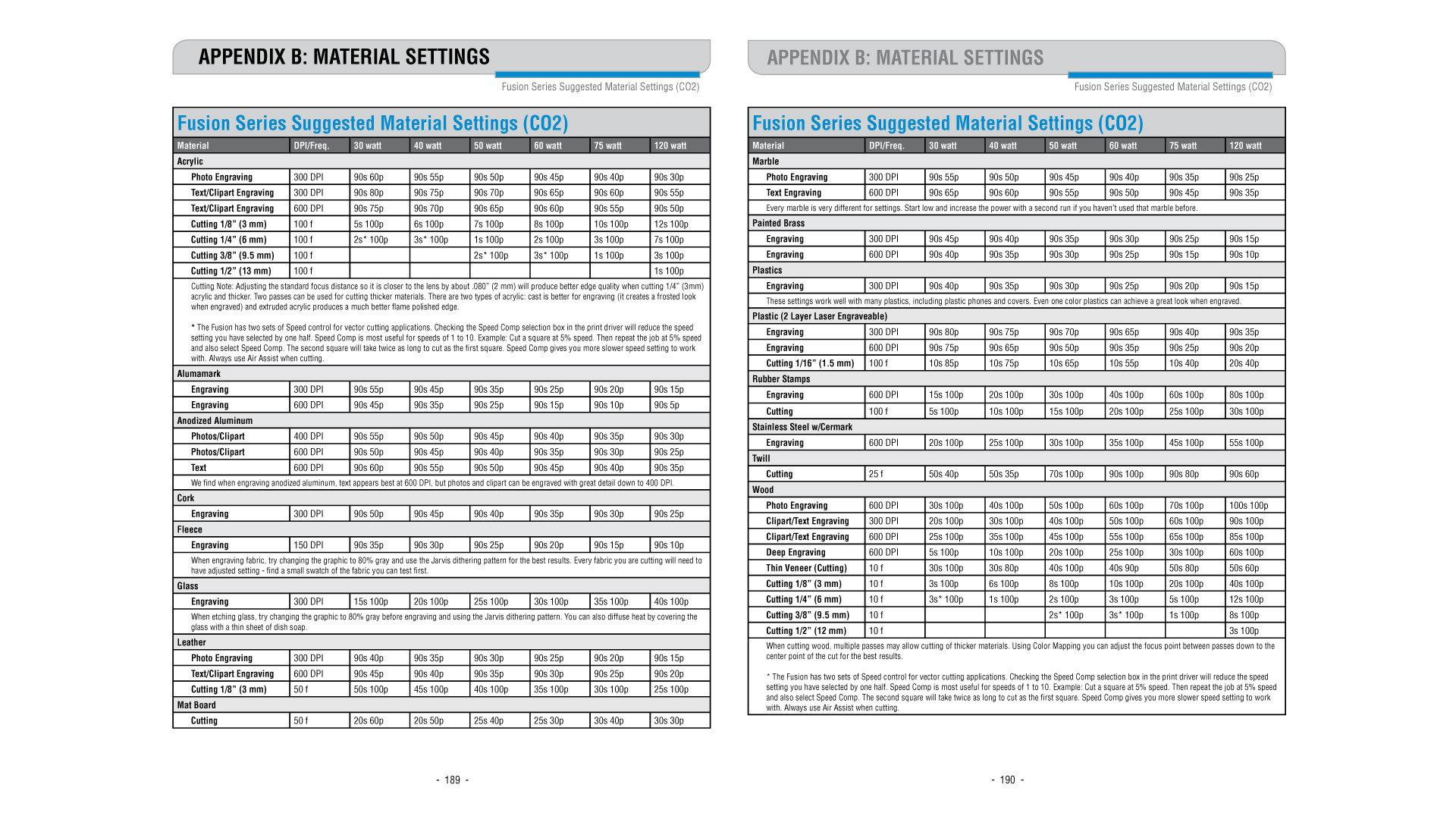
Fusion Series Suggested Material settings for Power, Frequency and Speed:
How to use the laser cutter:
Design
To create a cutting path, the design should be a vector, images cannot be cut. We can use any 2D modeling software to design our vectors, like AutoCAD or illustrator, and we save our design in .DXF 2007 format.
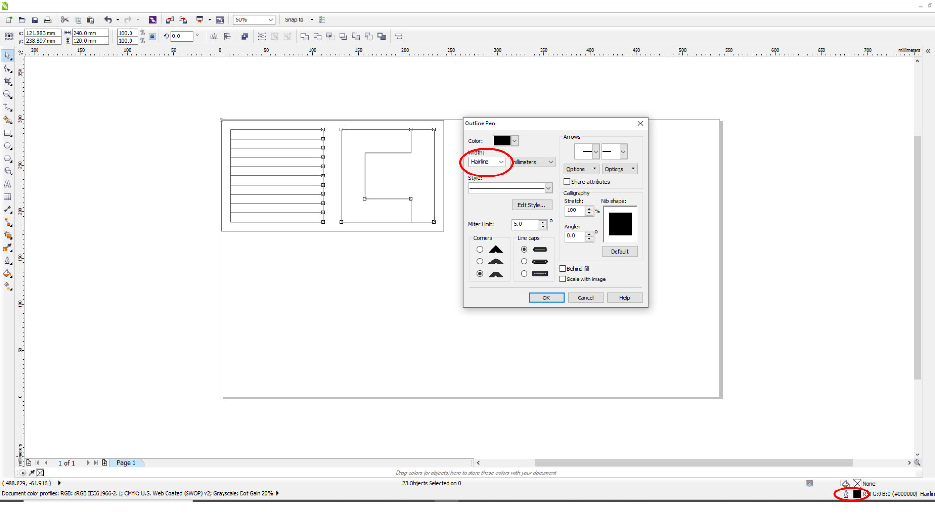
We then open our desigred design in Corel draw to set it up, we must change the media size to 800x500. All the vectors that we want to cut should be changed to "Hair Line".
This is the kerf test desgin placed in corel draw, we want to cut this design on 3.5mm MDf board
If we are satisfied with our design and want to proceed with the job, we have to change the settings. Press Ctrl+P to open the print setup page, press on properties and you will have the Epilog fusion properties window where we can change the power, frequency, and speed settings.
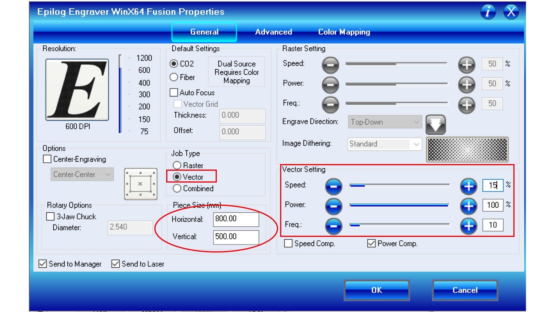
Choose the job type as "Vector", since we only want to cut, Do not forget to change the piece size to match the size of the board you are cutting on. As for the vector settings for cutting MDF, Power must be 100, and frequency 10 according to the Fusion Series Suggested Material settings, i selected speed as 15% (based on testing for 3.5mm thick MDF). Then we press ok
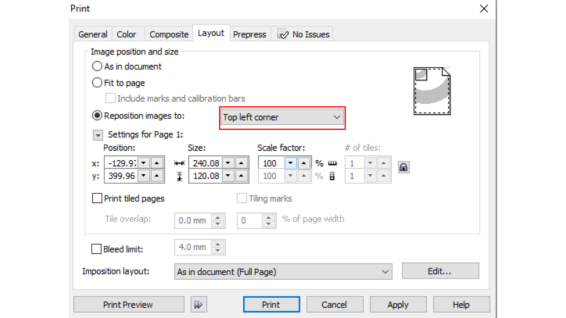
Then, we go to layout, and we choose our starting reference point as "Top left corner"
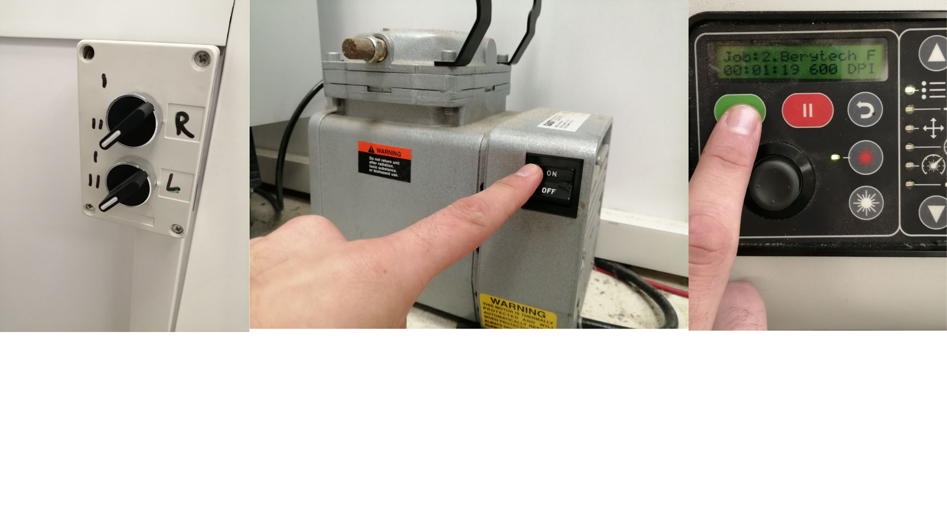
Before pressing "print", we have to get our laser cutter ready. Turn on the laser cutter, and wait for it to initialize, then place your material inside the laser cutter.
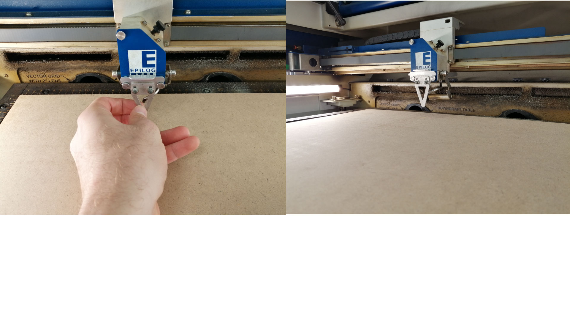
After placing our MDF board, we want to adjust the Z-axis, we place the "V-Gauge" on the carriage, select the focus option from the control panel by pressing on the down arrow, using the joystick, rise the bed until it touches the “V” shaped gauge, then press the joystick to set the Z-axis home position, remove the gauge.
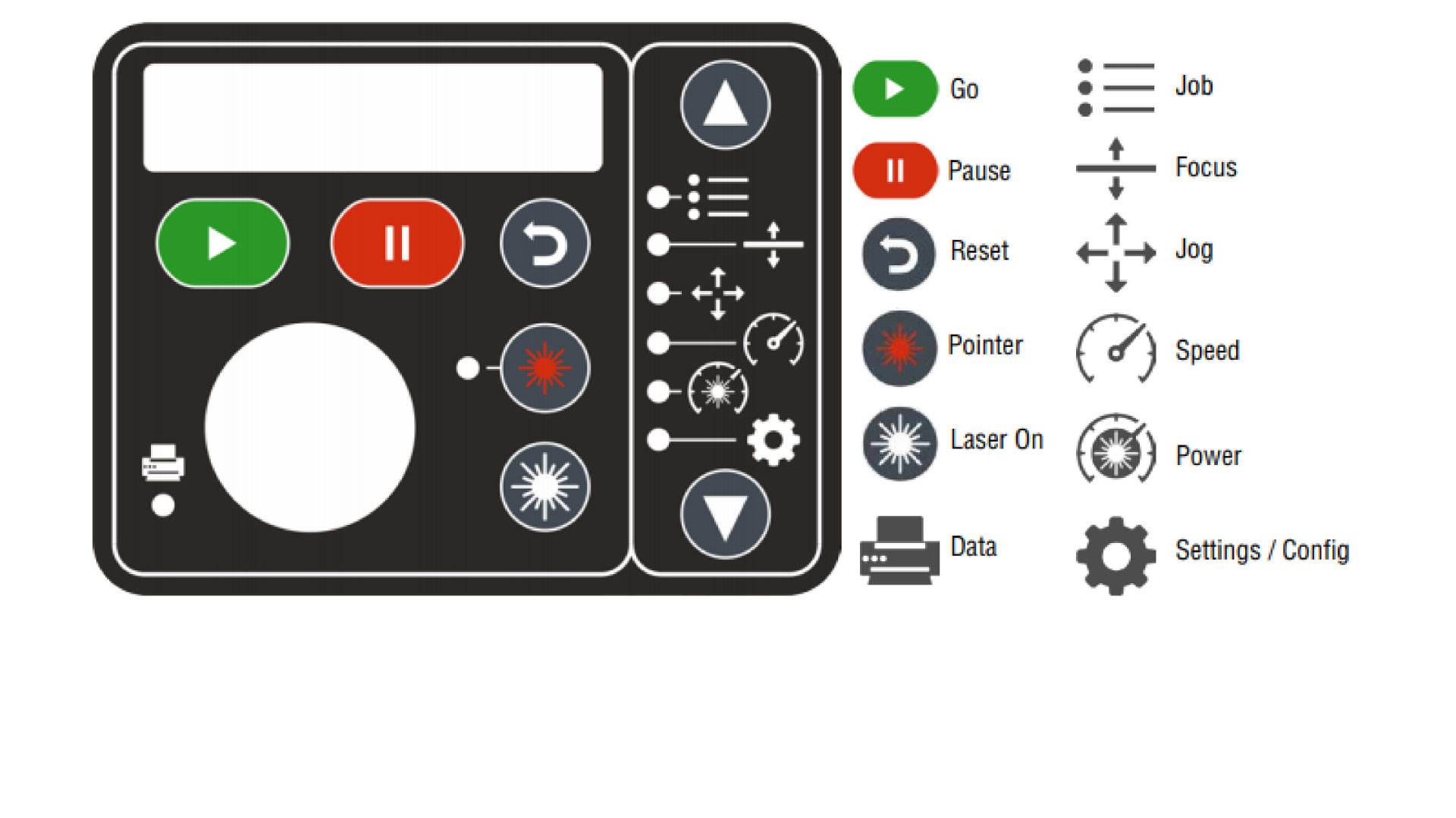
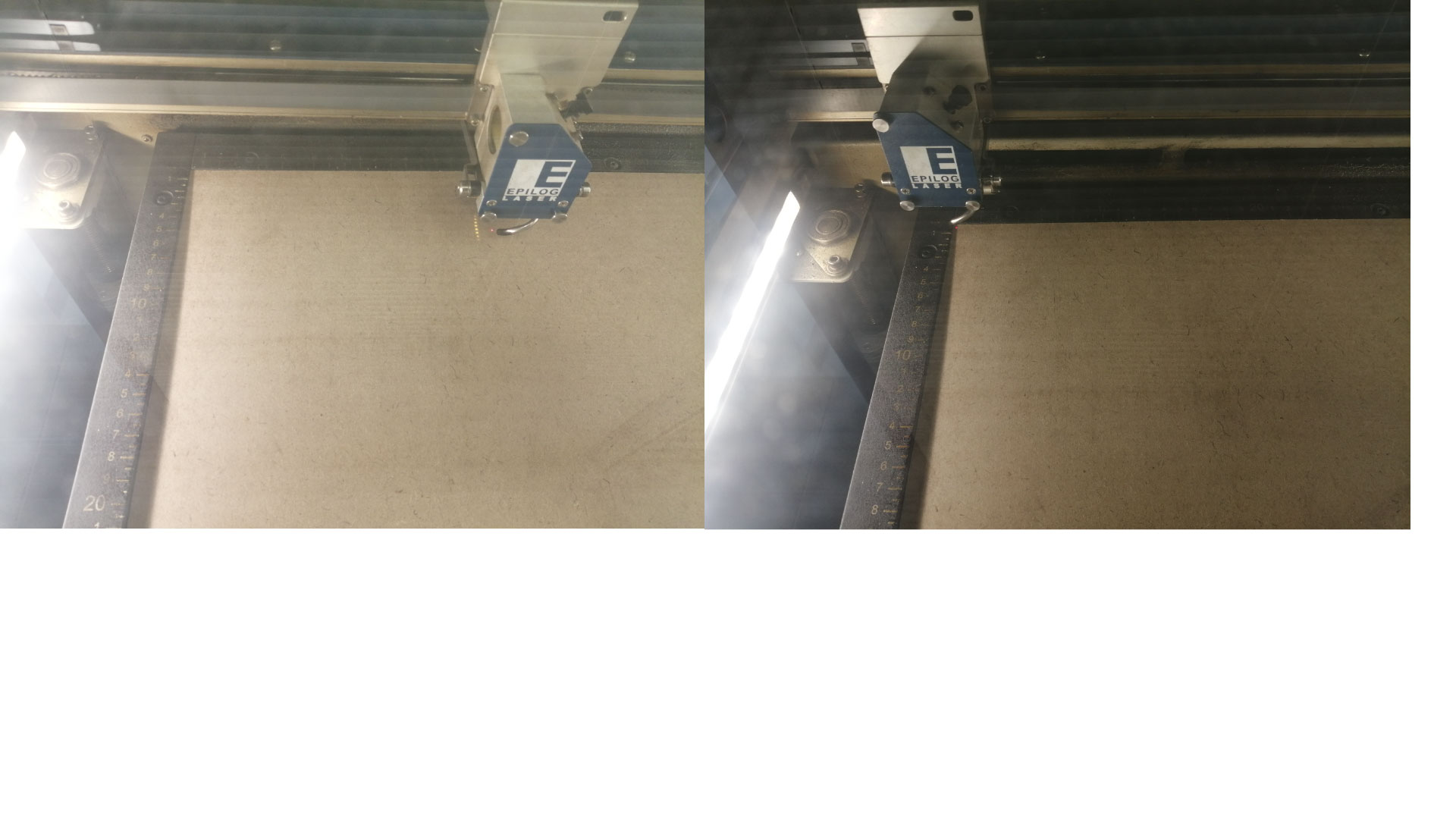
Now that we have the Z-axis initialized, we will have to choose the starting point, select the jog option from the control panel. To make it easier to use, turn on the Red Dot Pointer as a visual indicator, then go to the top left corner using the joystick, and press on the joystick to set the starting point.
Now we are ready to start the laser cuttig job. Press print from the PC, before starting the laser cutter, make sure to turn on the air ventilators and the air compressor, then we press on the play icon on the laser cutter to start the job.
We can see the timing of the laser cutting job on the contorl panel
as the job starts, make sure to stay close to the laser cutter until it finishes
Wait for a minute for all the fumes to be extracted, then open the hood of the laser cutter and remove your items
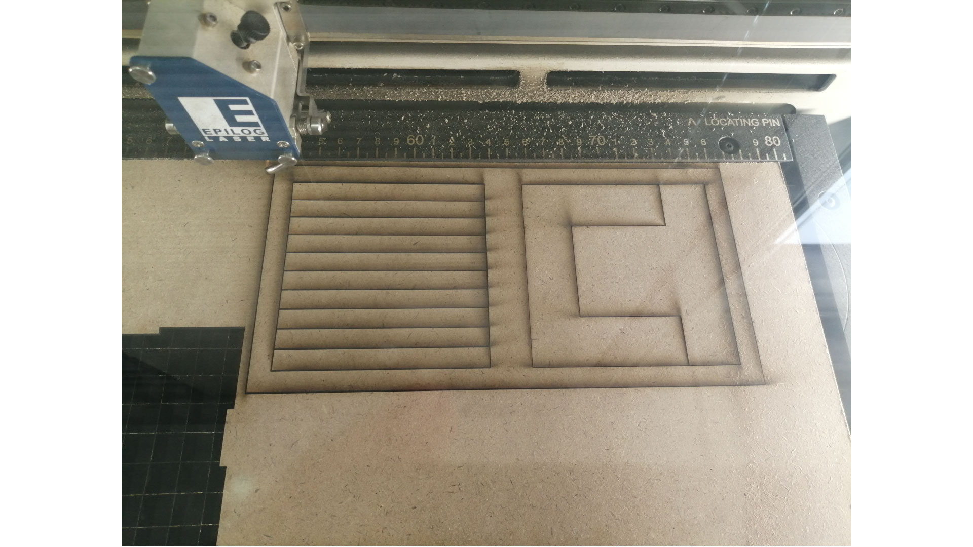
Doing the Kerf test
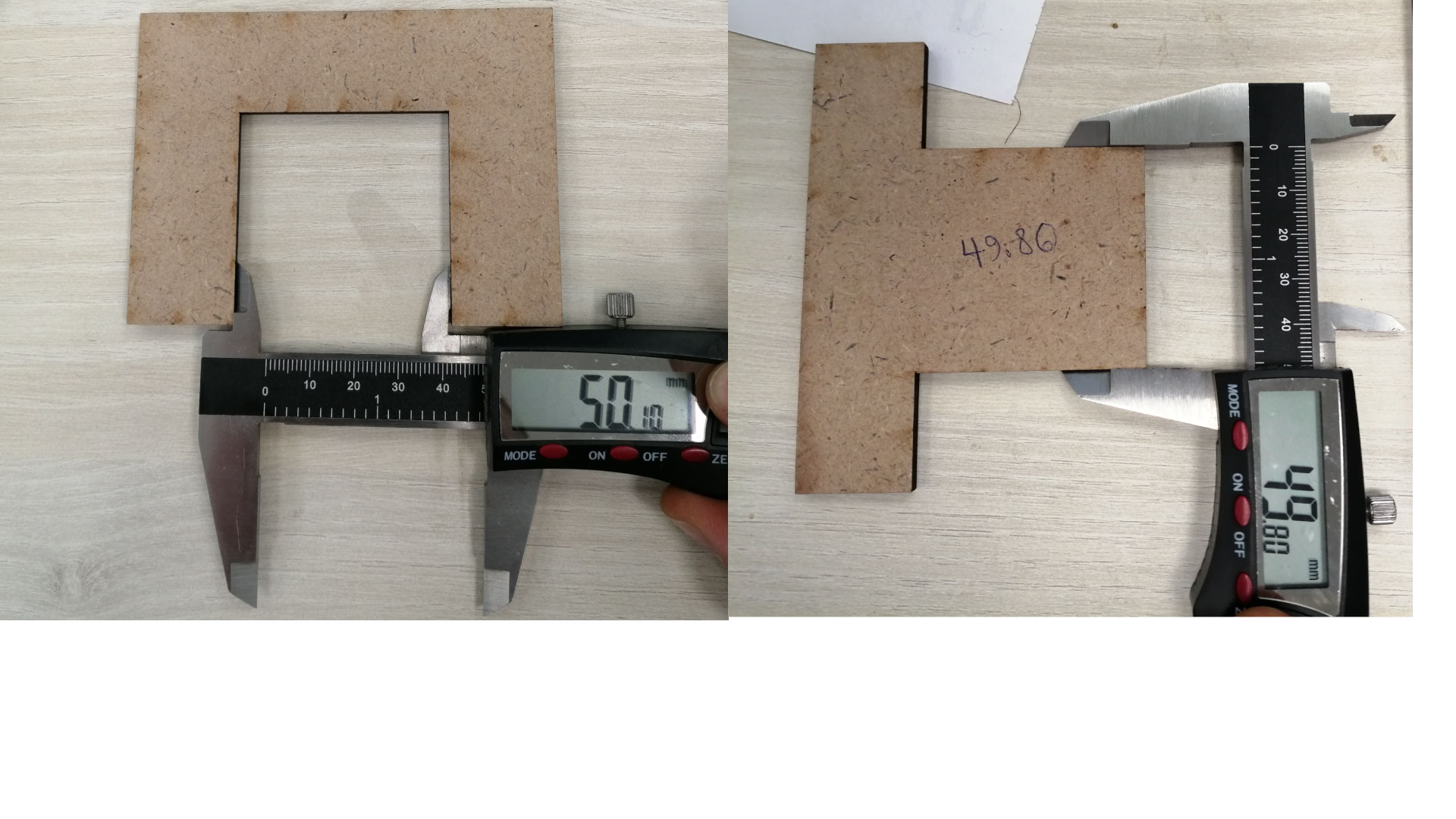
To do the kerf test, we grab our caliper and we measure The Area A and B
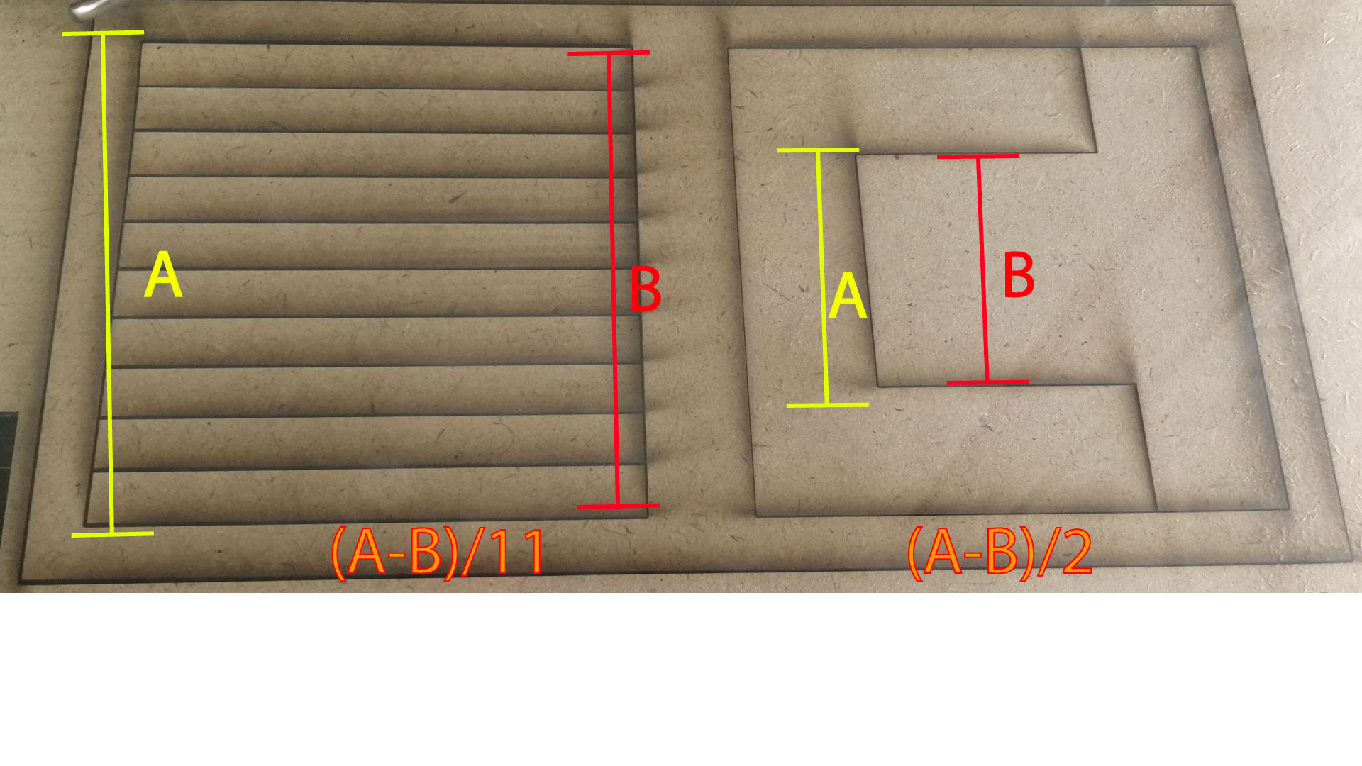
The results of test A:
Test A: (100.3 – 98.65)/11 =0.15
Note: 11 is the number of cuts
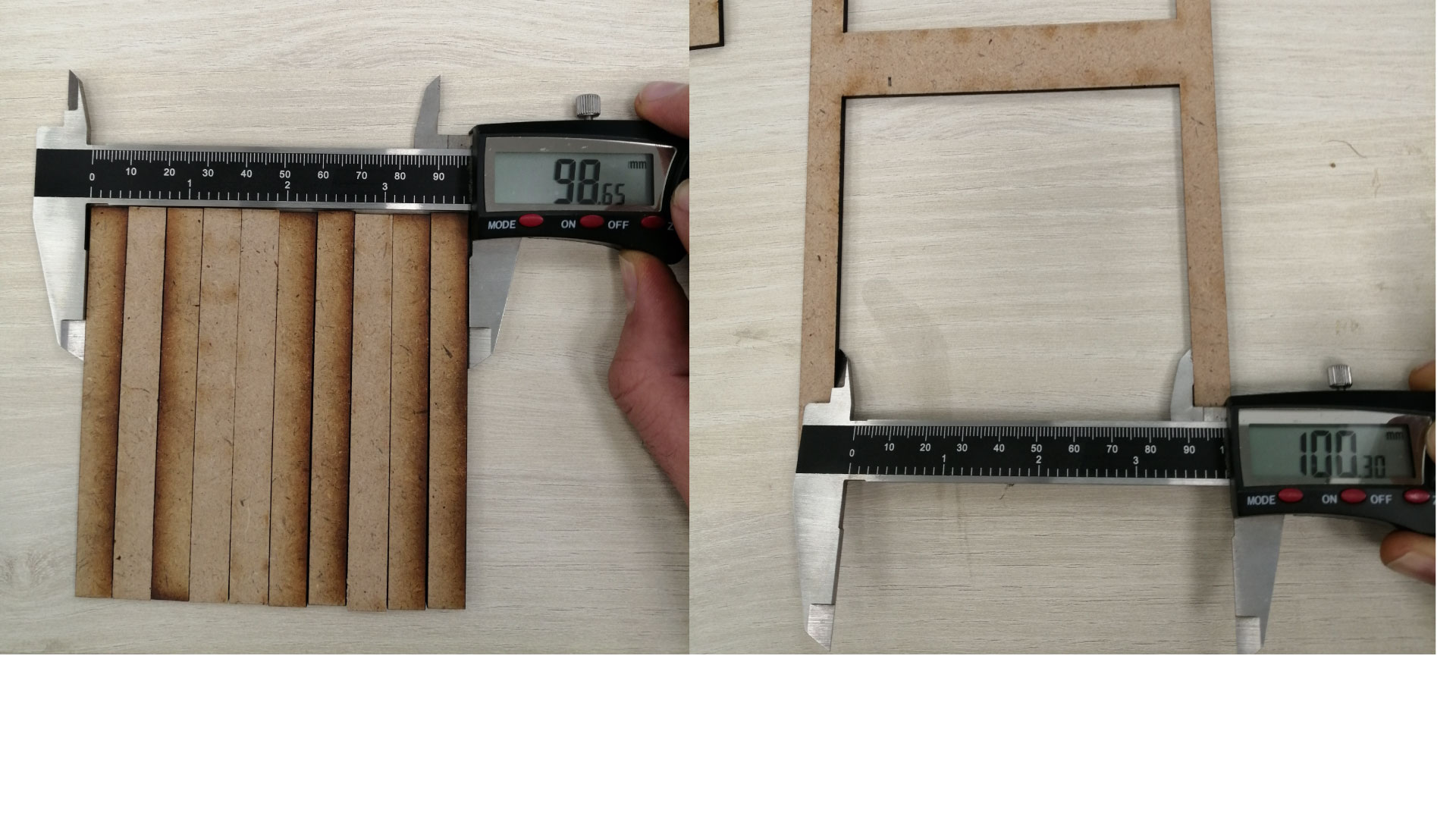
The results of test B:
(50.10-49.80)/2= 0.15
Raster settings
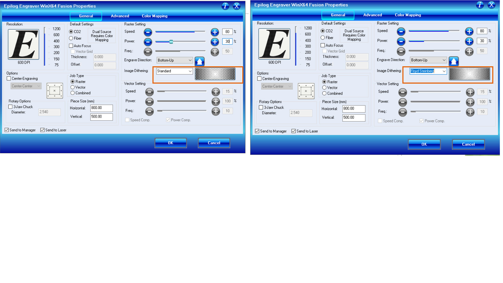
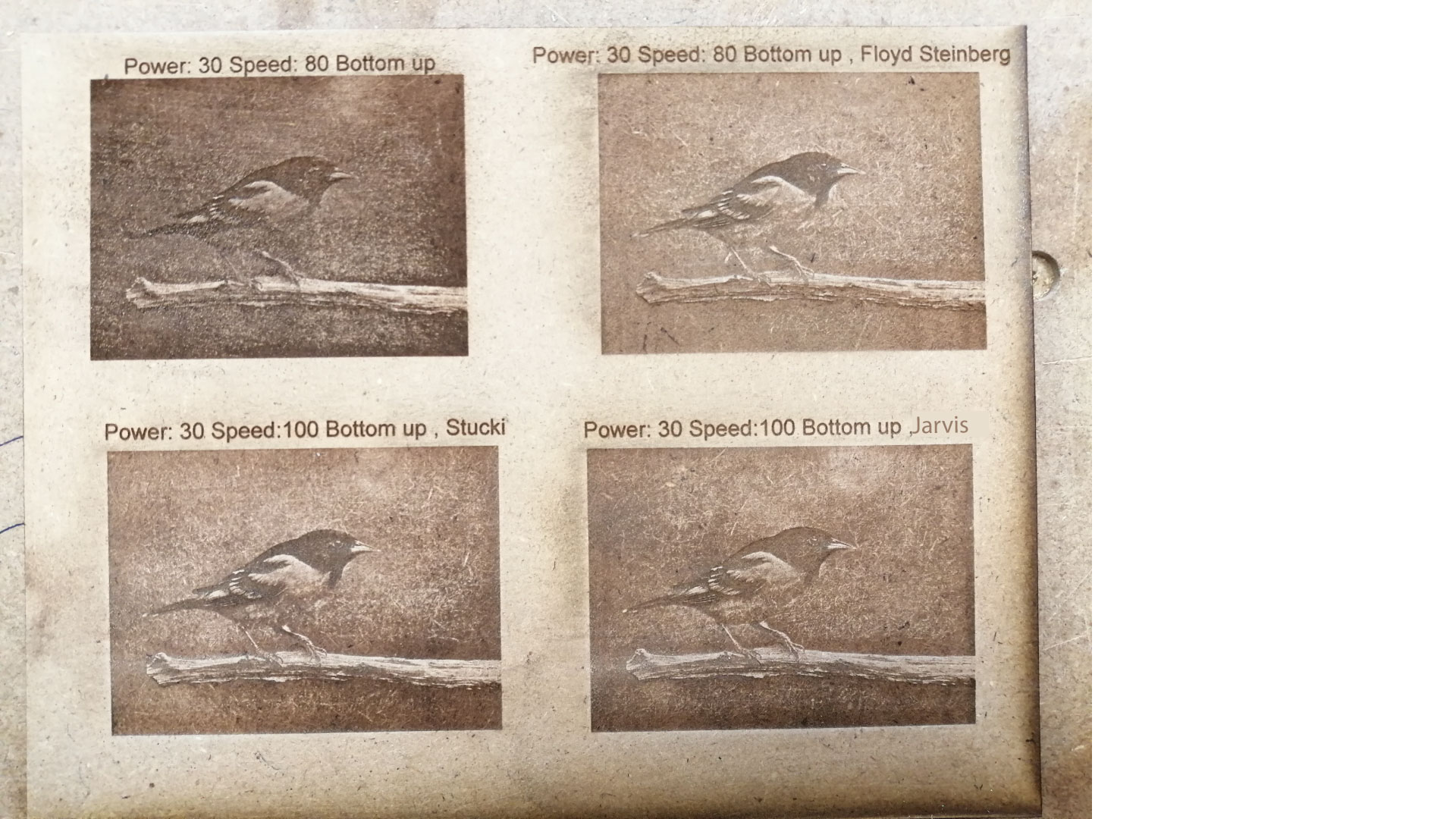
I wanted to try photo engraving with different image Dithering settings, to see how different the result would be with the exact same settings, only changing Image Dithering in each test.
I noticed that the "Stucki" method gives the best details for photo engraving, and I chose the engraving direction "Bottom up", which means that the laser cutter will start engraving the photo from the buttom-up, this will prevent dust being collected on the engraved photo.
Design and Constructing the press fit kit
the goal was to build a construction kit that can be assembled in different ways, and it must be press fit, meaning that no glue should be used to put the pieces together.
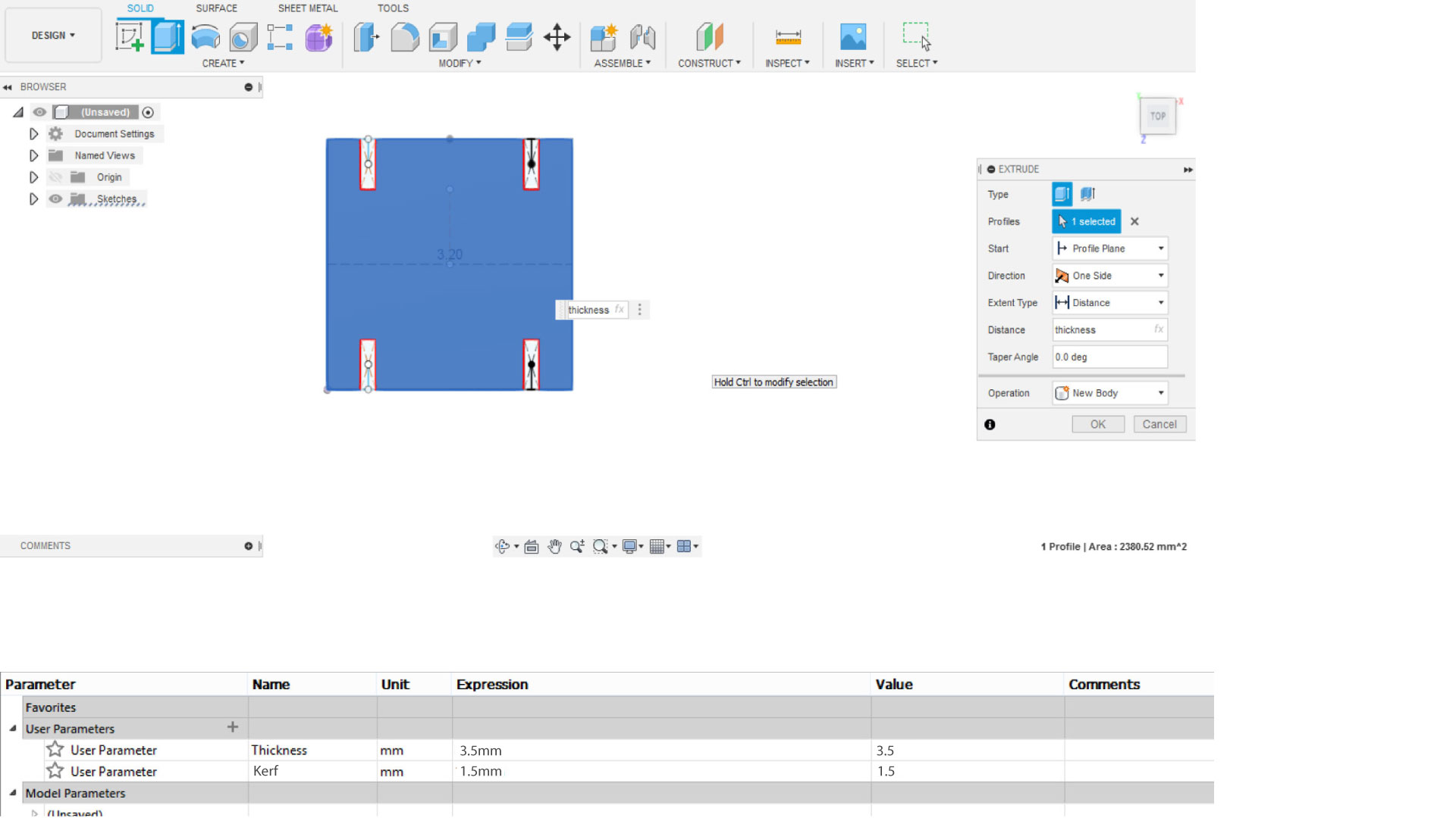
the press fit kit should be parametric, so that it can be cut on different material with different thickness and different kerf options.
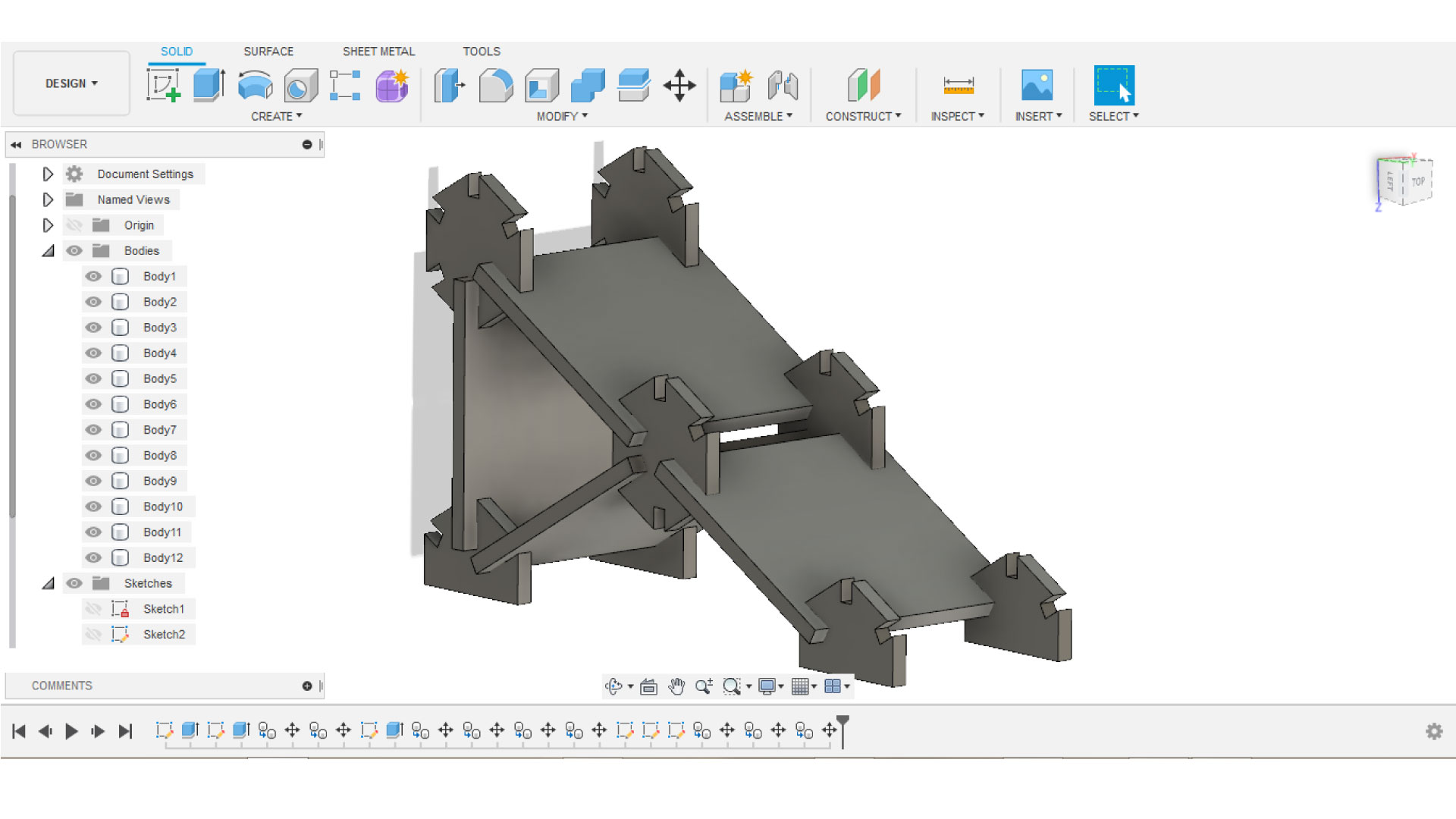
I used Fusion 360 to design my kit, and i added thickness and kerf as parameters that can be changed
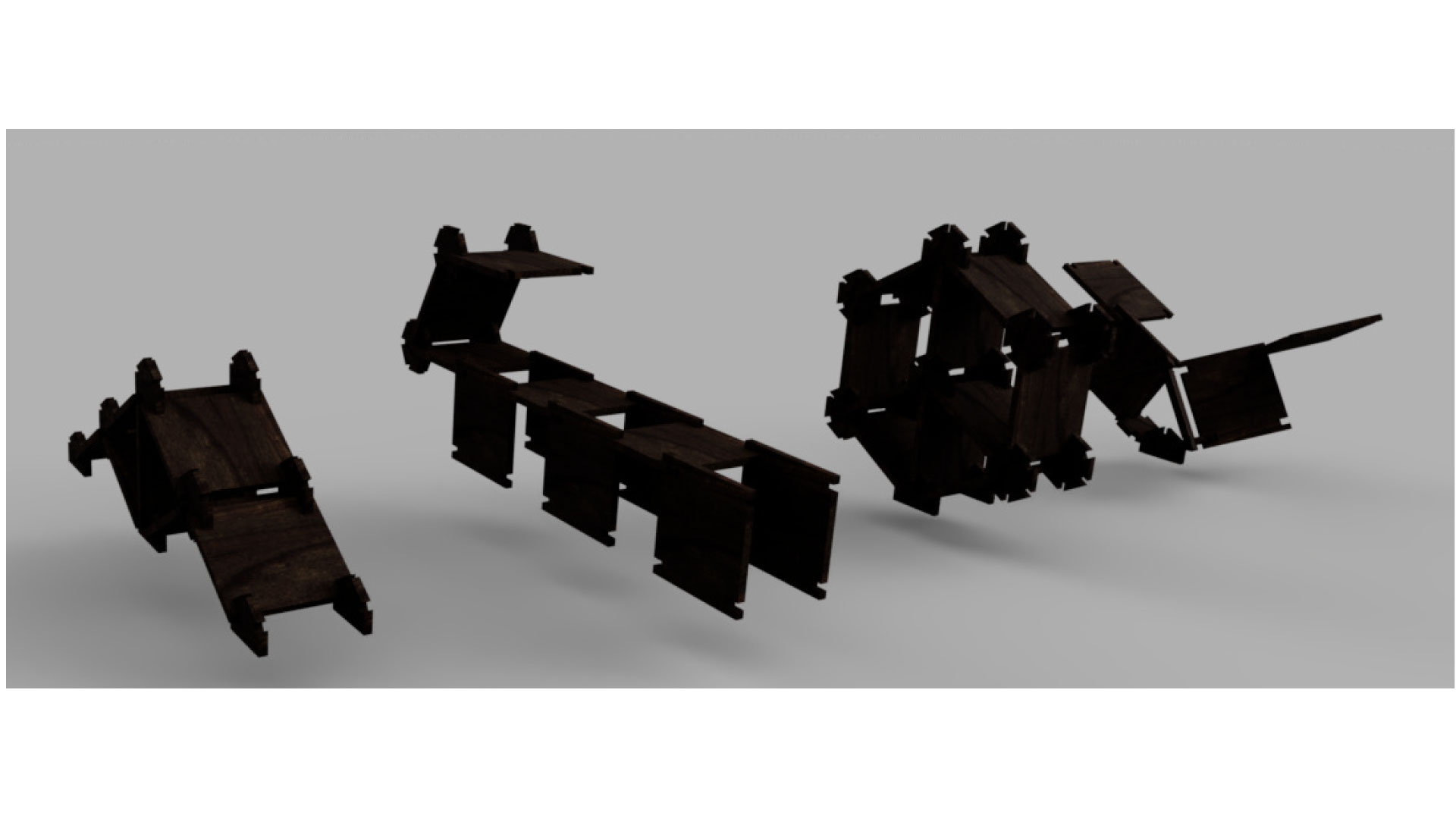
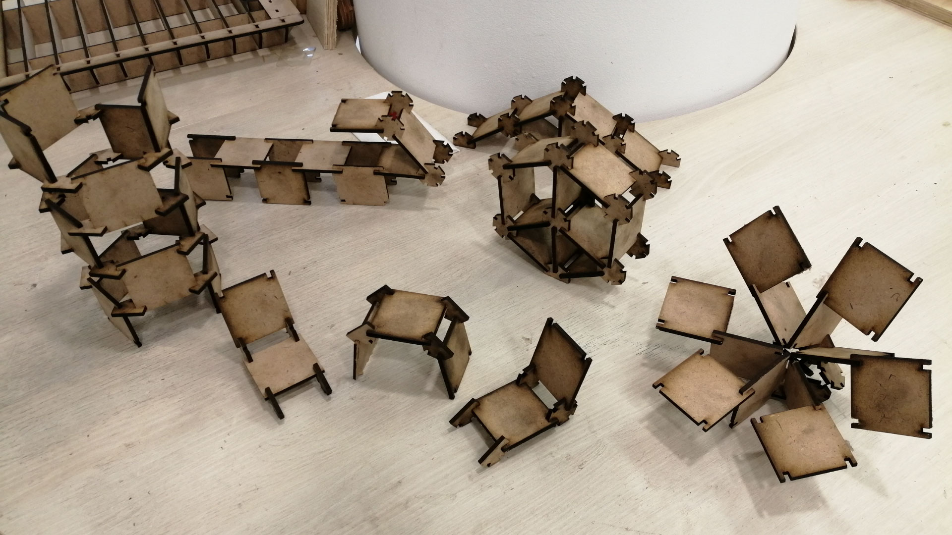
I made 3 pieces in different shapes to assemble the kit, then i assembled different shapes on fusion, like a bench, hexagon shaped shelf, a slide, and flower shaped chairs
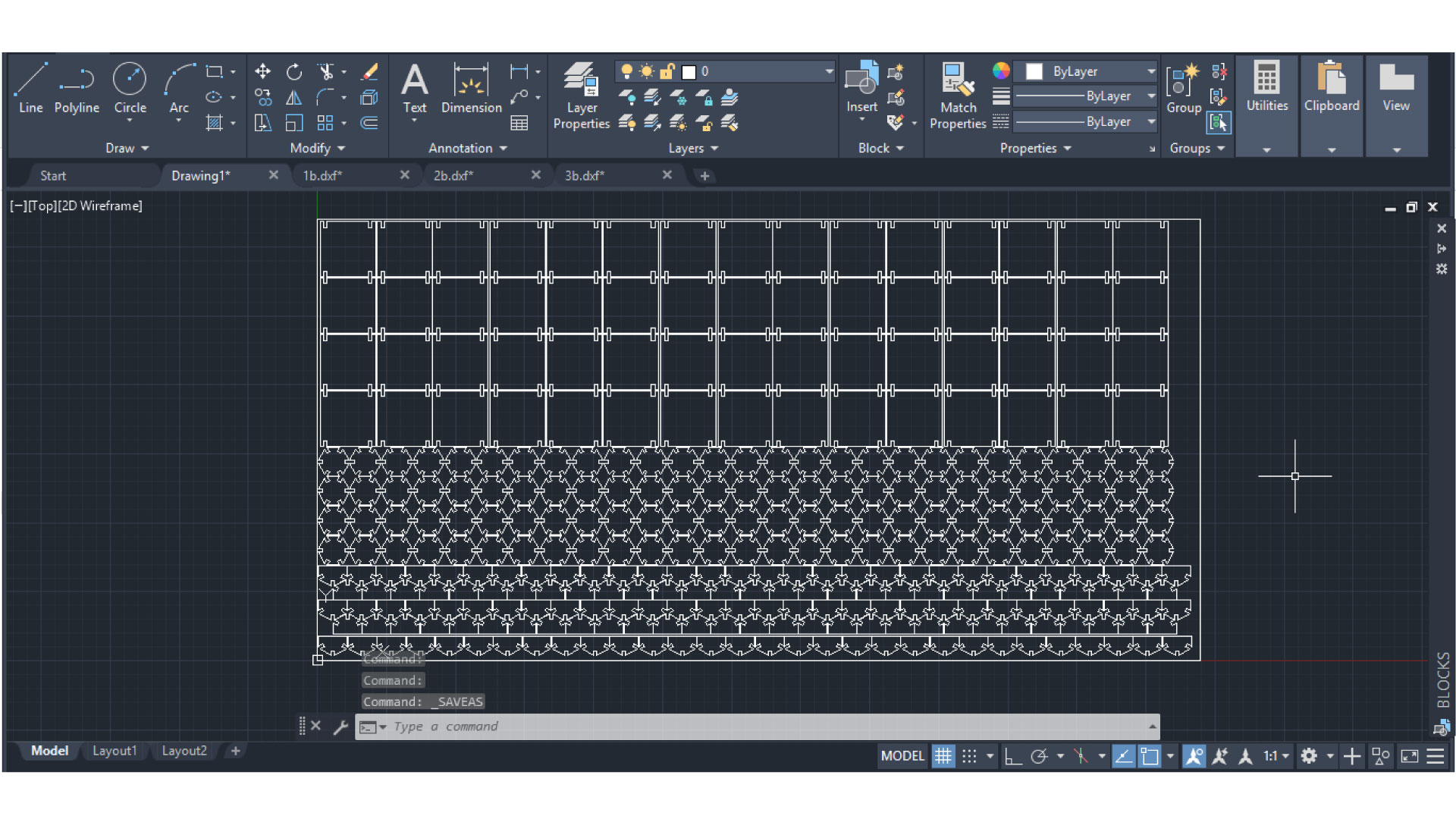
After that, i had to lay down the pieces on a 2D design using AutoCAD, to do so, i had to save the skitch of each part as .DXf, then i opened AutoCAD and i fitted the pieces on an 800mm x 400mm rectangle(the size of my board), and i saved the design as ".DXF 2007"
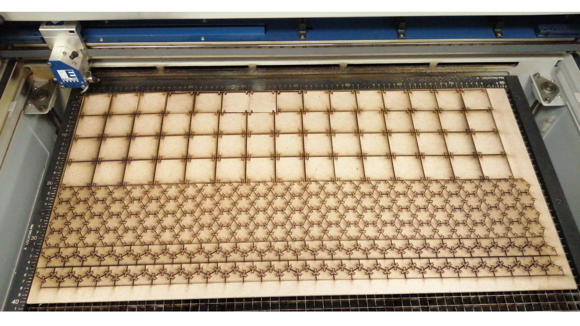
After that, I opened the design in Corel Draw, and i made sure all vectors are "Hair Line". I chose my laser cutting settings, and I forwarded the job to the laser cutter following the steps shown before.
After that, I press-fitted the parts to assemble different shapes.
Vinyl Cutting
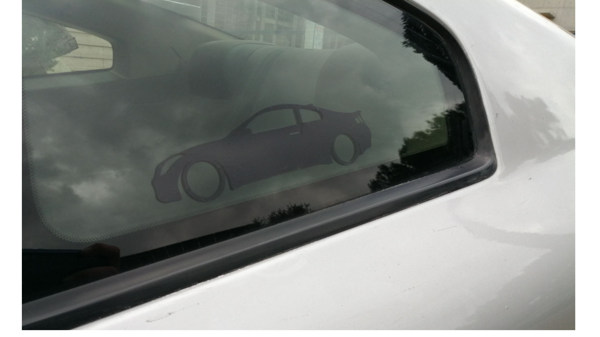
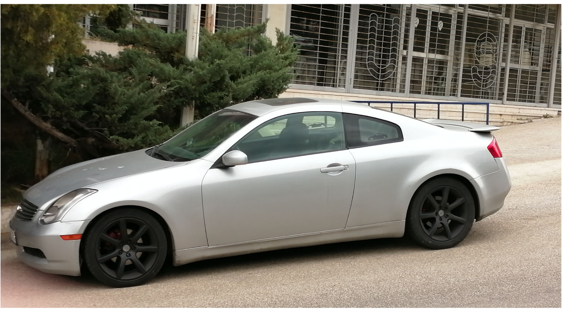
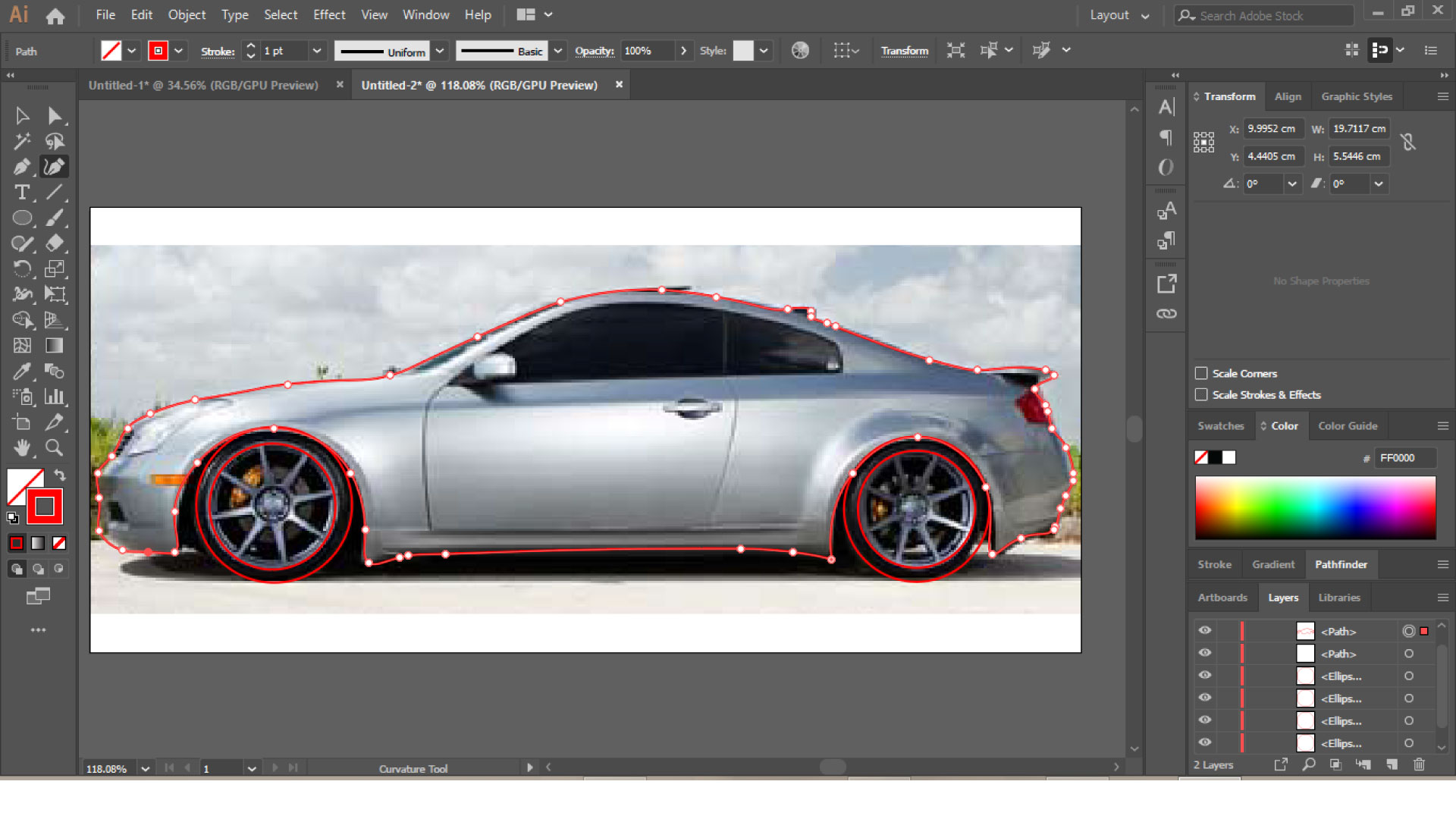
The other part of the assignment was to cut something on the vinyl cutter. I decided to design a decal to place on the side back window of my car, I designed the shape of my car using Illustrator by tracing a side view image of the car.
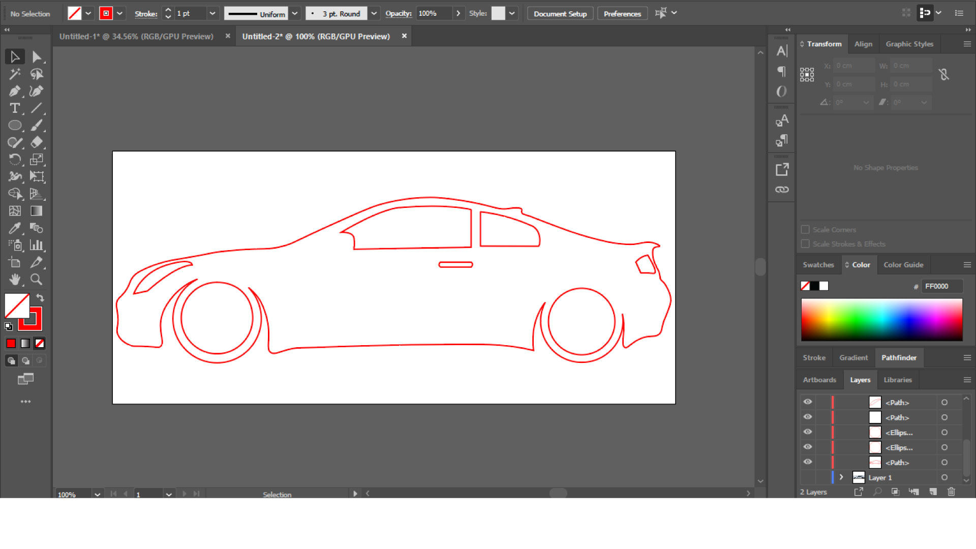
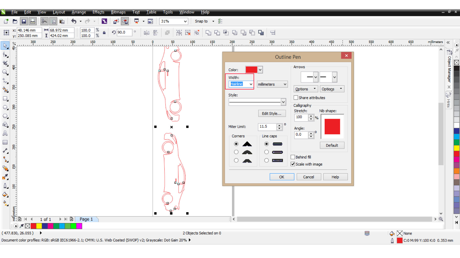
I saved my design as .EPS, thenIi opened Corel draw and placed the design, then i made the vector thickness as "Hair line".
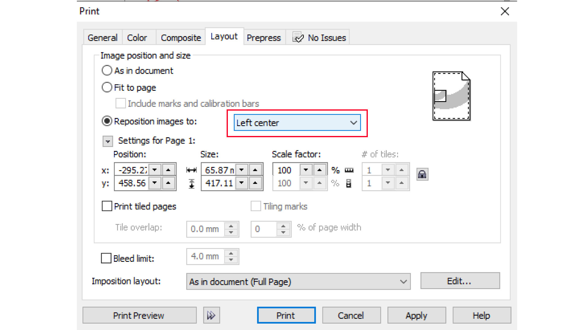
Then, pressed Ctrl+p to open the printing setup window, went to layout, and selected "left center".
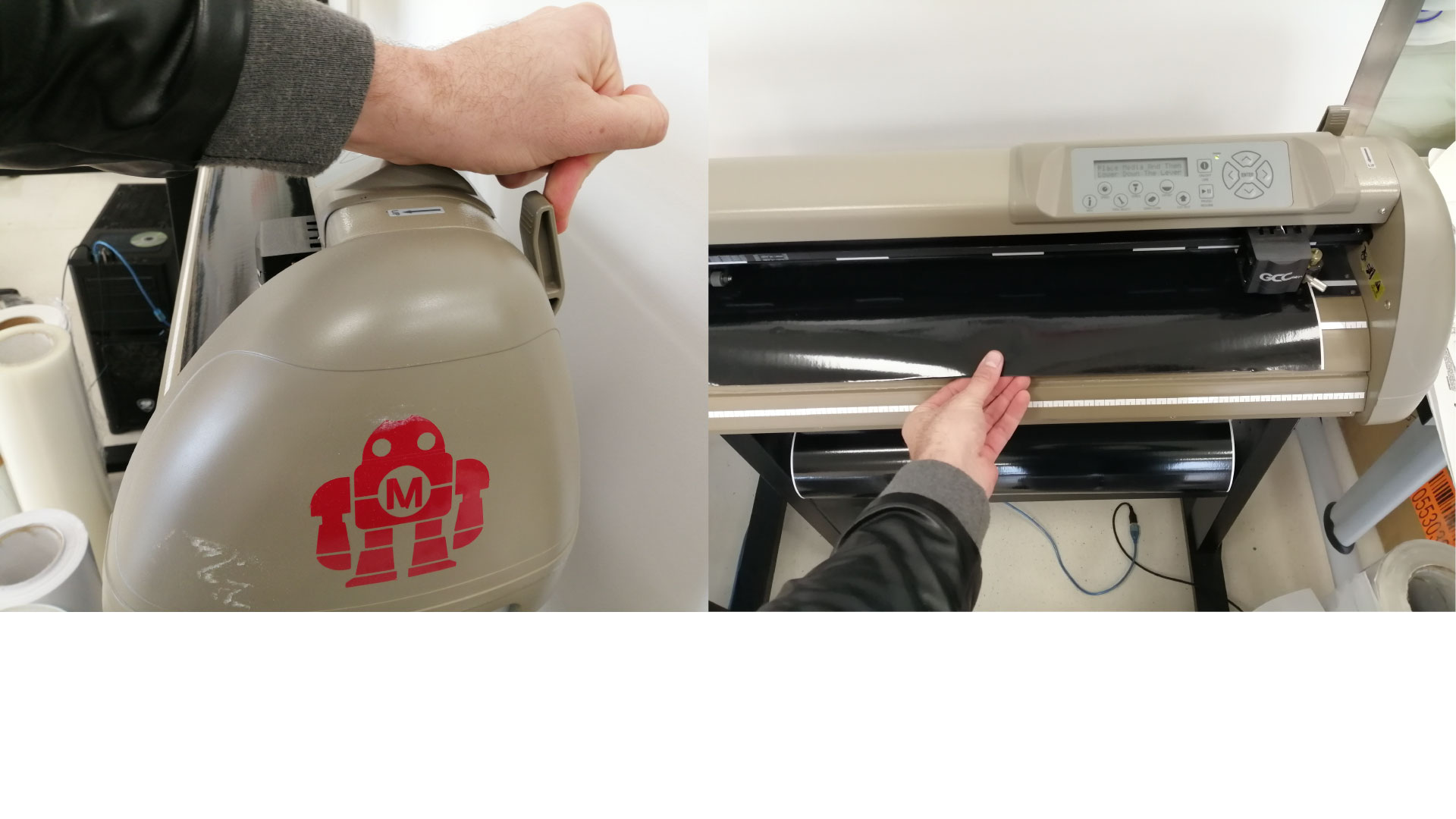
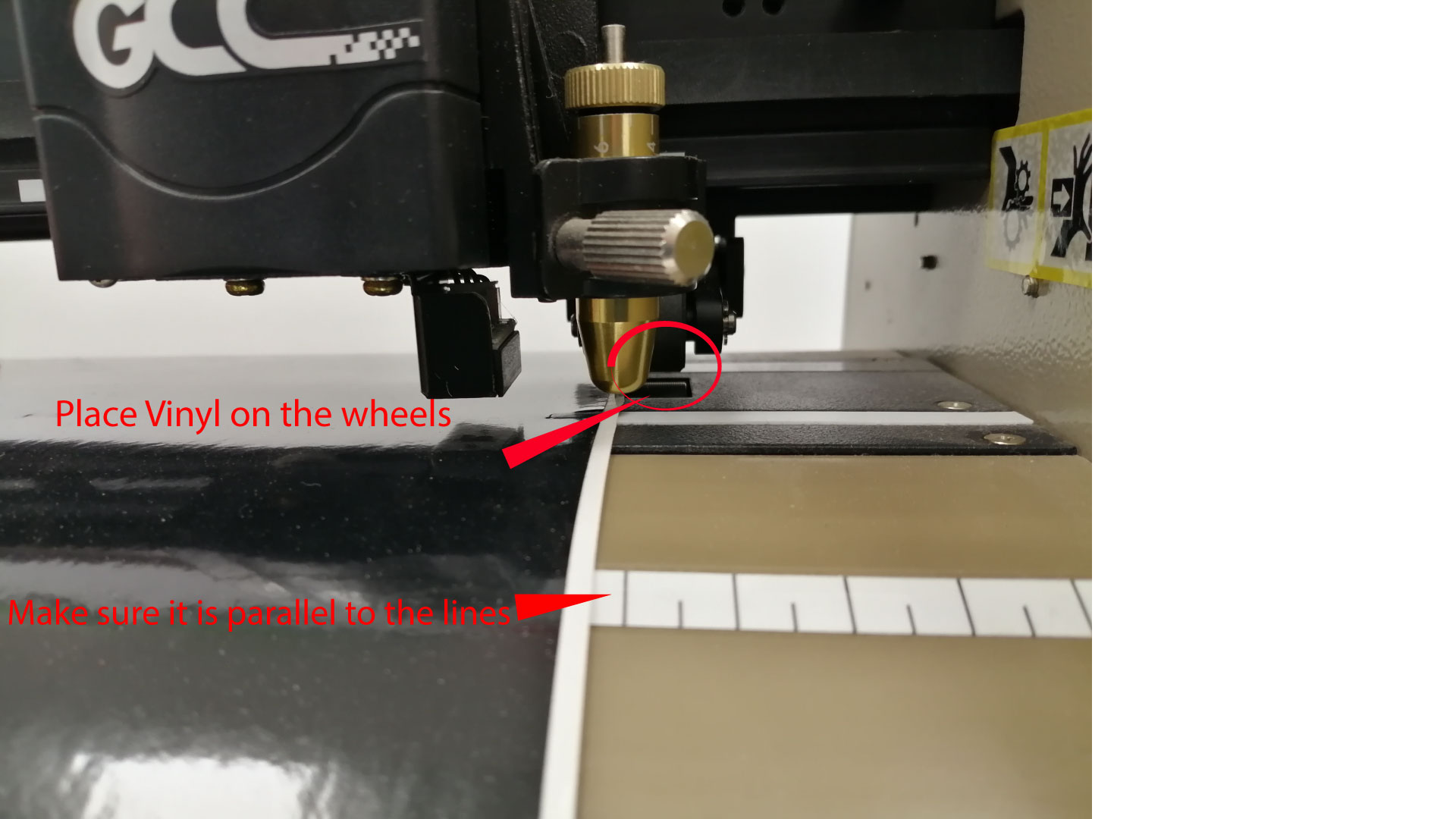
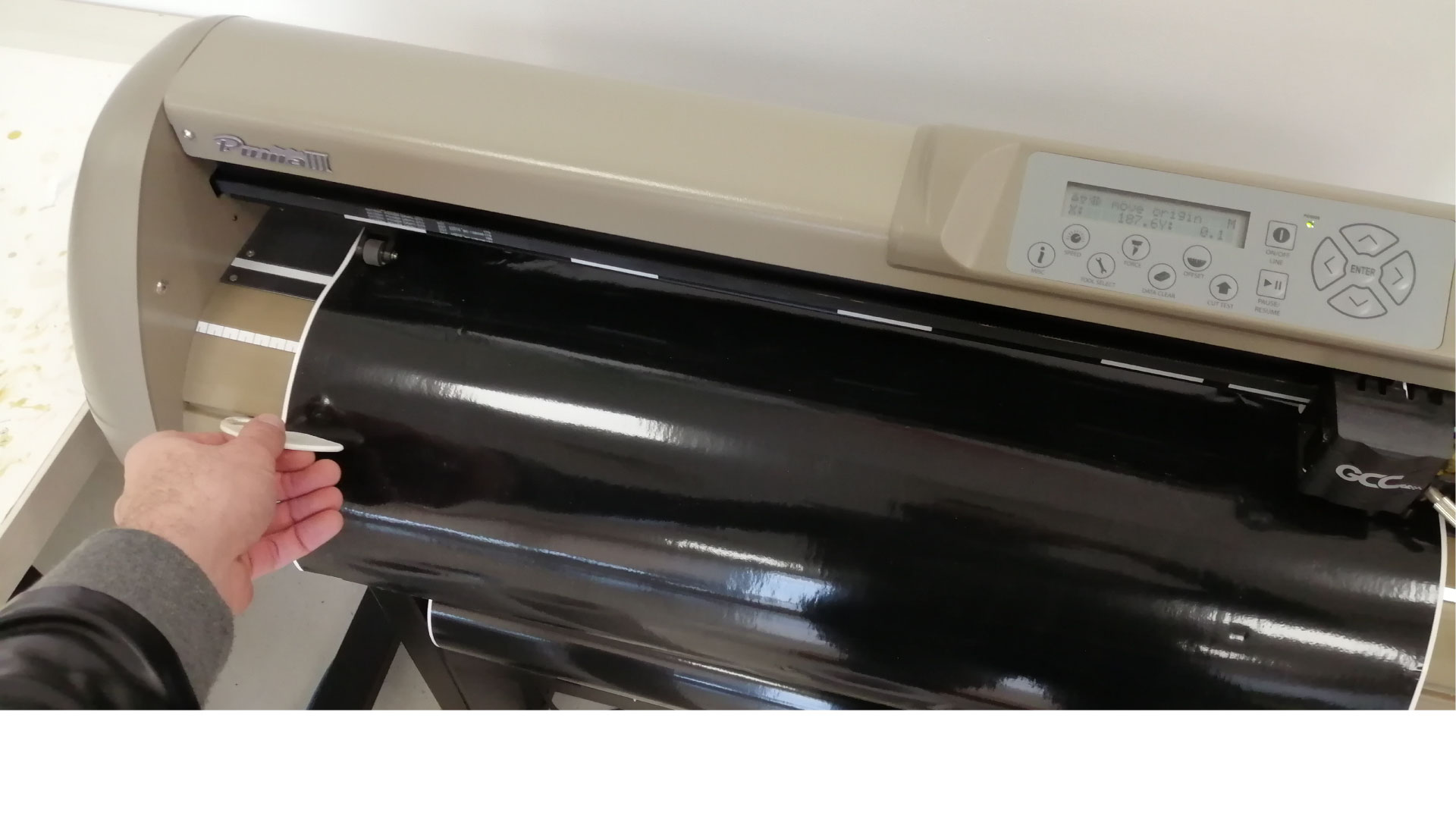
After that, turn on the vinyl cutter and wait for it to initialize. to load the vinyl to the machine, raise the pinch roller lever, and load the material from the back side of the machine (make sure that the vinyl is loaded parallel to the lines on the machine, and make sure that the material is on the wheels from both sides).
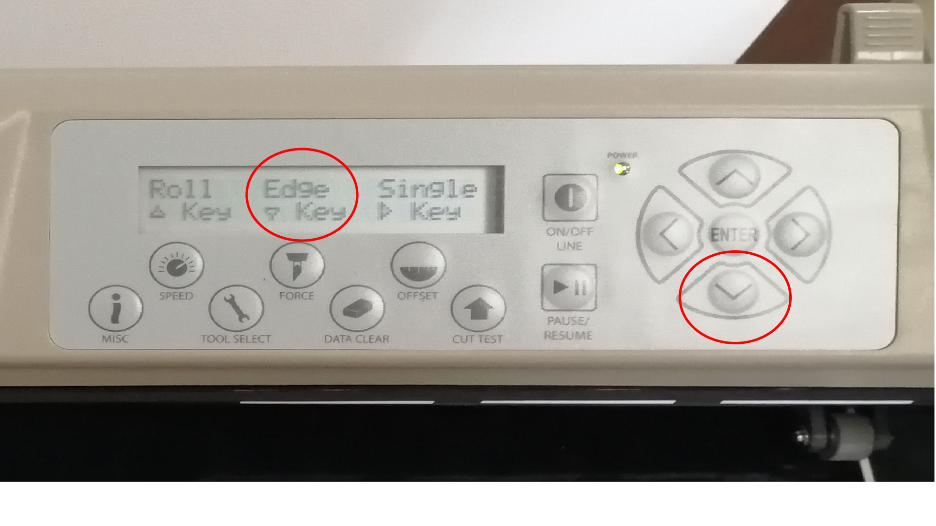
Now, select the "Edge" option from the control panel on the vinyl printer, it will measure the width of the vinyl placed.
And now, press print from the PC, the vinyl cutter will start the cutting job.
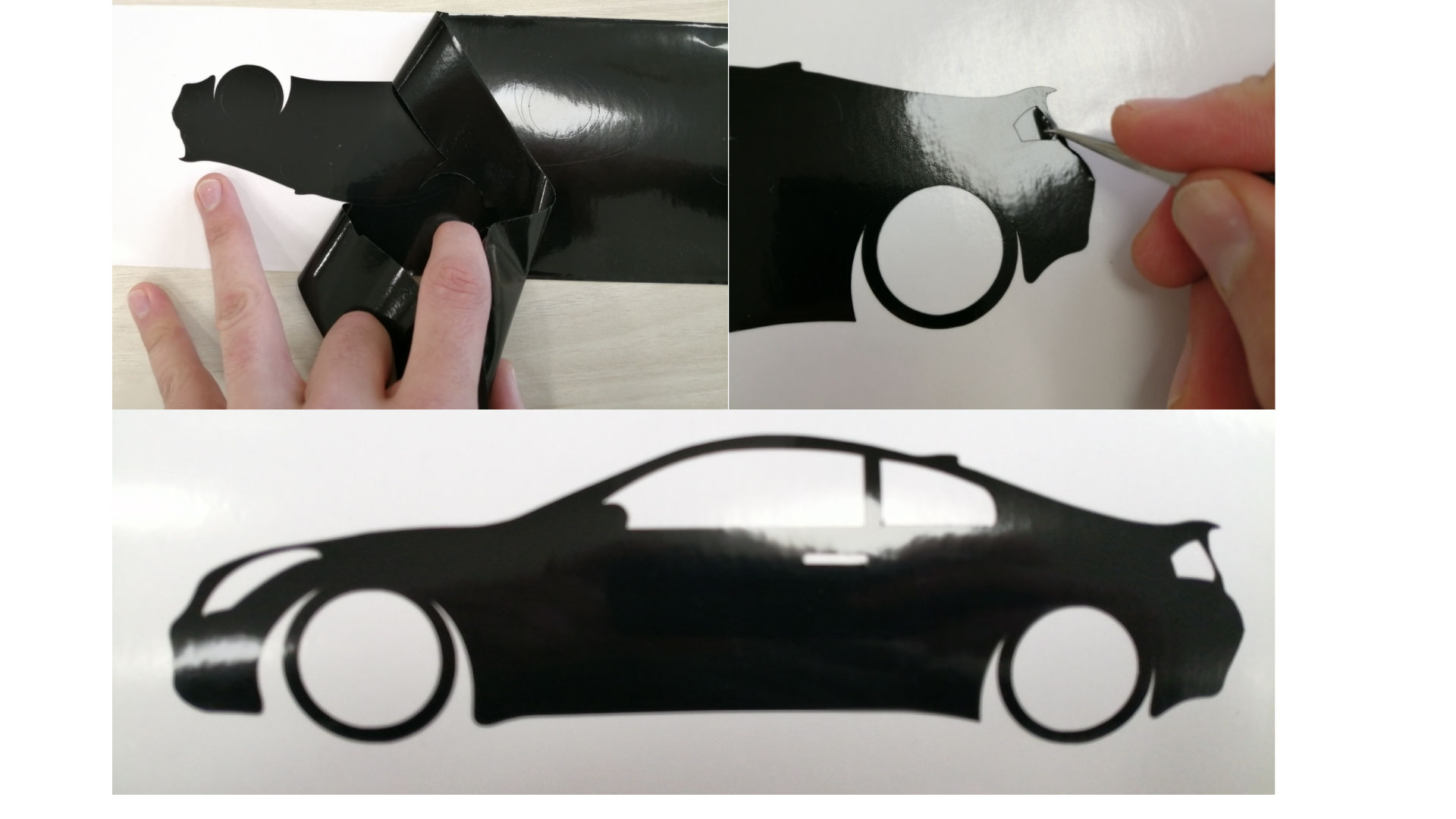
when done cutting, you can press the down arrow on the vinyl cutter to push the vinyl out, then grab the blade cutter to cut your design
Then, peel off all the extra vinyl that is not needed in the design, and place transparent adhesive film on top of it (transfer tape) to help transfer the design to the surface we want to place it on.
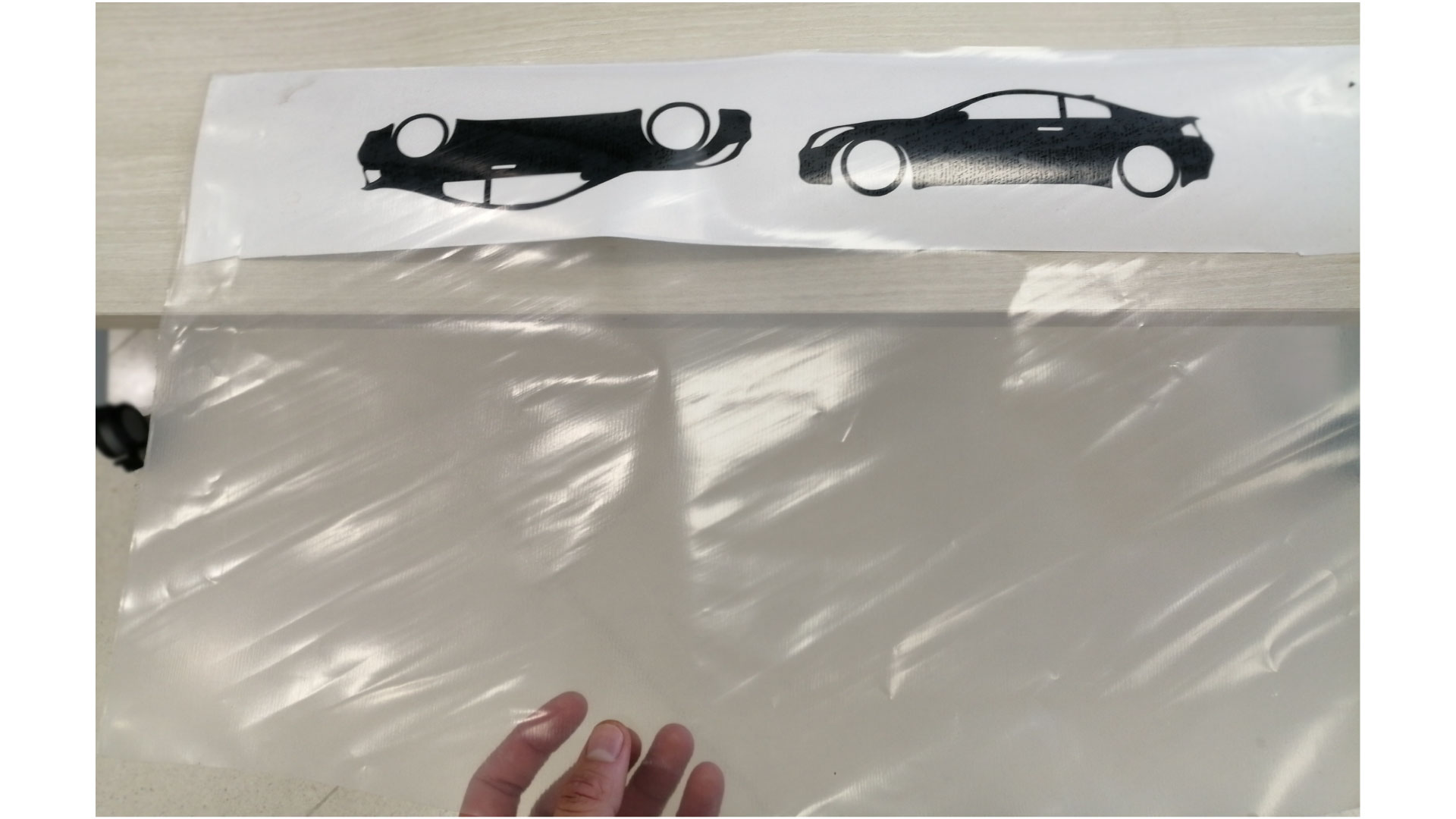
I cleaned the back side window and placed the sticker on it, then removed the transfer tape carfully.