Computer Controlled Machining
Assignment:
Group assignment:
test runout, alignment, speeds, feeds, and toolpaths for your machine.
Individual assignment:
Make something big.
Introduction
What is CNC milling?
the CNC or (Computer Numerical Control) uses the subtractive manufacturing technology to create objects, which means that it removes material using a variety of cutting tools from raw material (wooden boards for example) in specific pathes defined by the designer to create objects.
Computer numerical control is programmed code that gives orders to make precise movements for the machine to follow.
There Are different types of CNC machines, defined by the number of moving axes:
2-Axis can cut holes in the x- and z-axes.
3-Axis most commonly used (the one we use), it can cut in the X-Y-Z directions, but it cannot reach the sides of the working piece.
4-Axis can rotate the X-Axis like the lathe machine, giving the ability to create more complex parts
5-Axis can rotate in both the X-and Y-axes. it gives the ability to create extremely complex structures.
For this assignment, we will be using the shopBot 3-Axis milling machine, but before we start, there are important things we need to understand:
-Different types of cutting bits
-Feeds and speeds settings
-Tool paths
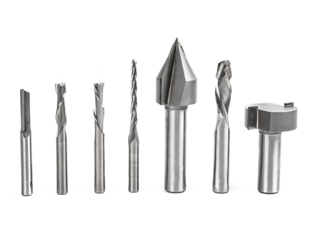
CNC Bits (cutting tools)
There are different types of milling cutters that can be used for specific different machining jobs.
Drill bits are designed to drill verticallyinto material, making cylindrical holes.
End mill bits are designed to cut cut along paths not just plunge vertically.
Some important factors we need to know to choose the tool and its settings like the Diameter, the Tooth the Flute, and the Cut Direction.
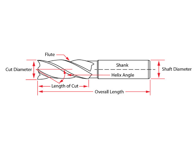
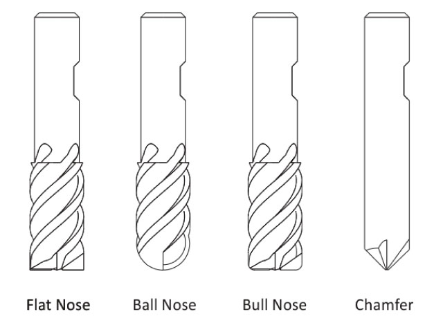
The diameter defines the thickness of the cut, the head defines the shape of the cut, there are different types of endmills like the ball nose, the drilling bit, the straight bit, it depends on what result you want to achive.
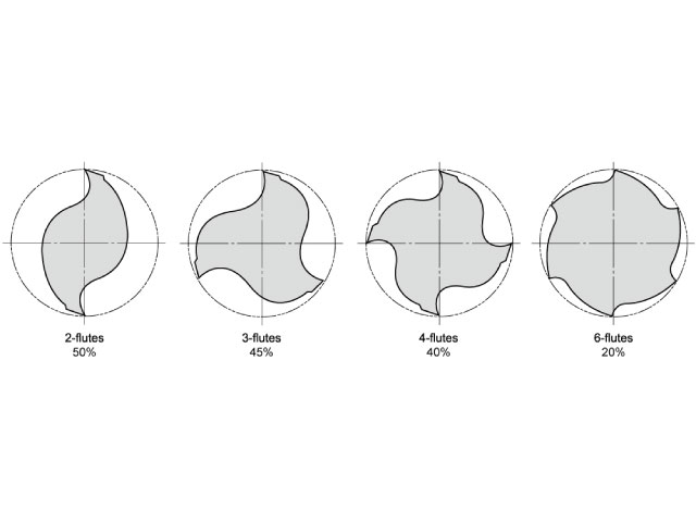
Flutes are the cutting edges of the end mill, there are different bits with different types of flutes, each has its unique properties.
There are also different types of cutting tool edge finishes, like the upcut bit, and the downcut bit
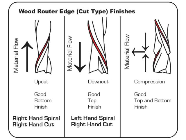
Upcut routers move material up and promote a good workpiece finish on bottom, Downcut routers move material down and promote a good top finish, Compression routers move material inward, as a result this promotes a good top and bottom finish.
Chip load charts:
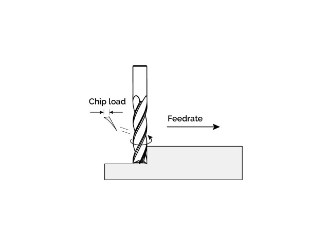
Chip load rate is measuring how thick the material removed by each cutting edge during a cut is. It is a very important factor when calculating the best settings for the endmill. Calculation are as follows: Chip Load = Feed Rate (inches per minute) / (RPM x number of flutes).
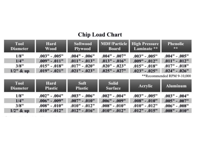
It is always adviced to visit the website of the manufacturer of the specific end mill you are using to refer to their recommended settings.
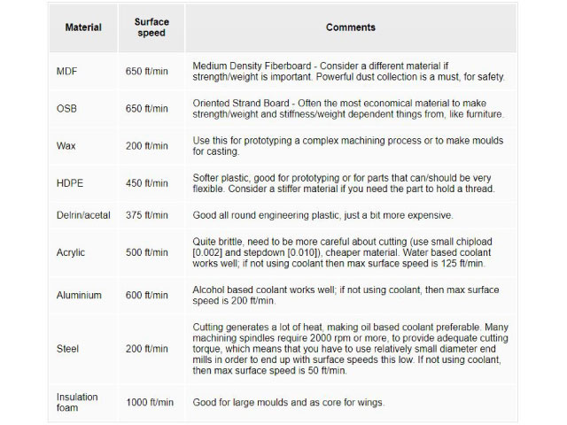
Feeds and speeds
Speeds refers to your spindle rotational speed in rpm (round per minute). the right speed should keep your tool from overheating while cutting.
Feeds refers to the machines linear speed in mm/min. Optimizing your feed rate is all about maximizing how much material you’re cutting per unit of time, without putting too much force on your bit.
We want to optimize the settings, to get a better surface finish and to have a longer tool life.
So, getting your feeds & speeds right means finding the sweet spot where your tool is spinning at the perfect speed relative to its moving speed inside the material.
when you reduce your spindle speed too much relative to the feed rate. Doing so, you’re forcing the flutes of your end mill to cut off too much material, which can lead to unwanted vibration or worse, a broken tool.
if you reduce the feed rate too much relative to spindle speed, the flutes of your end mill will start rubbing the material instead of cutting nice chips. This action will make your tool overheat, and thus soften. Its sharp edges will become dull and if you keep cutting with dull edges and you will start to see a very deteriorated surface finish on your material.
A good rule of thumb is to always remember that you need to make chips, not dust.
Chipload = Feedrate / [RPM x number of flutes]
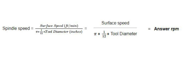
Important equations to calculate the spindle speed and the Feed Rate for the desired job.
Spindle Speed
Feed Rate
Feed Rate = Spindle Speed (RPM)* Number of Flutes * Chip Load (inches) = Spindle Speed * Number of flutes * Chip Load = Answer inches/min
Plunge rate
Use a plunge rate of 50% or less of the feed rate.
TEST RUNOUT, ALIGNMENT, SPEEDS, FEEDS, AND TOOLPATHS FOR YOUR MACHINE
Test 1:
We used 10 mm MDF for our tests, and 6 mm bits.
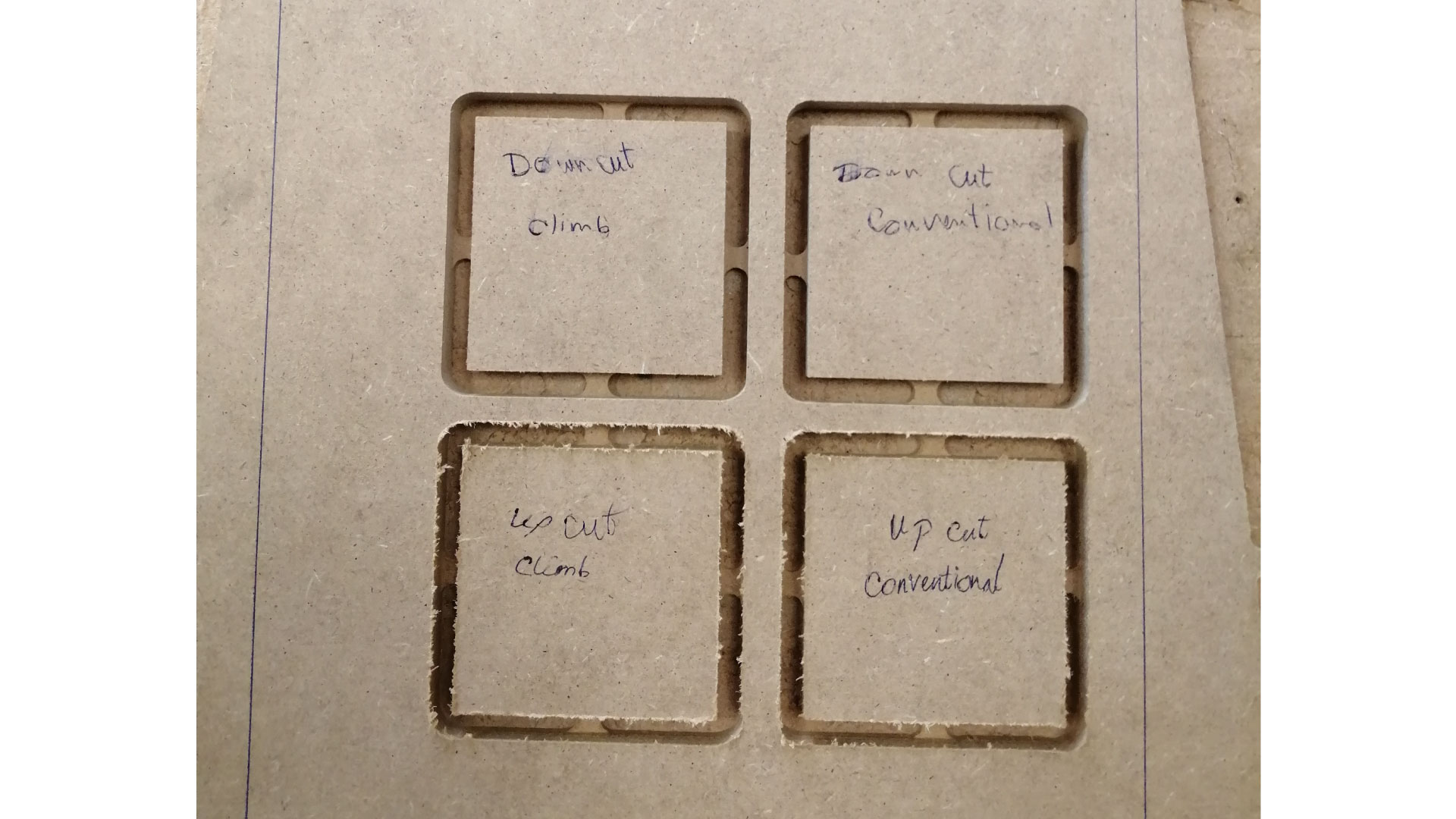
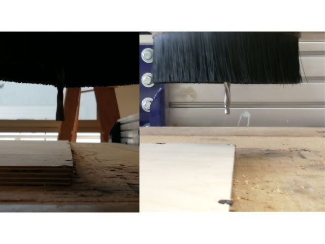
In this test, we used an up-cut 2-flute bit, and a down-cut 2-flute bit, and we tested both for conventional and climb paths. We noticed that the down-cut bit had a smooth finish at the top, but the bottom had rough edges. The up-cut bit gave opposite results to the down-cut bit, with the bottom having the smoother edges. we have not noticed a difference between climb and conventional cutting for our test.
Test 2:
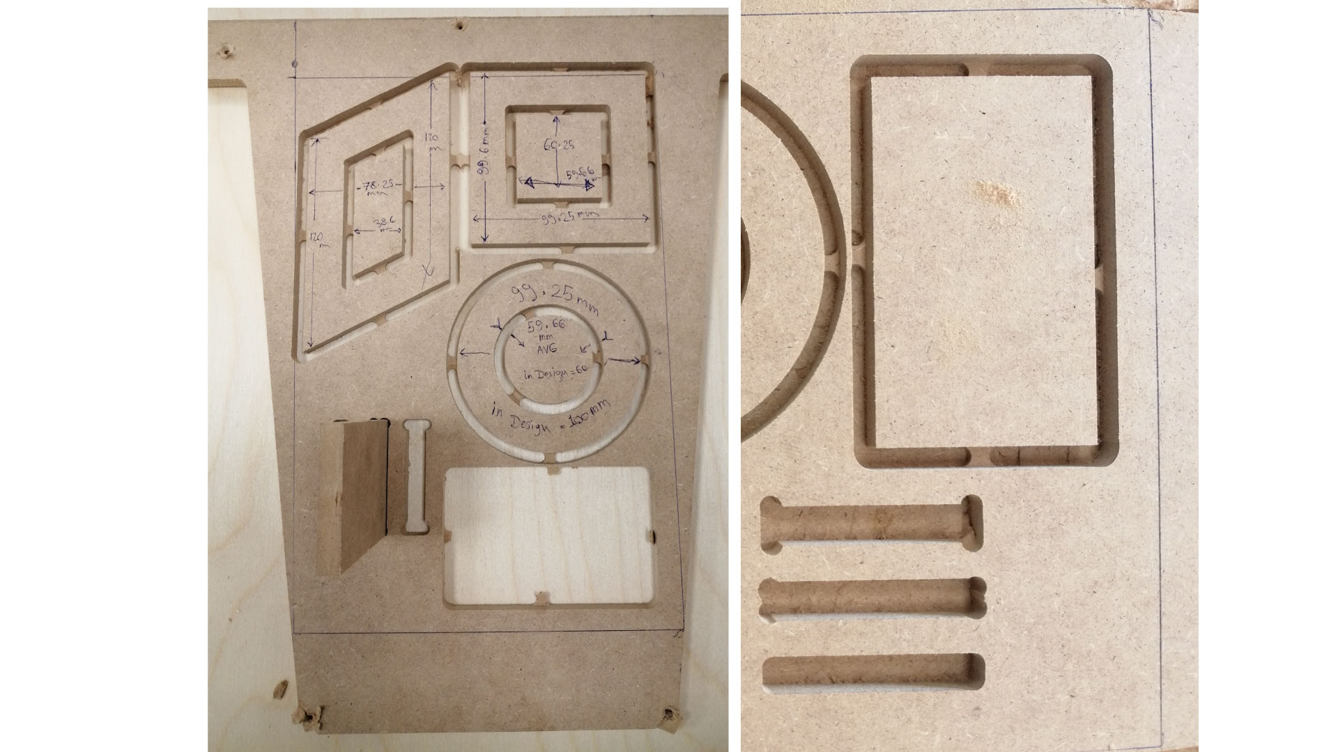
For the second test, we designed a 100mm x 100mm square, with a smaller (60x60) square inside of it, and a 100x100 circle with a smaller 60x60 inside. We measured the dimensions after cutting, the results for the square show that there is a 0.75mm difference in the X-direction, and a 0.4mm difference in the Y-direction. The results of the circle show that there is a 0.75mm difference for the outer circle, and a 0.34 mm difference for the inner one. We also tested T-bones with different depths, it is not possible to fit our piece in the slot without T-bones.
MAKE SOMETHING BIG
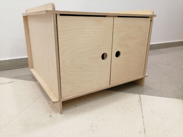
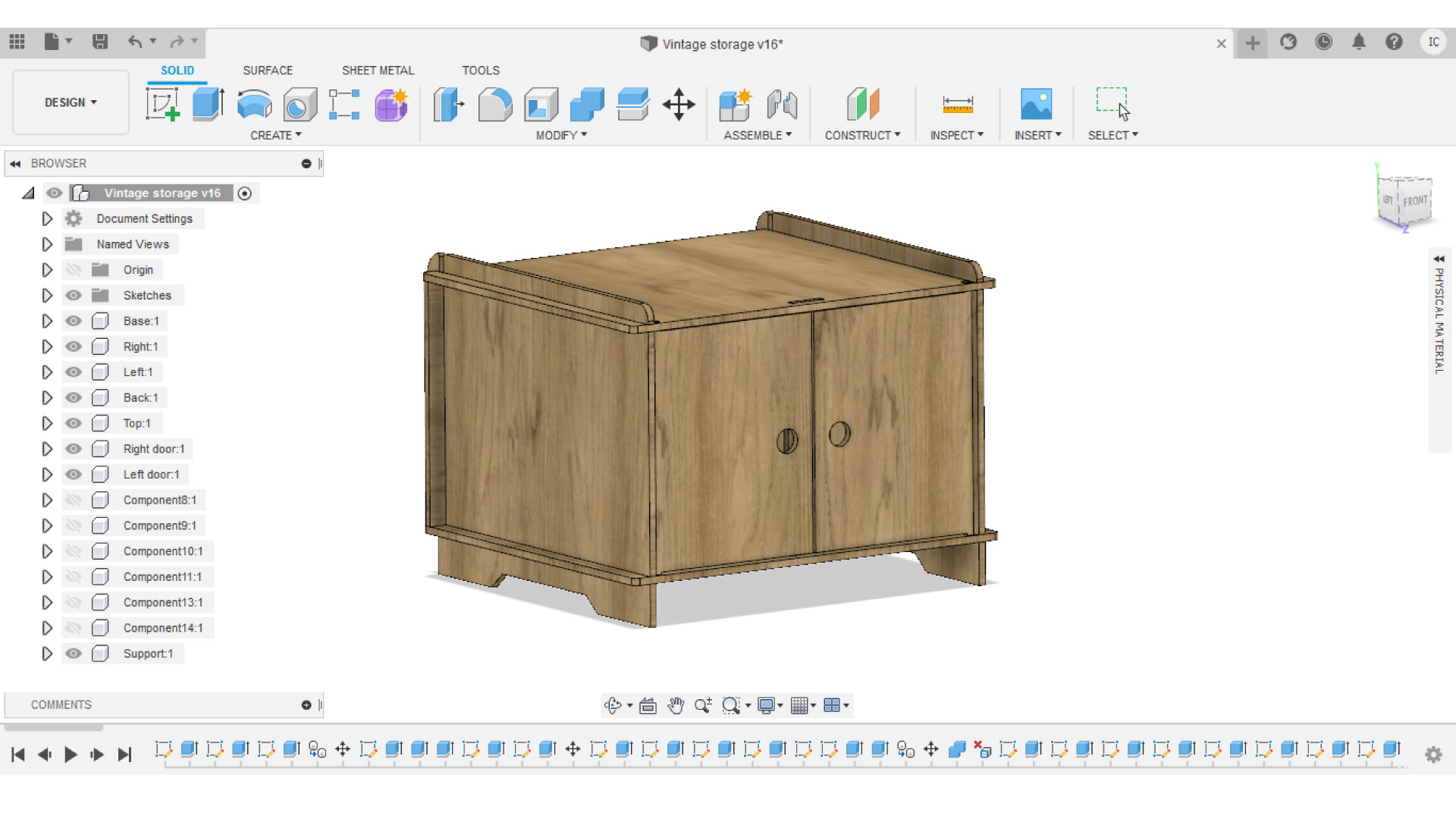
For this weeks assignment, i wanted to design a low storage unit with a simple design, and my goal was to create the storage unit to be press-fit, meaning that there will be no need for screws nor glue to put the unit together.
I decided to use 12mm plywood for the assignment, so i ran multiple joins and fitting tests to be conducted in my design.
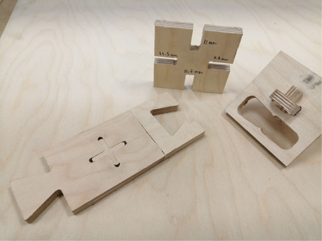
I wanted to test a locking mechanism incase i needed it in my design, and I wanted to do a press kirf test to decide how tight I should make my slots to make the assembly press fit, and I also done two different joints that may be used in my design
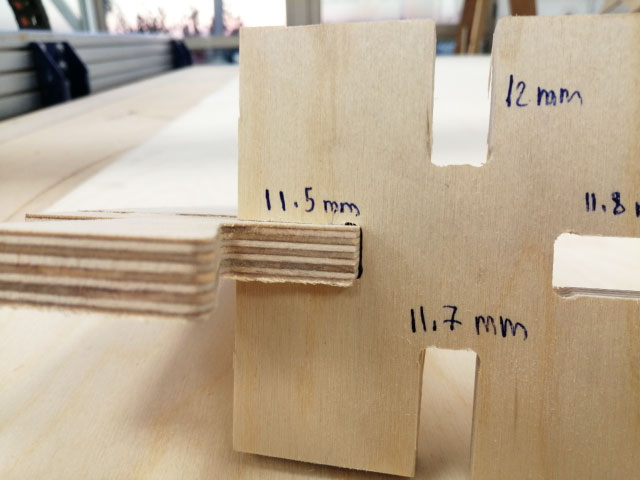
For the fitting test, making the slot 5 mm tighter gave the best fit for my pieces, it is tight enough to keep the pieces in place.
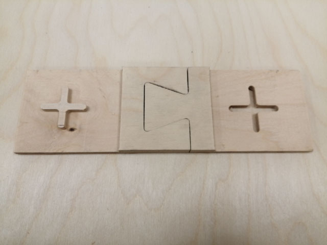
This joint fits perfectly and it attaches secures the pieces together very well.
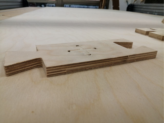
This cross-shaped joint is made by ingraving the two sides to half the thickness, keeping the cross on one side, and milling the cross on the other. this joint is extremly strong, once it is put together, it is really hard to take the pieces apart.
DESIGNING THE UNIT
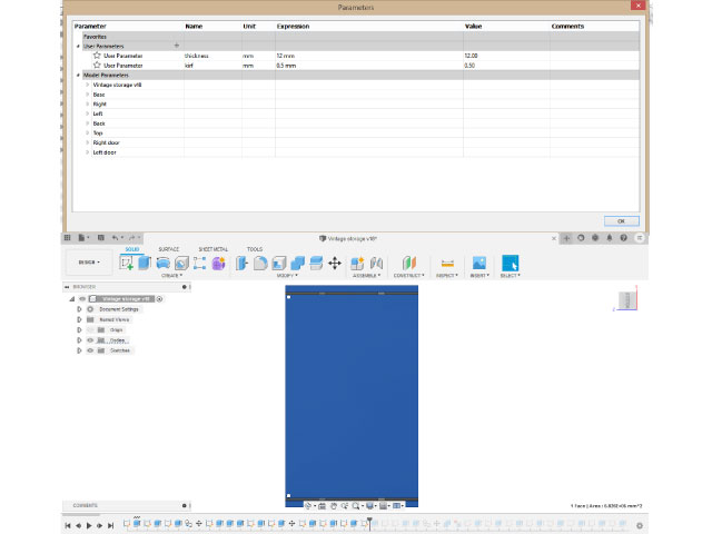
I added my parameters to the design based on the tests (kirf and board thickness), and i kept in mind that The board dimentions are 2440 mm x 1220 mm
Then I double checked all the components of the design, and made sure that all the slots have T-bones on the edges to make sure pieces will fit, and I planned how to assebly the unit.
Then I layed down my components using the arrange feature in fusion 360, which allows us to choose all the components, and set the dimentions of the plane we want to lay them on, as well as choosing the spacing between the components on the plane and the borders
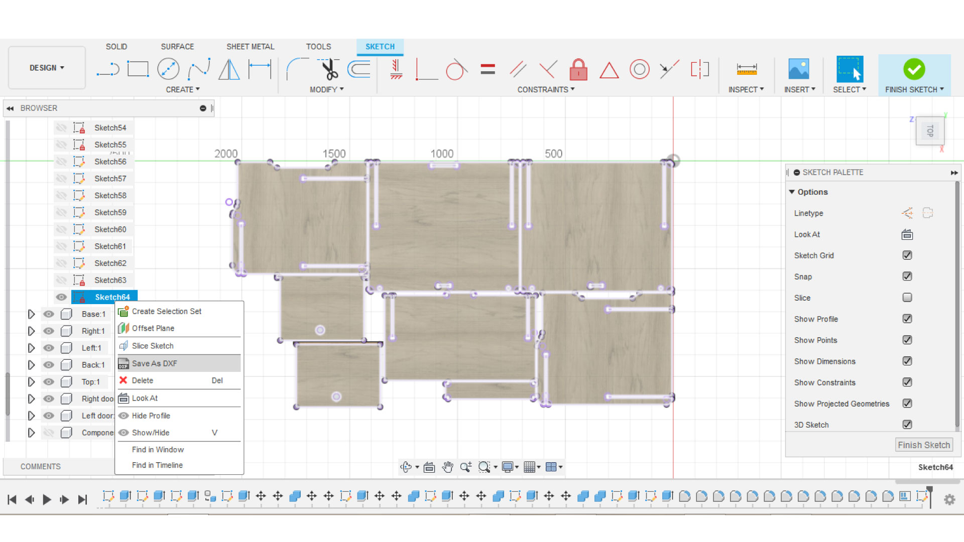
After that, I created a sketch on the pieces and exported it in .DXF format, I opened it in AutoCAD just to double check.
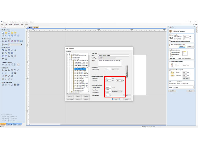
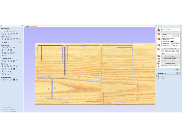
Then, I opened Vcarv, set my board dimentions, and loaded my vectors to the software. After that, I selected my tool settings based on the calculations, for this assignment I used a 6 mm downcut 2 flute end mill.
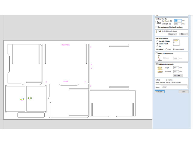
Then I selected the inner outlines, and created Inner paths, meaning that the cnc will cut inside the closed vector. I added tabs to hold pieces in place otherwise they will fly off the board.
Then I selected my outer vectors and created outer paths to cut from the outside of the closed vectors.
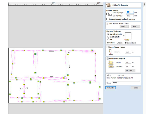
After that, I previewed the milling job on Vcarv, and the timing of the job showed on the software that it will take 16.5 minutes to perform the milling.
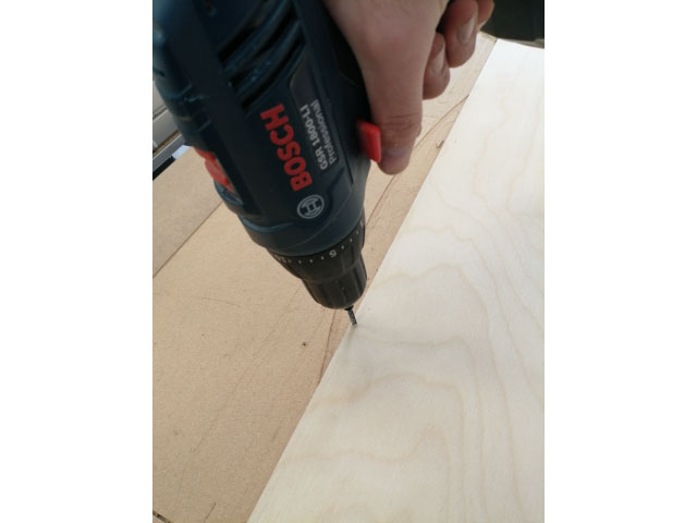
Then, I placed my board that has the dimentions of (2440 mm x 1220 mm x 12mm) on the shopbot, and secured it by screwing all the sides. Make sure to be ontop of the board while screwing the sides otherwise the board might be lifted from the center causing parts to fly off the board.
Note: you must take into concider the screws while designing, meaning that you must leave at least 2 cm gap for all the boarders of the board, otherwose, the end mill will hit the screws and break.
Then I saved the G-code on a specified folder, and I opened shopbot software to set my x-y-z zeros.
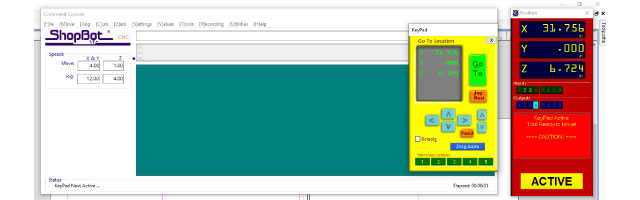
first, make sure that there is no obstacles in the way of the machine, then we can move the XY axis to set our zero, we always set the zero point at the lower right corner of the CNC (if you are looking at it from the front). Place the bit you want to use before zeroing. then move to your zero and press Zero axes on shopbot software, and select X and Y only.
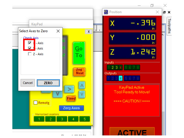
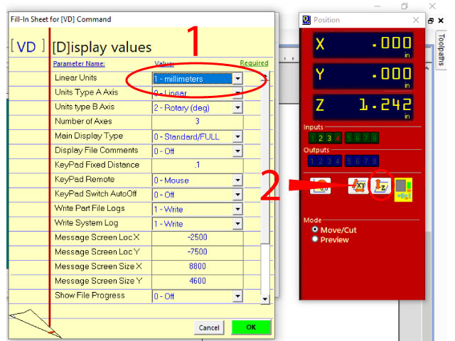
Now that we have the X and Y axis zeroed, we want to zero the Z-axis. First type "VD" on your key board, and change to mm, then select Z zero
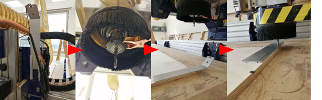
Before hitting "Enter" Place the Z-zeroing alligator on the tip of the router as shown in the image, and underneath it place the zeroing metal pad. When the end mill touches the pad, it will know that this is the zero point.
After placing the alligator and the pad, press enter on the PC and quickly go back and make sure the metal pad is flat on the board and keep it in place, once the zeroing is over, you will see a message on the PC telling you to remove the clip and the pad, and put them back in place, do that and hit enter.
type "VD" on your key board, and select inches. Now we have X-Y-Z zeroed, we are ready to start milling. Load the G-code you generated using Vcarve to shopbot and press enter, you will have a message telling you to run the router before starting the job,
Put on the safety goggles, and make sure to keep a distance from the machine when the job starts
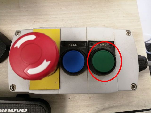
Wait for approximately 2 minutes letting the bit warm up. turn on the dust collector, then press enter on the PC.
Now the job should starts, keep an eye on the machine incase something goes wrong.
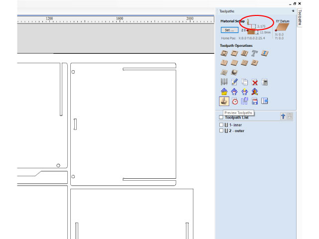
In my case, something did go wrong, there was a problem in the G-code, causing the router to go down when transitioning between vectors
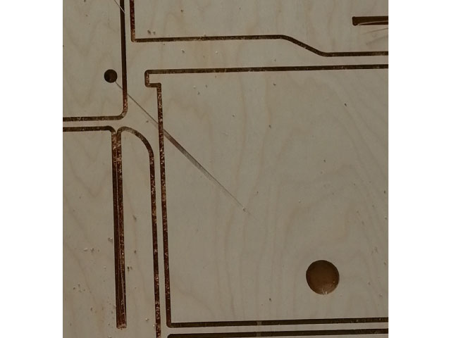
We fixed that problem by increasing the z height between transitions from 3 mm to 5 mm.
Then we completed the milling job
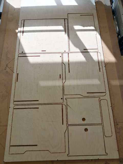
After that, I vacuum cleaned the board to get access to the Tabs
then i started cutting the tabs
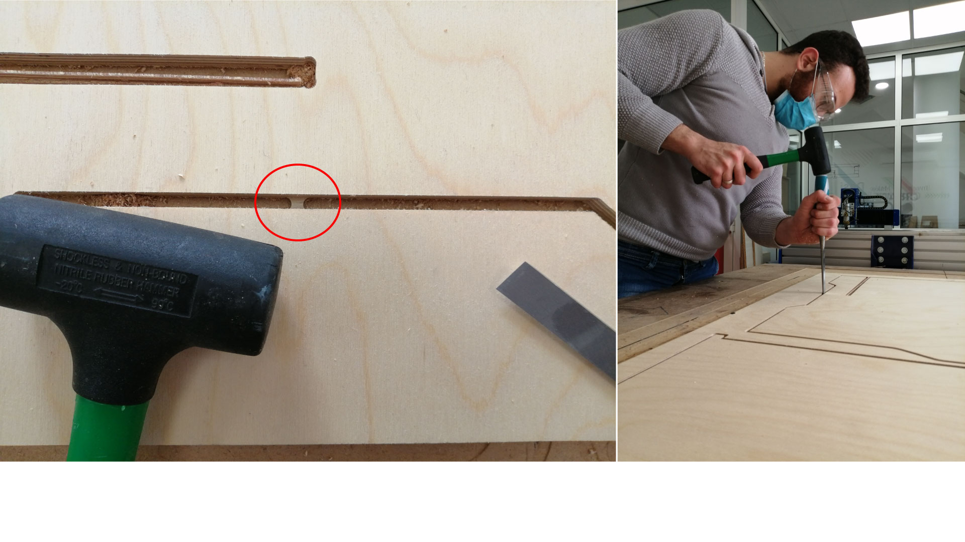
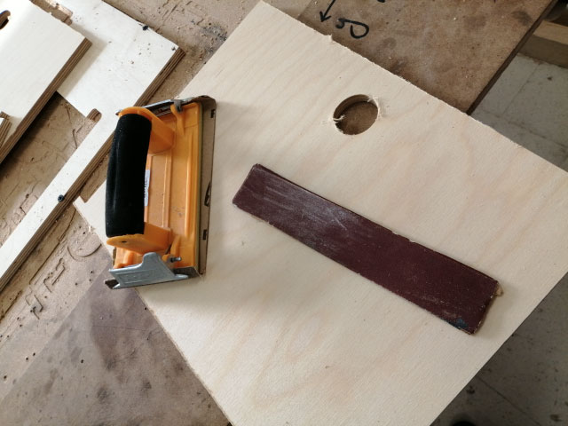
After that, I used sand paper to remove the rough surfaces on the edges of the bottom.
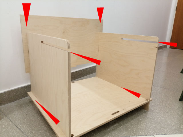
When all my parts were ready, I started assembling the unit. there was no need for a rubber hammer, it was all press fitted by hand, and it came out perfect and rigid.