Embedded programming
Assignment:
Individual assignment:
read a microcontroller data sheet, program your board to do something, with as many different programming languages and programming environments as possible.
Group assignment:
compare the performance and development workflows for other architectures.
Introduction
What is a microcontroller?
A microcontroller is a small, low-cost embedded semiconductor devices used in circuit board design.
Microcontrollers are mostly used in single-function ’embedded’ applications.
They usually have low-power requirements since many devices they control are battery-operated.
What is a microprocessor?
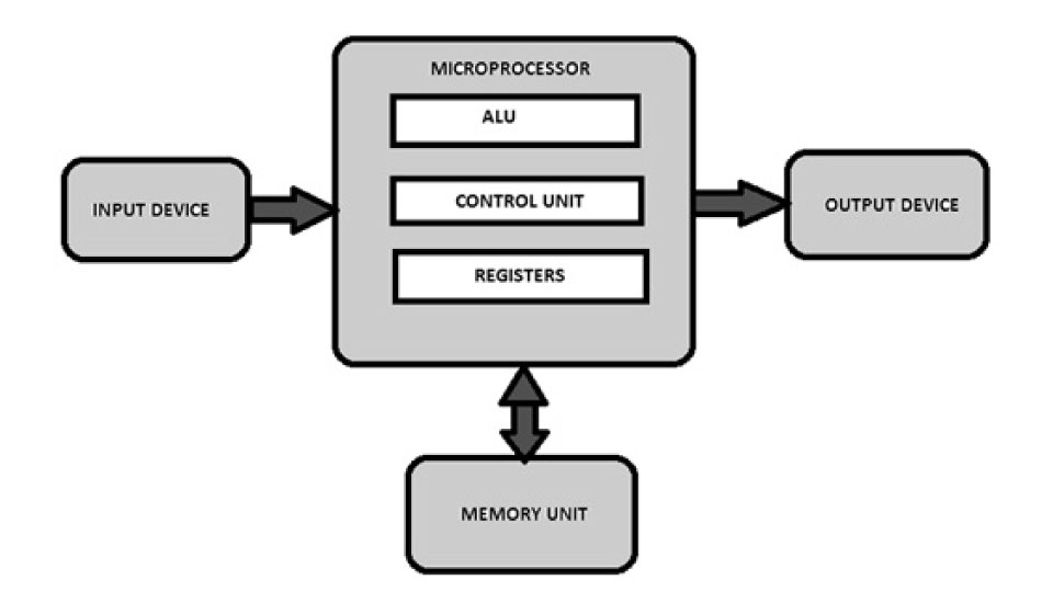
it is a miniature electronic device that contains the arithmetic, logic, and control circuitry necessary to perform the functions of a digital computer’s central processing unit. It performs arithmetic and logic operations, which generally include adding, subtracting, transferring numbers from one area to another, and comparing two numbers. A microprocessor accepts binary data as input, processes that data, and then provides output based on the instructions stored in the memory.
Difference between Microprocessors and Microcontrollers:
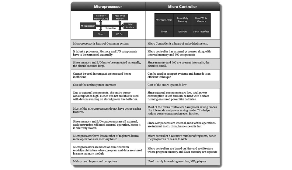
Microprocessor consists of only a Central Processing Unit, whereas Micro Controller contains a CPU, Memory, I/O all integrated into one chip. Microprocessor uses an external bus to interface to RAM, ROM, and other peripherals, on the other hand, Microcontroller uses an internal controlling bus.Microprocessor is complicated and expensive, with a large number of instructions to process but Microcontroller is inexpensive and straightforward with fewer instructions to process.
Definition of Embedded Systems
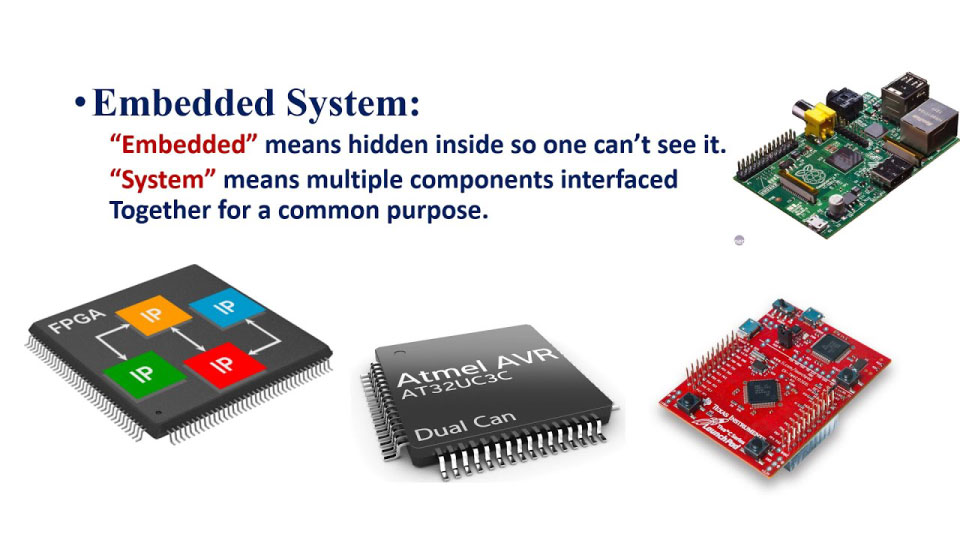
An embedded system is a microprocessor- or microcontroller-based system of hardware and software designed to perform dedicated functions within a larger systems.
AVR Microcontrollers
An AVR microcontroller is a type of device manufactured by Atmel, which has particular benefits over other common chips.
Components of a microcontroller:
Processor: The processor refers to the Central Processing Unit (CPU) of the microcontroller. It contains the Arithmetic Logic Unit (ALU), Control Unit, Instruction Decoder and some Special Registers (Stack Pointer, Status Register, Program Counter, etc.).
Volatile Memory: This is memory used by ht microcontroller for temporary data storage, system setup and peripherals configurations. Memory in this category includes SRAM and DRAM. AVR microcontrollers utilize SRAM.
Volatile Memory: This is memory used by ht microcontroller for temporary data storage, system setup and peripherals configurations. Memory in this category includes SRAM and DRAM. AVR microcontrollers utilize SRAM.
Timer Module: Most microcontrollers have at least one timer/counter peripheral. Timer/Counter modules are used to perform timing or counting operations in the controller. These include time stamping, measuring intervals, counting events, etc.
Interrupt Module: Interrupts enable the microcontroller to monitor certain events in the background while executing and application program and react to the event if necessary pausing the original program. This is all coordinated by the interrupt module.
Digital I/O Module: This module allows digital/logic communication with the microcontroller and the external world. Communication signals are that of TTL or CMOS logic.
Analog I/O Modules: These modules are use to input/output analog information from/to the external world. Analog modules include Analog Comparators and Analog-to-Digital Converters.
Serial Modules - These modules are used for serial communication with the external world. An example is the USART peripherial which utilizes the RS232 standard.
In this assignment I am going to use the Attiny44 Microcontroller.
ATTINY44 AVR MICROCONTROLLER
From the datasheet we can see that it is ATtiny44 is a low-power CMOS 8-bit microcontrollers based on the AVR enhanced RISC architecture.
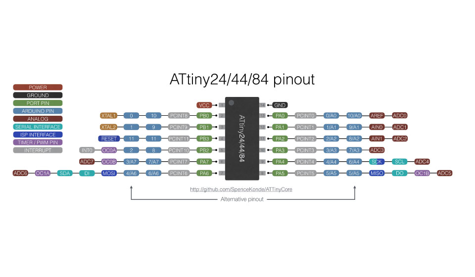
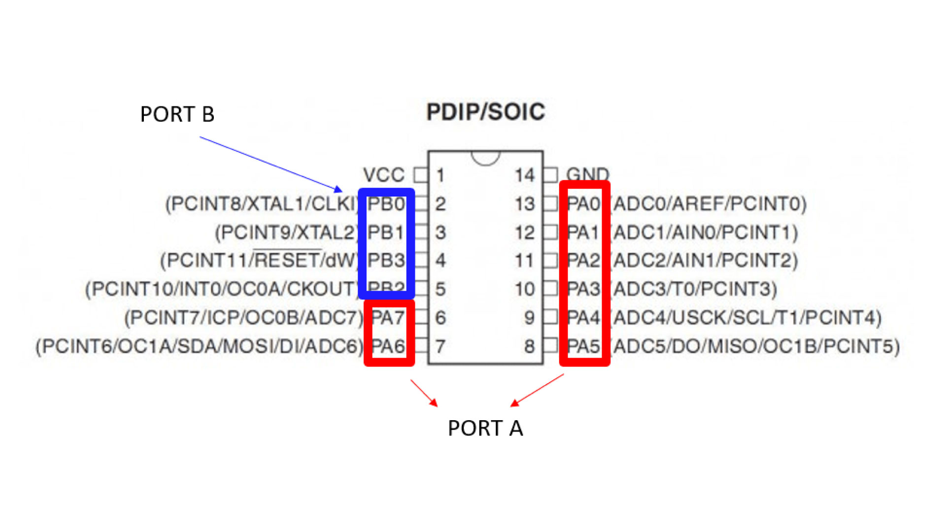
Pinout:
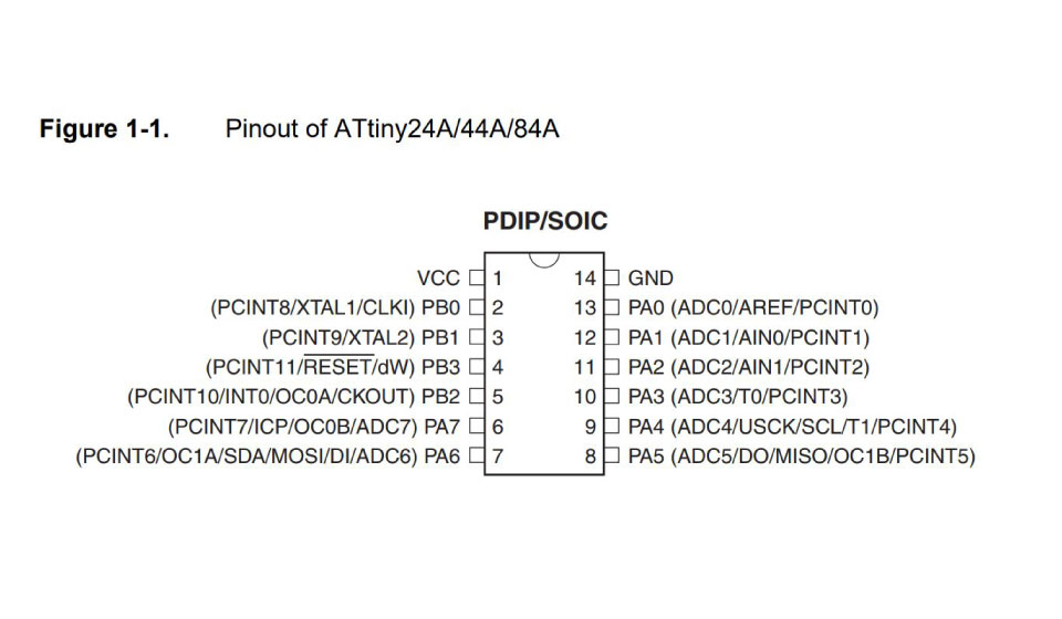
Pin discreption:
VCC: Supply voltage
GND: Ground
Port B (PB3...PB0): Port B is a 4-bit bi-directional I/O port with internal pull-up resistors (selected for each bit). As inputs, Port B pins that are externally pulled low will source current if the pull-up resistors are activated.so we don't need to add a pull-up resistor externally for button's and other purpose.
RESET: Reset input. A low level on this pin for longer than the minimum pulse length will generate a reset, even if the clock is not running.a reset will just reset the program that currently running .
Port A (PA7...PA0): Port A is a 8-bit bi-directional I/O port with internal pull-up resistors (selected for each bit). As inputs, Port A pins that are externally pulled low will source current if the pull-up resistors are activated
My Hello world board
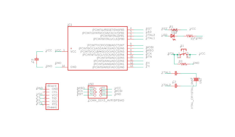
As we can notice, Pin5 = PB2 is used as an output, a red LED is connected to it
Pin10 = PA3 is used as an input and a Button is connected to it
Programming the Hello world board using the ISP
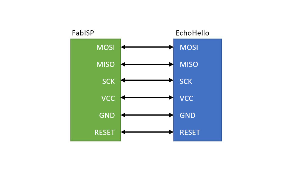
We can program AVR microcontroller using an ISP, serial peripheral interface connnecctions like MISO, MOSI and clock (SCK) are connected to allow the chip to be programmed.
The SCK pin is where the Master provides the clock information for communication
Every clock cycle sends one bit of data over both the MOSI and MISO pins
The RESET pin is the channel to which the ISP is able to erase the contents on the AVR chip and enable serial programming
Make sure to connect the ISP to the PC using a USB connector, not directly to the USB port, double chek the connections between the ISP and the board, and then Upload the code.
We need to burn bootloader as the first step before we can upload any code to the microcontroller, this step has been done in week six.
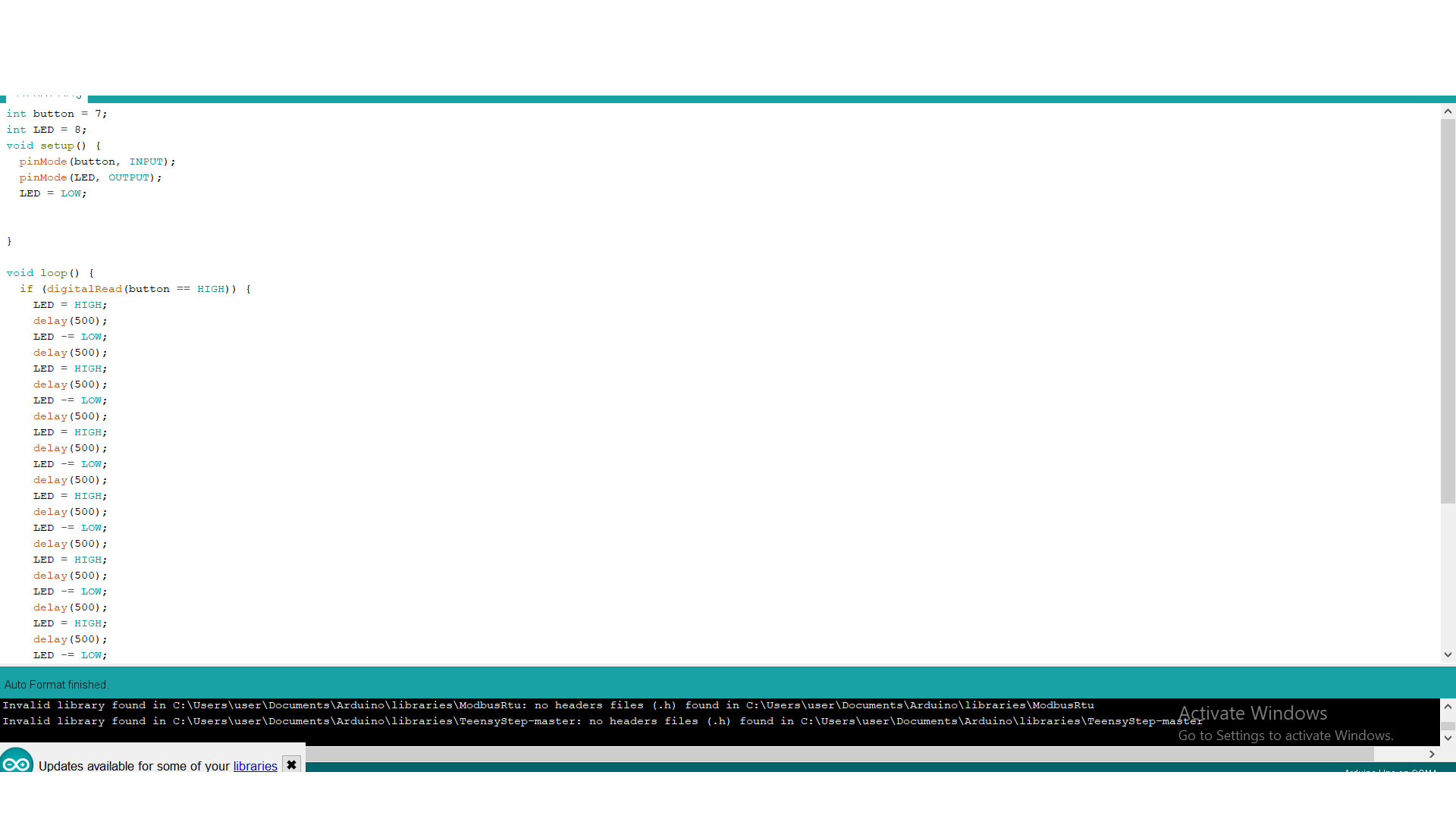
Programming using Arduino IDE:
I wanted to used the ISP that I produced in week four. to program my board. However, due to llock down, the board was in the Lab and I had to use Arduino instead. first i connected them follwing ISP connections. and then i chose my board preferences, and uploaded the code.
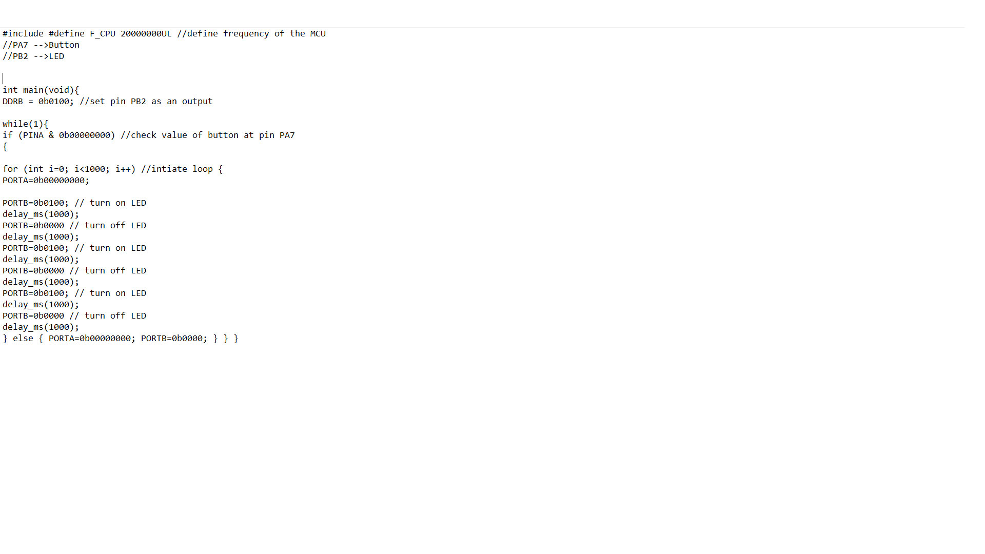
Programming using C language:
We must understand that the AVR I/O pins are associated with a data direction register, a pin register, and port register.
the ATtiny44 has two sets of ports.
We can set which port is input and which will be used as an output.
In order to upload the code, I had to prepare the make file, that is used to compile the code before uploading to the microcontroller..
Below is the C code that will keep blinking the LED until button is pressed.
To upload my code, using UBUNTU operating system, with the ISP as the programmer. First, I had to install the AVR Libraries
sudo apt-get install flex byacc bison gcc libusb-dev avrdude
sudo apt-get install gcc-avr
sudo apt-get install avr-libc
sudo apt-get install libc6-dev
make blinking.hex
make blink.out
make program-usbtiny
