15. Interface & App Programming
Week assignment
- We have to compare as many tool options as possible (in group)
- I have to write an application that interfaces a user with an input or output device that I’ve made (individually)
Comparing Tool Options
I wanted to compare different types of interfaces. So, I picked Scratch, which uses a no-code UI, Processing, which is similar to Arduino IDE but focused on electronic arts, new media art, and visual design, and then I used Unity 3D and Arduino IDE for my individual assignment.
Scratch
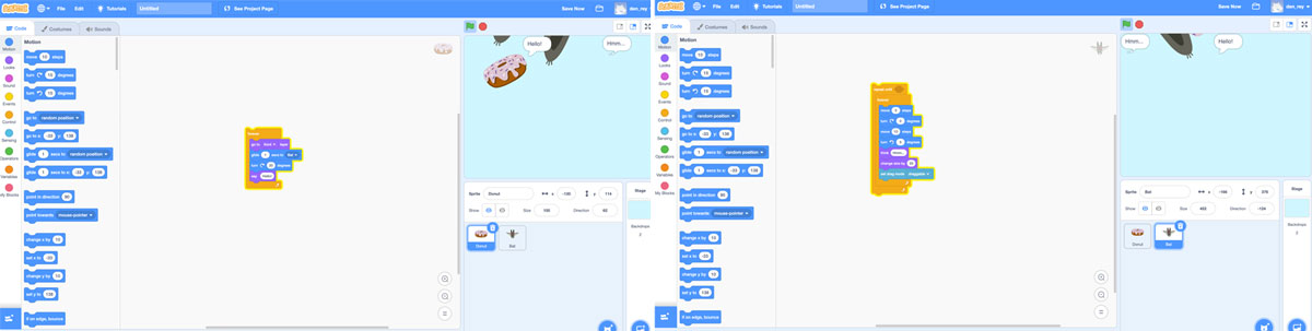
Scratch is by far the easiest tool to use. It uses a block-based visual programming language and is aimed at kids. You just need to pick a character and then drag and drop blocks to animate it. I chose to animate a bat by creating a loop. The bat moved, rotated, changed its size, and displayed a thinking bubble. I also added a background and found that you can customize your character and add sounds. There are multiple tutorials, and it seems you can achieve quite complex things.
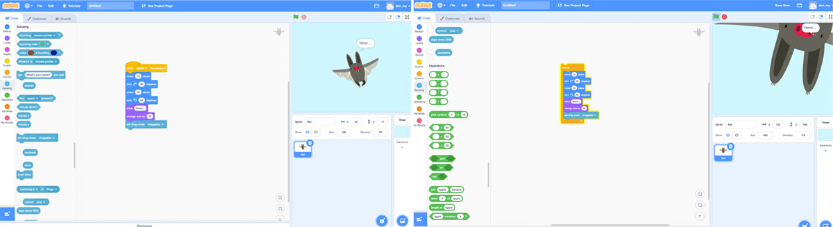
When I finished my first sketch, I added a donut and made it follow the bat while rotating and displaying a text bubble. Overall, I found this platform enjoyable and simple to use.
Processing
Processing is quite a friendly tool too, although not as friendly as Scratch. They define the tool as “a flexible software sketchbook and a language for learning how to code within the context of the visual arts.” So, as I wanted to experiment, I decided to make a simple animated 2D shape. I created this character: Dynamic Bob and wrote the following code. Bob follows your mouse cursor while printing “Hi! I’m Bob and I will follow you forever :)”
To accomplish this, I followed some of the basic tutorials available on their website. I found it easy and intuitive, probably because I already have some experience using Arduino IDE. However, I felt that Processing is easier as its logic is similar to the way I think. When using Arduino, I have to learn how things work or look for examples every time I need to create something new.
void setup() {
  size(250,250);

}

void draw() {
  background(250);
// Bob's body
noStroke();
fill(0);
ellipseMode(CENTER);
ellipse(mouseX,mouseY,110,100);

// Bob's head
ellipse(mouseX,mouseY-70,70,70);
fill(255);
ellipse(mouseX-10,mouseY-70,5,5);
ellipse(mouseX+10,mouseY-70,5,5);
stroke(255);
strokeWeight(4);
line(mouseX-10,mouseY-60,mouseX+10,mouseY-60);

// Bob's hands
fill(0);
noStroke();
rect(mouseX-60,mouseY-30,20,20,30);
rect(mouseX+40,mouseY-30,20,20,30);

// Bob's legs
rect(mouseX-25,mouseY+40,15,25,10);
rect(mouseX+10,mouseY+40,15,25,10);

// BoB Talking

println("Hi! I'm Bob and I will follow you forever :)");

}
void setup() {
  size(250,250);
  background(250);
}

void draw() {

// Bob's body
noStroke();
fill(0);
ellipseMode(CENTER);
ellipse(mouseX,mouseY,110,100);

// Bob's head
ellipse(mouseX,mouseY-70,70,70);
fill(255);
ellipse(mouseX-10,mouseY-70,5,5);
ellipse(mouseX+10,mouseY-70,5,5);
stroke(255);
strokeWeight(4);
line(mouseX-10,mouseY-60,mouseX+10,mouseY-60);

// Bob's hands
fill(0);
noStroke();
rect(mouseX-60,mouseY-30,20,20,30);
rect(mouseX+40,mouseY-30,20,20,30);

// Bob's legs
rect(mouseX-25,mouseY+40,15,25,10);
rect(mouseX+10,mouseY+40,15,25,10);

// BoB Talking

println("Hi! I'm Bob and I will fill you forever :)");

}
Interface & App Programming
Week assignment
- We have to compare as many tool options as possible (in group)
- I have to write an application that interfaces a user with an input or output device that I’ve made (individually)
Comparing Tool Options
I wanted to compare different types of interfaces. So, I picked Scratch, which uses a no-code UI, Processing, which is similar to Arduino IDE but focused on electronic arts, new media art, and visual design, and then I used Unity 3D and Arduino IDE for my individual assignment.
Scratch
Scratch is by far the easiest tool to use. It uses a block-based visual programming language and is aimed at kids. You just need to pick a character and then drag and drop blocks to animate it. I chose to animate a bat by creating a loop. The bat moved, rotated, changed its size, and displayed a thinking bubble. I also added a background and found that you can customize your character and add sounds. There are multiple tutorials, and it seems you can achieve quite complex things.
When I finished my first sketch, I added a donut and made it follow the bat while rotating and displaying a text bubble. Overall, I found this platform enjoyable and simple to use.
Processing
Processing is quite a friendly tool too, although not as friendly as Scratch. They define the tool as “a flexible software sketchbook and a language for learning how to code within the context of the visual arts.” So, as I wanted to experiment, I decided to make a simple animated 2D shape. I created this character: Dynamic Bob and wrote the following code. Bob follows your mouse cursor while printing “Hi! I’m Bob and I will follow you forever :)”
To accomplish this, I followed some of the basic tutorials available on their website. I found it easy and intuitive, probably because I already have some experience using Arduino IDE. However, I felt that Processing is easier as its logic is similar to the way I think. When using Arduino, I have to learn how things work or look for examples every time I need to create something new.
Observations with Dynamic Bob
I noticed that when the animations were running simultaneously, they printed a line with ‘fill’ and the next one with ‘follow’.
Unity 3D for Final Project
I used Unity 3D to develop the interface for my final project. It is a tool that mixes code and a no-code interface. While the platform’s UI is confusing, once you get used to it, it’s relatively straightforward. However, doing advanced things can be very complex, at least for someone with basic knowledge like me.
This platform allows you to combine scripts written in C# with a UI from where you can also modify variables defined in the code.
In the next section of this assignment, I explain how I made the graphic interface for the OLED using Arduino IDE and how I developed the first part of the game for my final project using Unity 3D.
Interface Programming
For this week, I wanted to continue with the progress on my final project. My project has 2 interactive interfaces. The first involves a pedometer, which I have not yet programmed, and that when walking changes the faces on an OLED. The second is a 2D game made in Unity 3D that can be controlled using the gyroscope of the MPU6050 module on my board.
I decided to start with the game since I still have not solved the pedometer.
Using Bluetooth BLE and the Gyro
My board has an ATtiny3216, an MPU6050, a 128x64 I2C OLED, and a Bluetooth BLE HC-10. I knew there was a library for HC-10 in Unity, so I decided to acquire it to make my life easier. The other decision I made was to download a demo of a game since the time is very short, and I will not be able to develop something decent from scratch. My idea is to use something pre-existing and create my custom sprites.
I had the code for the gyroscope I used for the OLED output week. Therefore, the first change I made was to modify the code so that in addition to sending the X, it sends the Y on the Arduino. I used the same code but didn’t connect the OLED. It didn’t work. Later, I realized that if the OLED is not connected, the code does not work. For this assignment, I just wanted to try the Bluetooth and gyro with Unity 3D. So, I removed all the parts related to the OLED.
This is the code that I used:
#include <Wire.h>
#include <MPU6050_light.h>
MPU6050 mpu(Wire);

#include <SoftwareSerial.h>

SoftwareSerial bluetooth(6, 7); // RX, TX


void setup() {
 // set the data rate for the SoftwareSerial port
  bluetooth.begin(9600);

  Serial.begin(9600);
   Wire.begin();
 byte status = mpu.begin();
   Serial.print(F("MPU6050 status: "));
   Serial.println(status);
   while (status != 0) { } // stop everything if could not connect to MPU6050
 Serial.println(F("Calculating offsets, do not move MPU6050"));
   delay(1000);
   mpu.calcOffsets(); // gyro and accelero
   Serial.println("Done!\n");
}

void loop() {

  mpu.update();


  delay(50);
  float angley = mpu.getAngleY(); // declare the angle Y of the gyro on the variable angle
  float anglex = mpu.getAngleX(); // declare the angle X of the gyro on the variable angle

  Serial.print(angley);
  Serial.print(":");
  Serial.println(anglex);

}
Interfacing the Board with Unity 3D
- First, I created a new project in Unity.
- Then, I imported the game that I downloaded.
- Finally, I imported the library for HC-10.
How to Get Bluetooth to Work
Initially, I used the example Bluetooth BLE file to understand how it worked. It did not work at first 0_0
Therefore, I had to modify it minimally to scan the device. I changed the device name in the script and in the Unity editor. The name of the device is “BT05”. I already knew the name from the iOS app.
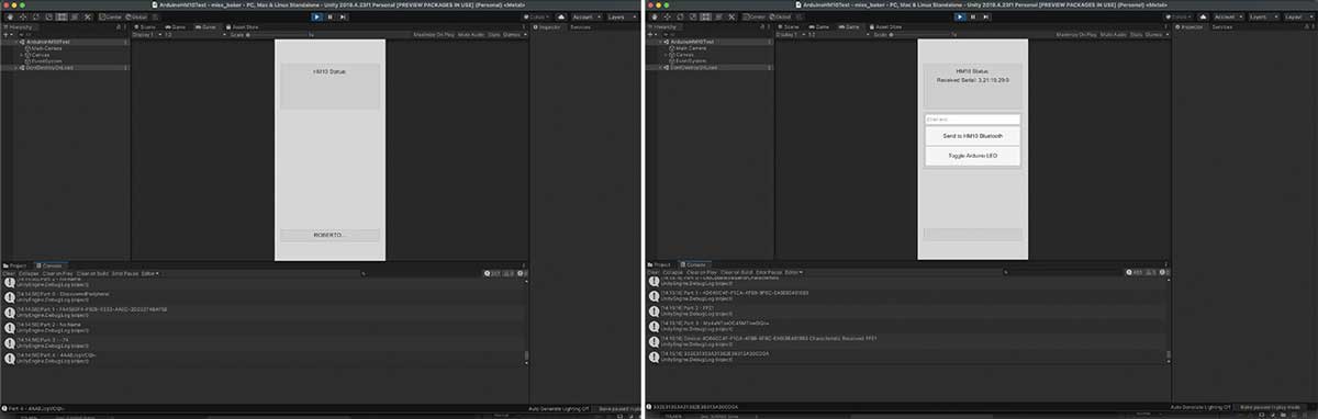
I changed the name of the button to Roberto because I didn’t understand if my changes were saved. Then, it started showing data on the console. It was easy to make it work but a little tricky to understand.
Getting the Bluetooth into the Game
Once I managed to connect the Bluetooth to Unity, I moved on to the next stage. I did the following steps:
- Copied the file from the example BTLE and moved it to the game project. Just the script
PlayerBluetoothConnect. - Made changes to the script to save and calculate what the Bluetooth sends.
- Added the Bluetooth name.
- Renamed the public class so that it did not collide with the previous one.
public class PlayerBluetoothConnect : MonoBehaviour
{
    public string DeviceName = "BT05";
    public string ServiceUUID = "FFE0";
    public string Characteristic = "FFE1";

    public static float AngleY { get; set; } //define angle Y and make it public so the game can access and use the value
    public static float AngleX { get; set; } //define angle X and make it public so the game can access and use the value
Then I had to:
- Change the values of variables X and Y
- Use gyroscope values
string data = Encoding.UTF8.GetString (bytes); //getting the bluetooth data and turning it into text to be able to process it (data = y : x)

                    string[] values = data.Split(':'); //values to recieve and tranform into an array (split the x and the y into separate values --> values = ["10.0","20.0"])
                    AngleY = float.Parse (values[0]); // variable Y: transform the text for Y into a number
                    AngleX = float.Parse (values[1]); //Variable X: transform the text for X into a number
                    });
Last but Not Least
-
Add the Script to Main Camera: I added the script to the main camera so that it initializes when the game starts.
-
Modify
playerMoving.cs: I changedplayerMoving.csto use the Bluetooth’s X and Y values to move the player. The script now updates the player’s position based on the X and Y values from the Bluetooth. The modified line of code is:
transform.position = Vector3.MoveTowards(transform.position, new Vector3(transform.position.x + PlayerBluetoothConnect.AngleX,transform.position.x + PlayerBluetoothConnect.AngleY), 30 * Time.deltaTime);
- Disable the Collider: I disabled the collider so the ship doesn’t get destroyed while it’s searching for the Bluetooth connection. (To be improved)
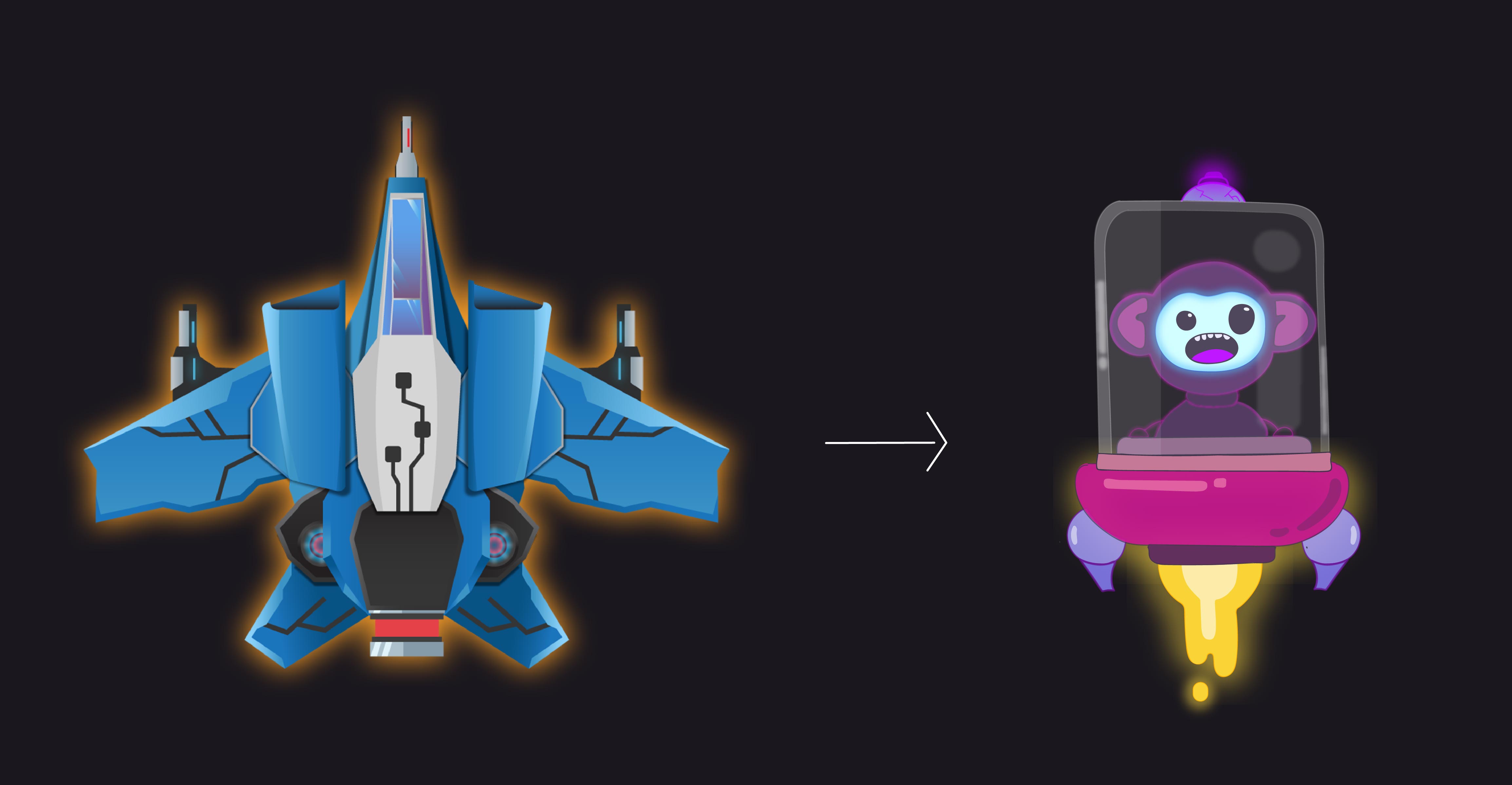
I experimented with some ideas for the game by making changes to the assets in the template I was using. These are not the final assets, but they helped me gauge the time required to create and update all sprites.
Printing Faces on the OLED
This was the hardest part of the week, probably because I expected it to be easier. Drawing two basic faces on the OLED can be challenging, especially with the limited memory of the Attiny. Although I upgraded my board from the 1614 to the 3216, which is a 100% memory increase, it was still not enough to use the Adafruit Libraries directly. I had to find workarounds.
Two of the most helpful resources I discovered this week were: 1. Wokwi Arduino Simulator - This website allowed me to test my code without dealing with physical wiring, and it was also great for collaboration. 2. Image2CPP Converter - This tool helped me convert bitmap images into code.
I created two PNG files for sad and happy faces:

To understand how to use bitmaps with the OLED and Attiny, I used this tutorial and Tiny4kOLED examples. I had some issues initially due to using the wrong image size, which was a bit confusing.
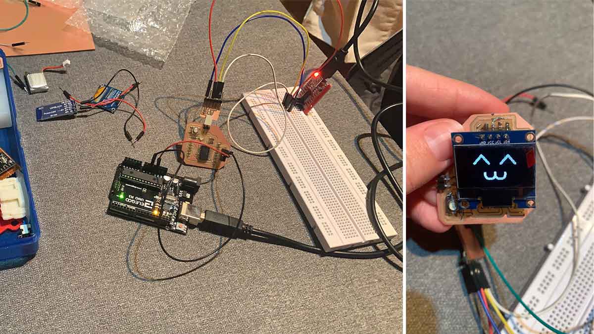
After several hours, I managed to alternate between the sad and happy faces with a 1000ms delay.
So, for the OLED, I used the following code:
#include <Tiny4kOLED.h>
#include "SolomonSystech.h"

void setup() {

oled.begin(128, 64, sizeof(tiny4koled_init_128x64r), tiny4koled_init_128x64r);

  // To save space, the bitmap is cropped left and right,
  // intended to be drawn onto a clear screen
  oled.clear();

  // Now that the display is all setup, turn on the display
  oled.on();

  Serial.begin(9600);
   Wire.begin();

}

void loop() {

  oled.bitmap(0, 0, 128 , 8, sadface_bitmap);
  delay (1000);

  oled.bitmap(0, 0, 128 , 8, happyface_bitmap);
  delay (1000);

}
<
This was just the first part. Next, I needed to figure out how the pedometer works. The goal was to show a sad face if the accelerometer is not changing and a happy face if it is. I started by researching how a pedometer works.
How the Pedometer Works
Note
A pedometer calculates the total number of steps taken by a person using three components of motion: forward, vertical, and side-to-side. The pedometer system uses an accelerometer to gather these values. The accelerometer continuously updates the maximum and minimum values of these 3-axis accelerations after a defined number of samples. The average of these 3-axis values, (Max + Min)/2, is called the dynamic threshold level. This threshold value is used to determine whether a step has been taken.
An approach to how the code should work:
- The pedometer starts calibration as soon as it gets powered.
- In the
void loopfunction, it continuously retrieves data from the X, Y, and Z axes. - It calculates the total acceleration vector from the starting point.
- The acceleration vector is the square root of (x^2 + y^2 + z^2) of the X, Y, and Z axis values.
- It compares the average acceleration values with the threshold values to count the steps.
- If the acceleration vector crosses the threshold value, the step count increases; otherwise, invalid vibrations are discarded.
So, I followed this tutorial:
I used the code from the comments of that video and removed all parts related to the OLED.
#include <MPU6050_tockn.h>
#include <Wire.h>

MPU6050 mpu6050(Wire);
long timer = 0;
int steps=0;
  float distanceinonestep=71; //change it according to your distance between your legs in cm
  float distance;

void setup() {
  Serial.begin(9600);

Wire.begin();
  mpu6050.begin();
  mpu6050.calcGyroOffsets(true);
}

void loop() {
  mpu6050.update();

  if(millis() - timer > 1000){


    Serial.print("\taccY : ");Serial.println(mpu6050.getAccY());
  }
if(mpu6050.getAccY()>1)
{
  steps+=1;
  delay(350);
}
   distance = steps*distanceinonestep/100;
    Serial.println(distance);
}
How to Change the OLED Faces Using the Pedometer
Finally, I was able to merge both codes and decided to include the one I was using for the gyroscope with the Bluetooth. I did this to ensure everything was working correctly with the Attiny3216.
This was the final code I used:
//accelerometer and gyro libraries
#include <Wire.h>
#include <MPU6050_tockn.h>
MPU6050 mpu(Wire);

//bluethooth
#include <SoftwareSerial.h>
SoftwareSerial bluetooth(6, 7); // RX, TX

//OLED and faces
#include <Tiny4kOLED.h>
#include "SolomonSystech.h"

//pedometer
float vectorprevious; //previous movement
float vector; //current movement
float totalvector; //difference between vector and previous vector
int steps = 0; //steps
int prevSteps = 0; //saves previous steps

void setup() {

// set the data rate for the SoftwareSerial port
  bluetooth.begin(9600);

// put your setup code here, to run once:
oled.begin(128, 64, sizeof(tiny4koled_init_128x64r), tiny4koled_init_128x64r);

  // To save space, the bitmap is cropped left and right,
  // intended to be drawn onto a clear screen
  oled.clear();

  // Now that the display is all setup, turn on the display
  oled.on();

   Serial.begin(9600);
   Wire.begin();
   mpu.begin();

   Serial.println(F("Calculating offsets, do not move MPU6050"));
   delay(1000);
   mpu.calcGyroOffsets(true); // gyro and accelero
   Serial.println("Done!\n");
}

void loop() {
mpu.update();

  delay(50);
  float angley = mpu.getAngleY(); // declare the angle Y of the gyro on the variable angle
  float anglex = mpu.getAngleX(); // declare the angle X of the gyro on the variable angle

  calculatesteps(); //calls the acction defined as calculatesteps

  Serial.print(angley);
  Serial.print(":");
  Serial.print(anglex);
  Serial.print(":");
  Serial.println(steps);//sending the amount of steps

  //If the user walks then change the face
  if (steps - prevSteps > 0) {
    oled.bitmap(0, 0, 128 , 8, happyface_bitmap); //happy face
  } else {
    oled.bitmap(0, 0, 128 , 8, sadface_bitmap); //sad face
  }

  prevSteps = steps;
  delay(500);

}

void calculatesteps(){

  float accelX = mpu.getAccX();
  float accelY =   mpu.getAccY();
  float accelZ =   mpu.getAccZ();
  Serial.print(accelX);
  Serial.print(",");
  Serial.print(accelY);
  Serial.print(",");
  Serial.println(accelZ);

  vector = sqrt( (accelX * accelX) + (accelY * accelY) + (accelZ * accelZ) ); //Calculates a uniform acceleration vector
  totalvector = vector - vectorprevious; //Difference between vectors

  if (accelY > 1){
    steps++;
  }
// Uses the value 6 to define the difference between 2 moments and understand if there was a 'step'

  vectorprevious = vector; //saves the last value to be able to compare it with the next value
}
Find the final files here:
- gyro Y X + bluetooth
- Unity game bluetooth script
- Unity game player movement script
- Sad and Happy faces code
- Sad and Happy bitmap
- faces + pedometer
- faces.h
- Bob dynamic
- Bob full