5. Electronics Production
Week assignment
- Characterize the design rules for my PCB production process: document feeds, speeds, plunge rate, depth of cut (traces and outline) and tooling.
- Document my work (in a group or individually)
- Make an in-circuit programmer by milling and stuffing the PCB, test it, then optionally try other PCB fabrication process (individually)
Characterize the design rules for my PCB production process.
Some important data:
- It is not the same stroke and outlines:
- The line is made with the finest end-mill, 1/64 and at a speed of 3 mm/s
- The exterior (which is called interior) is done with the 1/32 end-mill at a speed of 1.5 mm/s and the height will be equal to the thickness of the material you are cutting.
- Never change the size if so, trace and outline won’t match.
- You never have to change the XY origin when going from stroke to outline.
- Remember to correctly set the origin in Z and raise the header later.
- Export files in .PNG in about 1000dpi
- Log should be always greater than 0 (60,5 is the default but 20 is enough).
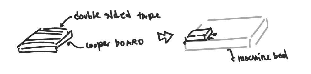
- Stick the copper to the bed with double-side tape and press a little bit. Check that the surface is even.
- Do not overtouch the copper with your hands.
We divided into groups and tried the SRM-20 and the portable milling machine. These machines have different paths to create the files.
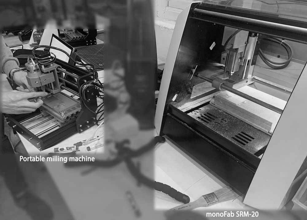
My experience with the Roland SRM-20
Some data about the machine: 1. Work area: 203.2 x 152.4 x 60.5mm 1. Loadable workpiece weight: 2kg 1. Operating speed: 6mm/min - 1,800mm/min 1. Spindle speed: 3,000 – 7,000rpm 1. Input Format: RML-1 1. Material: Modeling Wax, Chemical Wood, Foam, Acrylic, PCB
While I started testing, I put together a checklist because I was stressed by the ease with which the end-mill could break.
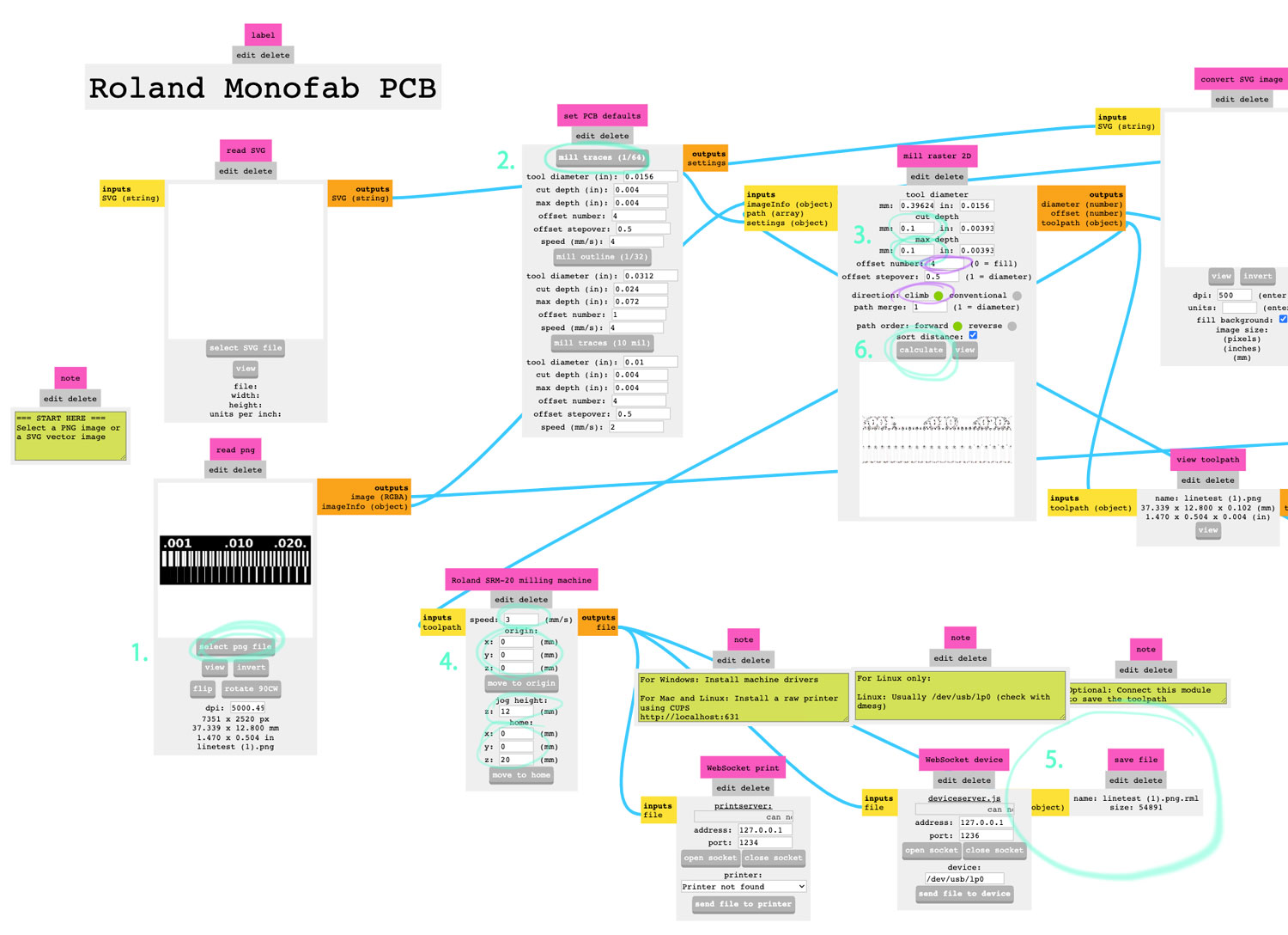
SRM-20 checklist
- Download .png
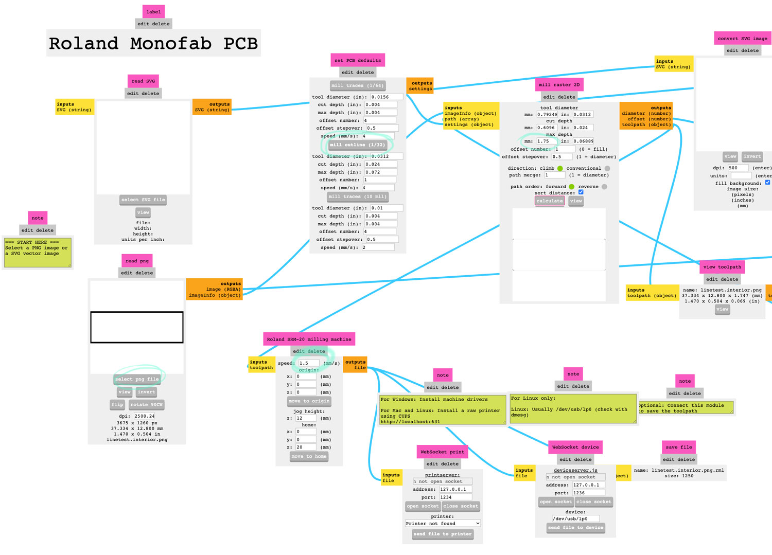
- Open Mods
- Right click > open project > select machine SRM-20
- Upload .png [Read png]
- Select the end-mill [set PCB default]
- Edit cut depth, max depth accordingly. Optionals offset number and direction [mill raster]
- Edit the speed accordingly. Origin should be (0,0,0), jog height: 12, home: (0,0,20) [Roland SRM-20 milling machine]
- Connect [Roland SRM-20 milling machine] with [save file]
- Go back to [mill raster] and press calculate. It will automatically download the file.
- Repeat for traces/interior modifying the parameters.
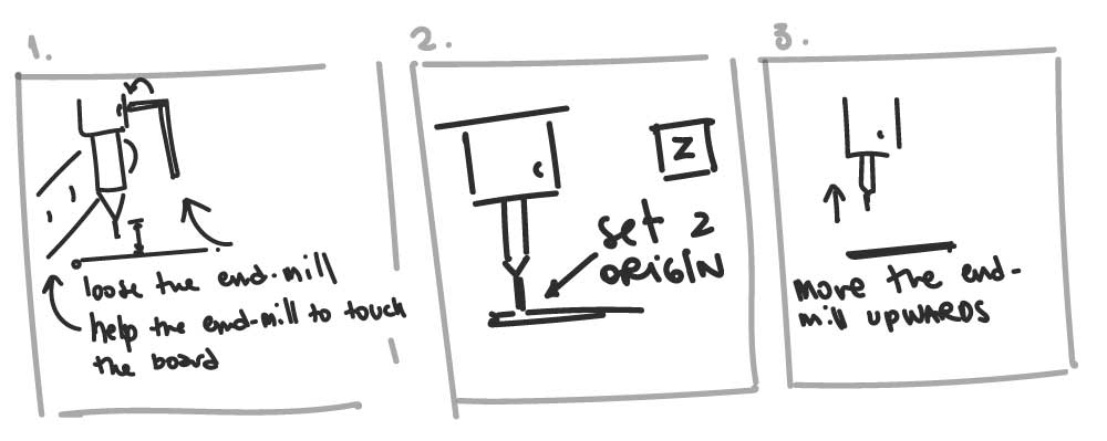
Special notes on Z origin
Note
• The origin in Z is set separate from XY. • To do this you have to place the end-mill and slowly bring the tool closer to the plate (there’s an option to change the speed to avoid smashing it). • Then gently brake and unscrew the head. Accompany the end-mill until it touches the copper plate. • Screw the head back on. Touch the Z Origin button. • Raise the head again.
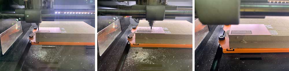
Preparing the traces
Preparing the interior
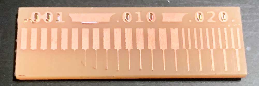
Testing
- Material: Double Sided Copper Clad
- Size:
- Bed size:
| Milled part | Speed | Depth of cut | Tooling | Direction |
|---|---|---|---|---|
| Traces | 3 | 0.1016 mm | 1/64 | Climb |
| Interior | 1.5 | 1.75 mm | 1/32 | Climb |
Document my work
I decided to cut the PCB using the SRM-20. So, I created my files following the process on Mods. Then, I uploaded them to the cloud and from there to the computer. Everything seemed to be fine, except for some details that I thought I was going to be able to fix by hand.
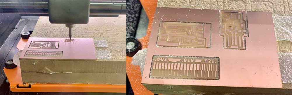
But no, some of the traces that connected to the microcontroller had come off. So, I had to cut it again. It took me 5 pieces to get to something decent enough.
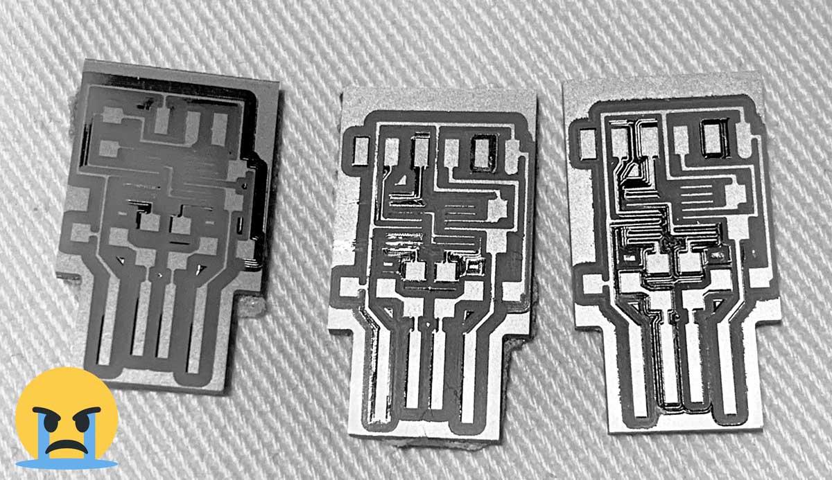
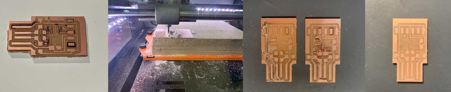
I emphasize teamwork and group support in the process of cutting a piece that is suitable for soldering. The milling machine created the lines well once, then it did them wrong and ok randomly, using the same parameters. The process seemed extremely random and very difficult to control. After all, I feel like it was more based on trial and error. It was really frustrating.
Tools I used to mill my boards
At the Fab Lab the instructors gave us 2 end-mills:
- A 1/64 2-flute that I always used for traces.
- A 1/32 2-flute that I always used for the interior.
Make an in-circuit programmer
One of the most complex things was finding the components. Thanks to the group’s help, we were able to figure out where each component was and “create” the missing connectors by bending the legs to standard ones.
Probably, my first mistake was choosing to use the solder kit we got. I don’t have much experience with soldering, and the times I did it, I did it with machines that could regulate properly and using much larger components. The biggest problem was the temperature regulation. There is a tremendous difference between the things I solder in the Lab with the ones I did at home. Also, the thickness of the tin in the Lab was much thinner than what I initially used.
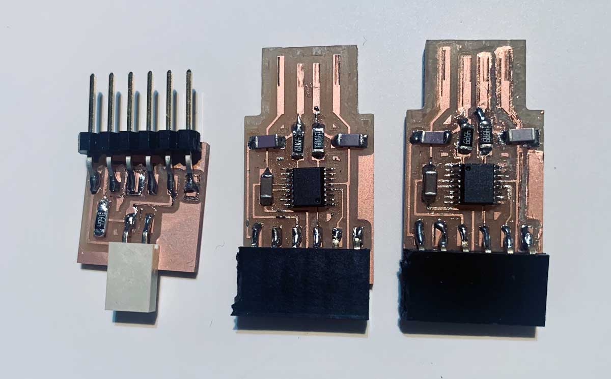
Soldering Process
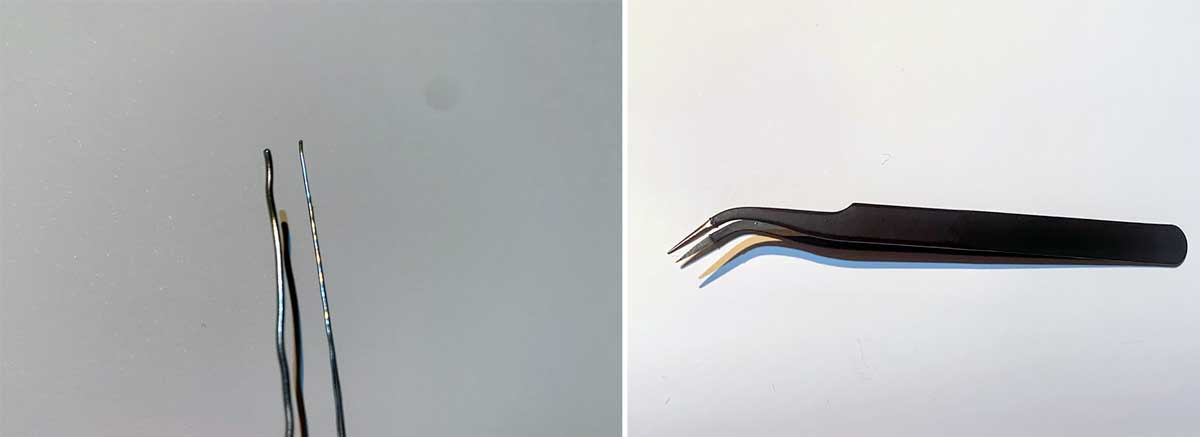
For soldering, I initially used 1mm tin wire, but switched to a thinner wire as it allowed for more precise application. The most useful tool was the soldering tweezers with a curved end.
Initially, I used FLUX paste to facilitate the soldering process. However, it was pointed out that FLUX paste is highly toxic, so I switched to using copper wire for assistance.

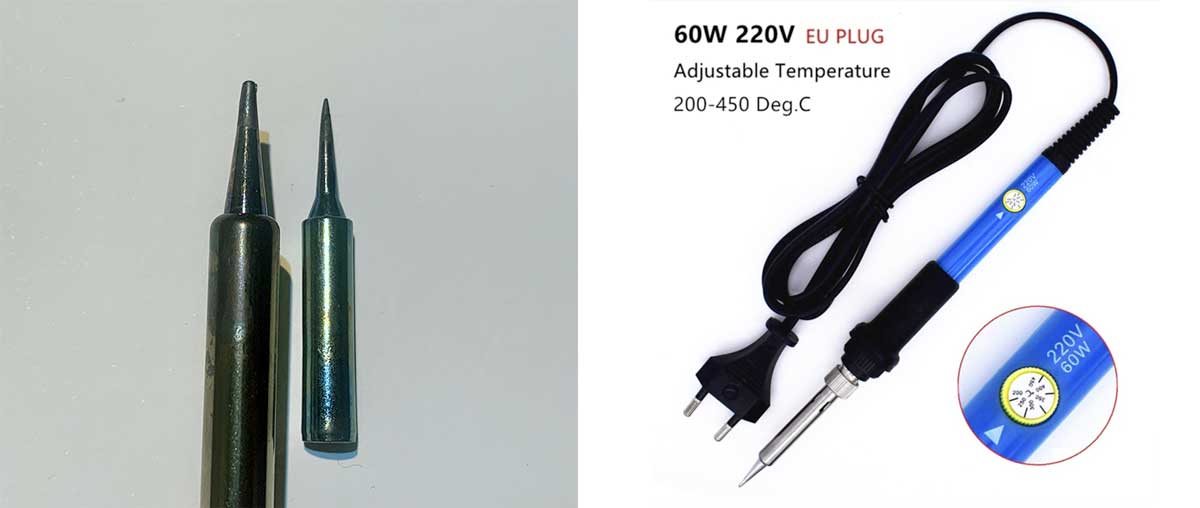
I used a standard soldering machine provided by the lab for home use. I initially used a finer tip, but the inconsistent heat led me to switch back to a thicker tip for better results.
Boards Created Using the Kit Soldering Machine
At Home
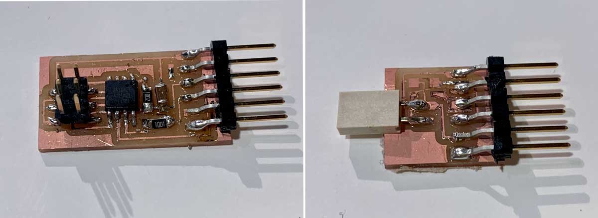
At the Lab
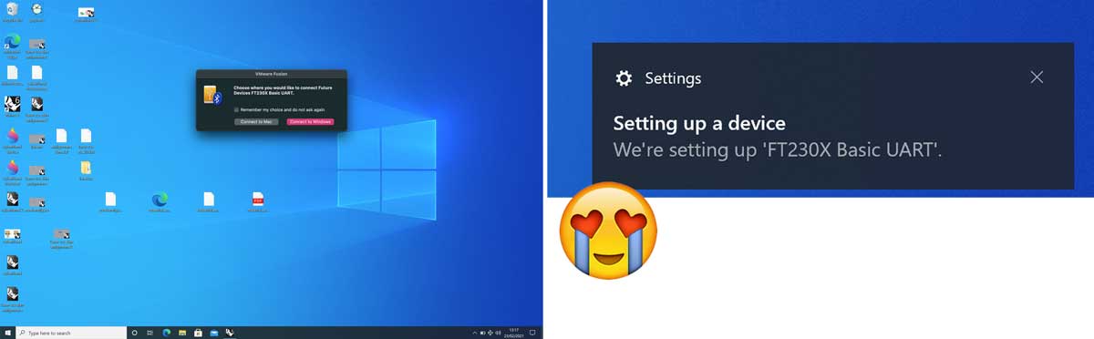
Final Pieces
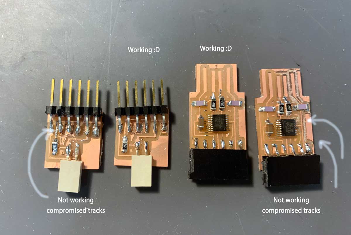
After multiple attempts, I successfully created a piece that was recognized as a device by the computer.
Although I intended to use the vinyl cutter to create a flex circuit from a copper sheet, the challenges I faced with the in-circuit programmer left me with insufficient time to pursue this.
Files Cut
- Linetest: Traces | Interior
- Serial UPDI: Traces | Interior
- ATtiny45: Traces | Interior
- USB-FT230XS: Traces | Interior