14. Communications
Week assignment
- Sending a message between two projects (in group)
- Designing, building, and connecting wired or wireless node(s) with network or bus addresses (individually)
How will my modules communicate with another device?
I wanted to use this week to understand how the components of my board will communicate with each other and with the game on another device.
I’ll need only one board with the MPU6050, the OLED, and an HC-10 module for communication.
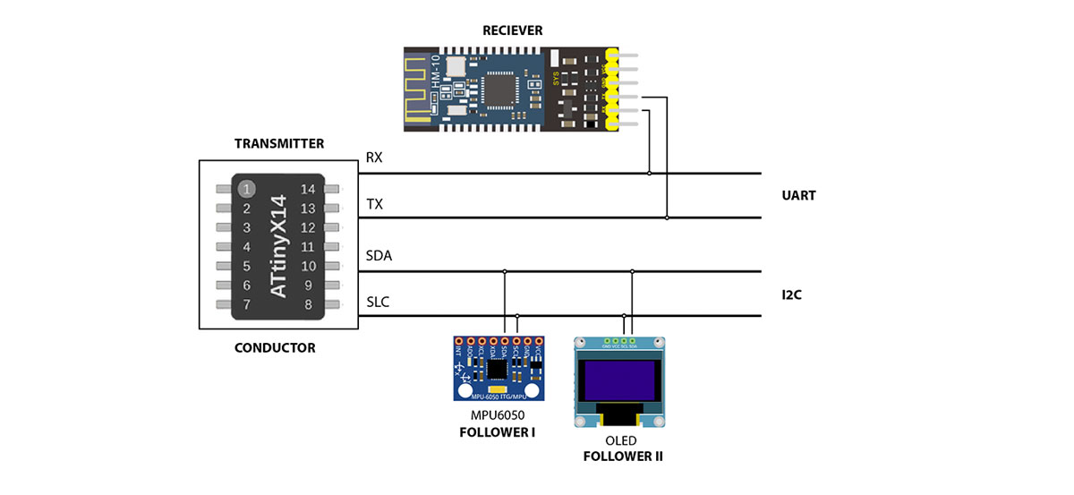
What’s UART?
UART stands for Universal Asynchronous Receiver/Transmitter. It’s designed to transmit and receive serial data. UART communication uses only two wires: one for transmitting data and one for receiving data. Unlike I2C, UART is not a communication protocol but a physical circuit within a microcontroller.
In UART communication, there is a Transmitting UART and a Receiving UART. The Transmitting UART sends data to the Receiving UART. This data is organized into packets, and the Receiving UART can detect if any data has changed during transmission. A notable disadvantage of UART is that it only supports communication between two devices at a time.
What’s I2C?
I2C (Inter-Integrated Circuit) is a serial communication protocol where data is transferred bit by bit along a single wire (the SDA line). I2C allows multiple devices to communicate on the same bus using only two wires:
- SDA (Serial Data Line): This line is used for sending and receiving data between the master and slave devices.
- SCL (Serial Clock Line): This line carries the clock signal to synchronize data transfers.
Each device on the I2C bus has a unique address, allowing the master to select which device it communicates with.
Designing, building, and connecting wired or wireless node(s) with network or bus addresses
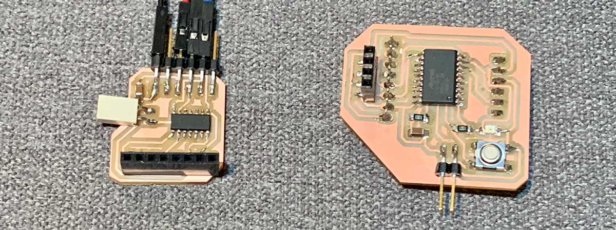
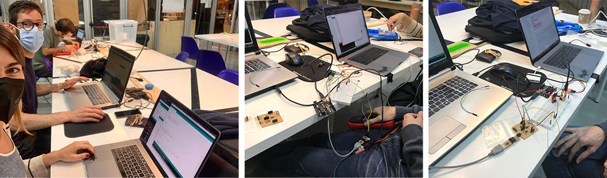
For this week’s assignment, I needed to design, build, and connect nodes. One potential solution to my memory issues was to use two microcontrollers connected via TX/RX. Although I had already designed a new board with an ATtiny3216, I wanted to experiment with this approach.
I used my first ATtiny1614 and my new ATtiny3216 to test I2C communication. I connected the SDA and SCL lines between the boards. My goal was to send a simple message from one controller to the other, instructing it to blink an LED.
Code for the Controller:
#include <Wire.h>

void setup()
{
  Wire.begin(); // join i2c bus
}

void loop()
{
  Wire.beginTransmission(1); // transmit to device #1
  Wire.write("1");        // sends one byte
  Wire.endTransmission();    // stop transmitting

  delay(500); //time it takes to send the value
}
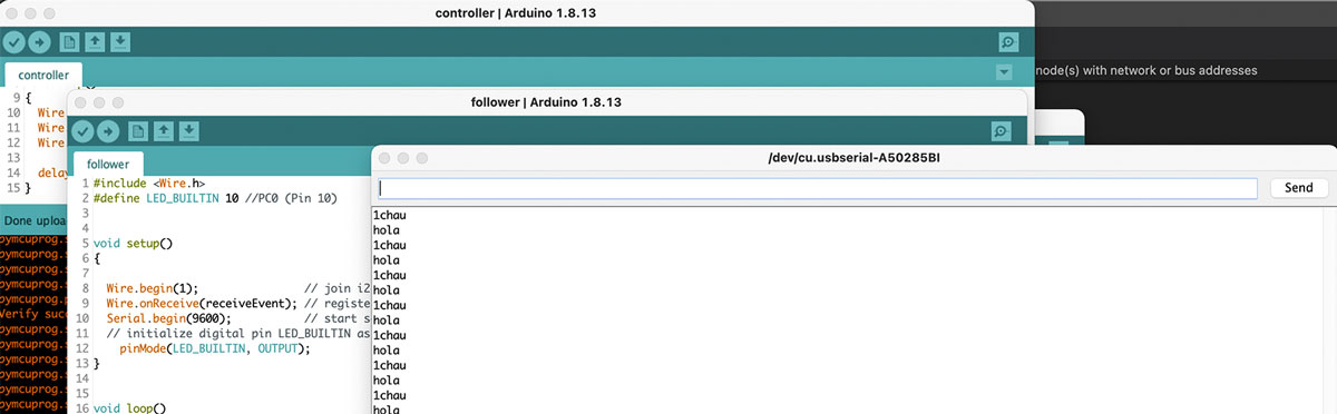
Then, I flashed the follower with this code:
#include <Wire.h>
#define LED_BUILTIN 10 //PC0 (Pin 10)


void setup()
{

  Wire.begin(1);                // join i2c bus with address #1
  Wire.onReceive(receiveEvent); // register event
  Serial.begin(9600);           // start serial for output
  // initialize digital pin LED_BUILTIN as an output.
    pinMode(LED_BUILTIN, OUTPUT);
}


void loop()
{
  delay(500);
  Serial.println("chau");

}

bool ledon = false; //boolean variable

// function that executes whenever data is received from master
// this function is registered as an event, see setup()
void receiveEvent(int howMany)
{
  Serial.println("hola");

    char c = Wire.read(); // receive byte as a character
    Serial.print(c);         // print the character

    if (ledon){
      digitalWrite(LED_BUILTIN, LOW);    // if the LED is on then turn the LED off by making the voltage LOW
    } else {
      digitalWrite(LED_BUILTIN, HIGH);   // if the LED is off turn the LED on (HIGH is the voltage level)
    }
   ledon = !ledon; // ledon is the variable that indicates if the LED is on or off

}
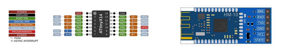
Connecting My Board and My Phone Using an HC-10
I had to check the pinout diagram to confirm the Tx and Rx pins for the ATtiny1614. The HC-10 module is quite simple for wiring, with connections for Tx, Rx, GND, and VCC. This module operates at 3.3V, so I chose it for its low energy consumption, which is crucial for keeping my device compact.
In discussing the final project with Oscar, he shared this repository.
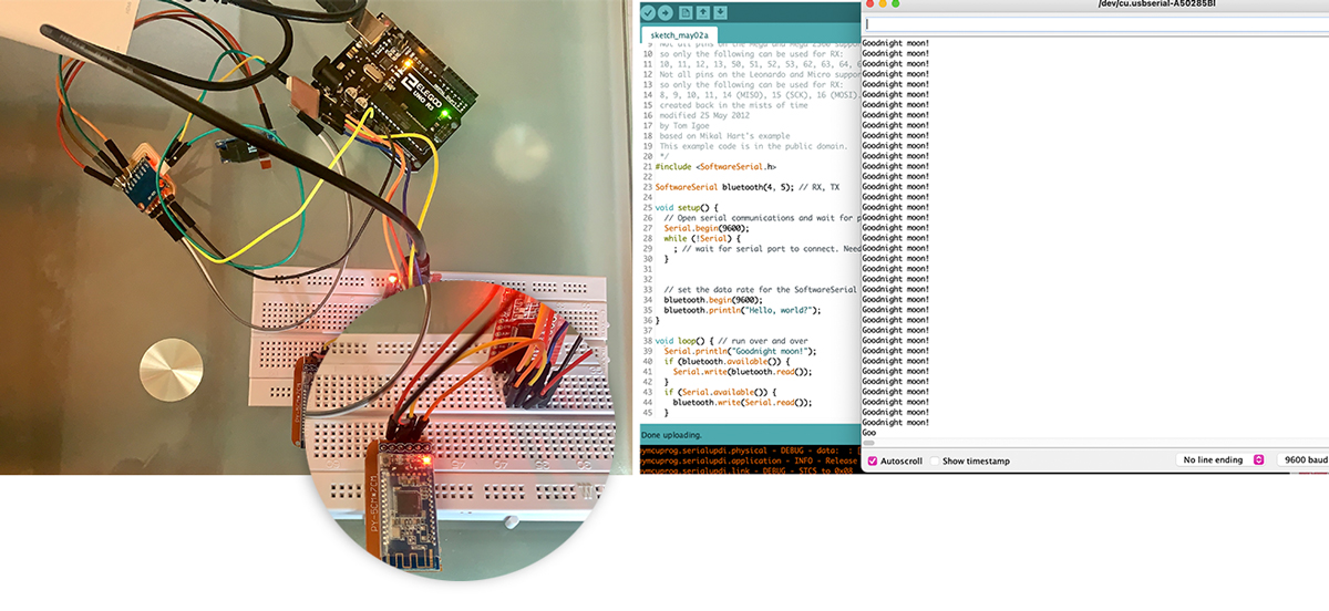
I started by flashing the code to see if it worked. In my setup, Tx was connected to pin 5 and Rx to pin 4. I also moved the “Goodnight moon!” message out of the setup to ensure constant validation.
/*
  Software serial multple serial test
 Receives from the hardware serial, sends to software serial.
 Receives from software serial, sends to hardware serial.
 The circuit:
 * RX is digital pin 10 (connect to TX of other device)
 * TX is digital pin 11 (connect to RX of other device)
 Note:
 Not all pins on the Mega and Mega 2560 support change interrupts,
 so only the following can be used for RX:
 10, 11, 12, 13, 50, 51, 52, 53, 62, 63, 64, 65, 66, 67, 68, 69
 Not all pins on the Leonardo and Micro support change interrupts,
 so only the following can be used for RX:
 8, 9, 10, 11, 14 (MISO), 15 (SCK), 16 (MOSI).
 created back in the mists of time
 modified 25 May 2012
 by Tom Igoe
 based on Mikal Hart's example
 This example code is in the public domain.
 */
#include <SoftwareSerial.h>

SoftwareSerial bluetooth(5, 4); // RX, TX

void setup() {
  // Open serial communications and wait for port to open:
  Serial.begin(9600);
  while (!Serial) {
    ; // wait for serial port to connect. Needed for native USB port only
  }

  Serial.println("Goodnight moon!");

  // set the data rate for the SoftwareSerial port
  bluetooth.begin(9600);
  bluetooth.println("Hello, world?");
}

void loop() { // run over and over
  if (bluetooth.available()) {
    Serial.write(bluetooth.read());
  }
  if (Serial.available()) {
    bluetooth.write(Serial.read());
  }
}
It worked fine.
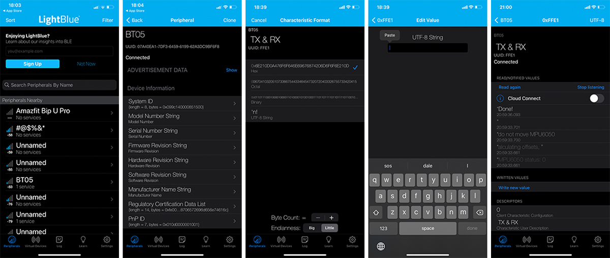
Next, I needed to share information with another device. I followed this tutorial and downloaded the app LightBlue from the Apple Store. LightBlue is an app that connects to devices using BLE (Bluetooth Low Energy), which the HC-10 supports. I also checked out How to use LightBlue to understand how to write and receive messages.
Trying LightBlue
- First, select the device. Mine was BT05, which I found by connecting and disconnecting.
- Scroll down and tap TX & RX. To view data on the screen, select UTF-8 string; HEX is selected by default.
- To send a message to the device, choose “Write new value.”
- To receive data from the device or send a message via the serial monitor, select “Listen.”
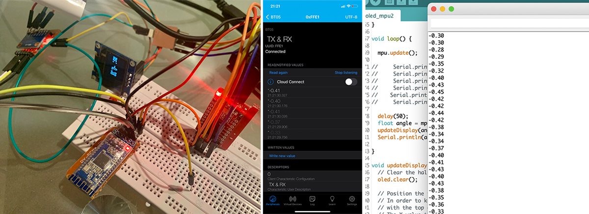
For my project, I wanted to display the gyroscope’s position on my phone. To achieve this, I needed to integrate my new code with the previous one that controlled the OLED and MPU6050. My goal was to send the angle Y to my phone and simultaneously display it on the OLED.
I used the following code:
// Choose your I2C implementation before including Tiny4kOLED.h
// The default is selected is Wire.h

// To use the Wire library:
//#include <Wire.h>

// To use the Adafruit's TinyWireM library:
//#include <TinyWireM.h>

// To use the TinyI2C library from https://github.com/technoblogy/tiny-i2c
//#include <TinyI2CMaster.h>


#include <Tiny4kOLED.h>
#include <Wire.h>
#include <MPU6050_light.h>
MPU6050 mpu(Wire);

#include <SoftwareSerial.h>

SoftwareSerial bluetooth(4, 5); // RX, TX


void setup() {
 // set the data rate for the SoftwareSerial port
  bluetooth.begin(9600);

  // Send the initialization sequence to the oled. This leaves the display turned off
  oled.begin();

  // Two rotations are supported,
  // The begin() method sets the rotation to 1.
  //oled.setRotation(0);

  // Some newer devices do not contain an external current reference.
  // Older devices may also support using the internal curret reference,
  // which provides more consistent brightness across devices.
  // The internal current reference can be configured as either low current, or high current.
  // Using true as the parameter value choses the high current internal current reference,
  // resulting in a brighter display, and a more effective contrast setting.
  //oled.setInternalIref(true);

  // Two fonts are supplied with this library, FONT8X16 and FONT6X8
  // Other fonts are available from the TinyOLED-Fonts library
  oled.setFont(FONT8X16);

  // Clear the memory before turning on the display
  oled.clear();

  // Turn on the display
  oled.on();

  // Switch the half of RAM that we are writing to, to be the half that is non currently displayed
  oled.switchRenderFrame();
  Serial.begin(9600);
   Wire.begin();
 byte status = mpu.begin();
   Serial.print(F("MPU6050 status: "));
   Serial.println(status);
   while (status != 0) { } // stop everything if could not connect to MPU6050
 Serial.println(F("Calculating offsets, do not move MPU6050"));
   delay(1000);
   mpu.calcOffsets(); // gyro and accelero
   Serial.println("Done!\n");
}

void loop() {

  mpu.update();

//     Serial.print("X : ");
//     Serial.print(mpu.getAngleX());
//     Serial.print("\tY : ");
//     Serial.print();
//    Serial.print("\tZ : ");
//     Serial.println(mpu.getAngleZ());

  delay(50);
  float angle = mpu.getAngleY(); // declare the angle Y of the gyro on the variable angle
  updateDisplay(angle);
  Serial.println(angle);

}

void updateDisplay(float angleY) {
  // Clear the half of memory not currently being displayed.
  oled.clear();

  // Position the text cursor
  // In order to keep the library size small, text can only be positioned
  // with the top of the font aligned with one of the four 8 bit high RAM pages.
  // The Y value therefore can only have the value 0, 1, 2, or 3.
  // usage: oled.setCursor(X IN PIXELS, Y IN ROWS OF 8 PIXELS STARTING WITH 0);
  oled.setCursor(0, 1);

  // Write text to oled RAM (which is not currently being displayed).
  oled.print(F("ms: "));

  // Write the number of milliseconds since power on.
  oled.print(mpu.getAngleY());

  // Swap which half of RAM is being written to, and which half is being displayed.
  // This is equivalent to calling both switchRenderFrame and switchDisplayFrame.
  oled.switchFrame();
}
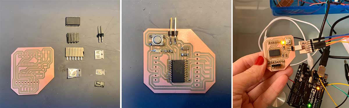
New board: Attiny3216
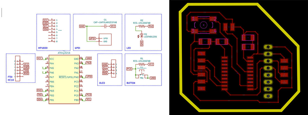
After struggling with Attiny1614 memory size I decided to make a new board using an Attiny3216. I’m iterating towards the board for my final project but I need to define a size as soon as possible. My device need to be small enough to fit on top of a shoe. So, I started thinking of sandwich and how my components should be placed. After some consideration, I ended up with this board.
Schematic of the new board. I missed connecting the LED to VCC so I made a switch between the LED and the resistor.
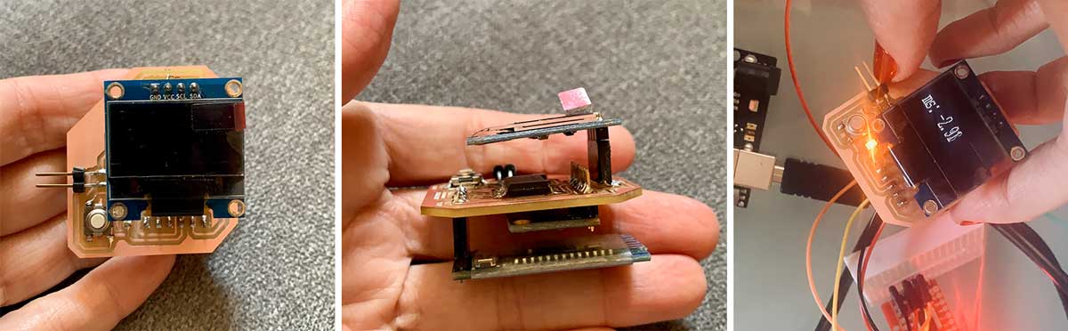
Soldering and testing my board.
Testing the board with the modules with the code that I used to flash the Attiny1614.
Download files here:
- Bluetooth + Gyro + OLED
- Bluetooth + Gyro + OLED
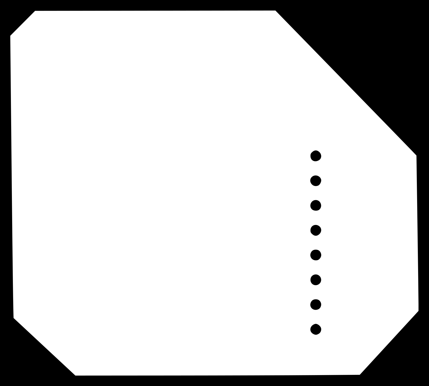
- New Attiny3216 svg
- New Attiny3216 interior
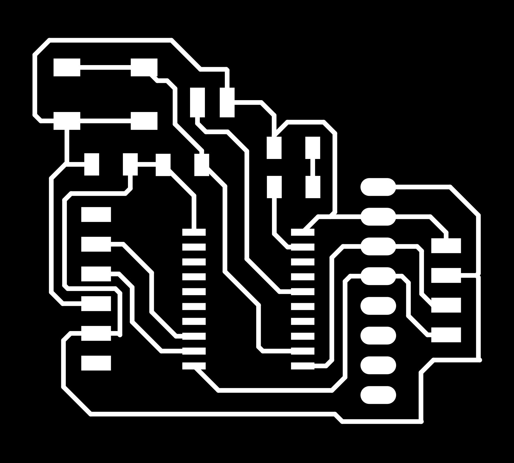
- New Attiny3216 traces
- New Attiny3216 interior_millling
- New Attiny3216 milling
- Kicad schematic
- Kicad PCB
My next steps are:
- Add the battery (3.3V) and the battery charger.
- Improve board design (fix LED, add holes, improve the use of height).
- Connect the board with Unity 3D.
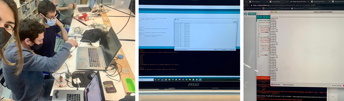
Sending a message between two projects
I worked on this with Diego, as we were both working with I2C and ATtinys. We decided to merge his test code with mine.
We ended up with this code for the controller:
#include <Wire.h>

void setup() {
  Wire.begin();        // join i2c bus (address optional for master)
  Serial.begin(9600);  // start serial for output
  Serial.println("start");
  delay(1000);
}

void loop() {
  Serial.println("first req");
  Wire.requestFrom(8, 6);    // request 6 bytes from slave device #8
  Serial.println("requesting");

  while (Wire.available()) { // slave may send less than requested
    Serial.println("reading");
    char c = Wire.read();    // receive a byte as character
    Serial.print(c);         // print the character
  }

  delay(500);
}
And for the follower, we ended up using Diego’s code. We found that our boards were not working well together. Josep helped us figure out what was going on, and then Edu discovered that a 10k resistor was needed to make the communication more stable.
#include <Wire.h>

void setup() {
      Wire.begin(8);                // join i2c bus with address #8
      Wire.onRequest(requestEvent); // register event
  }
void loop() {
      delay(100);
  }

  // function that executes whenever data is requested by master
  // this function is registered as an event, see setup()
void requestEvent() {
      Wire.write("diego "); // respond with message of 6 bytes
      // as expected by master
  }
Tip
Our takeaway from this part of the assignment was that I2C may need resistors for SDA and SCL to be more stable. In some boards, it can work perfectly, but in others, things like the OLED suddenly turning off or failures for no reason can occur. So, I decided to add a couple of resistors to my new-to-be-designed board.