Electronics Process
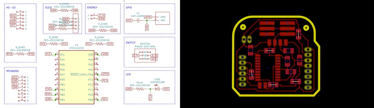
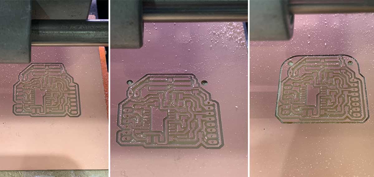
I designed the board using KiCad and then milled it on a copper-laminated board with the Roland SRM-20. This process followed the guidelines from the Electronics Design and Electronics Production weeks.
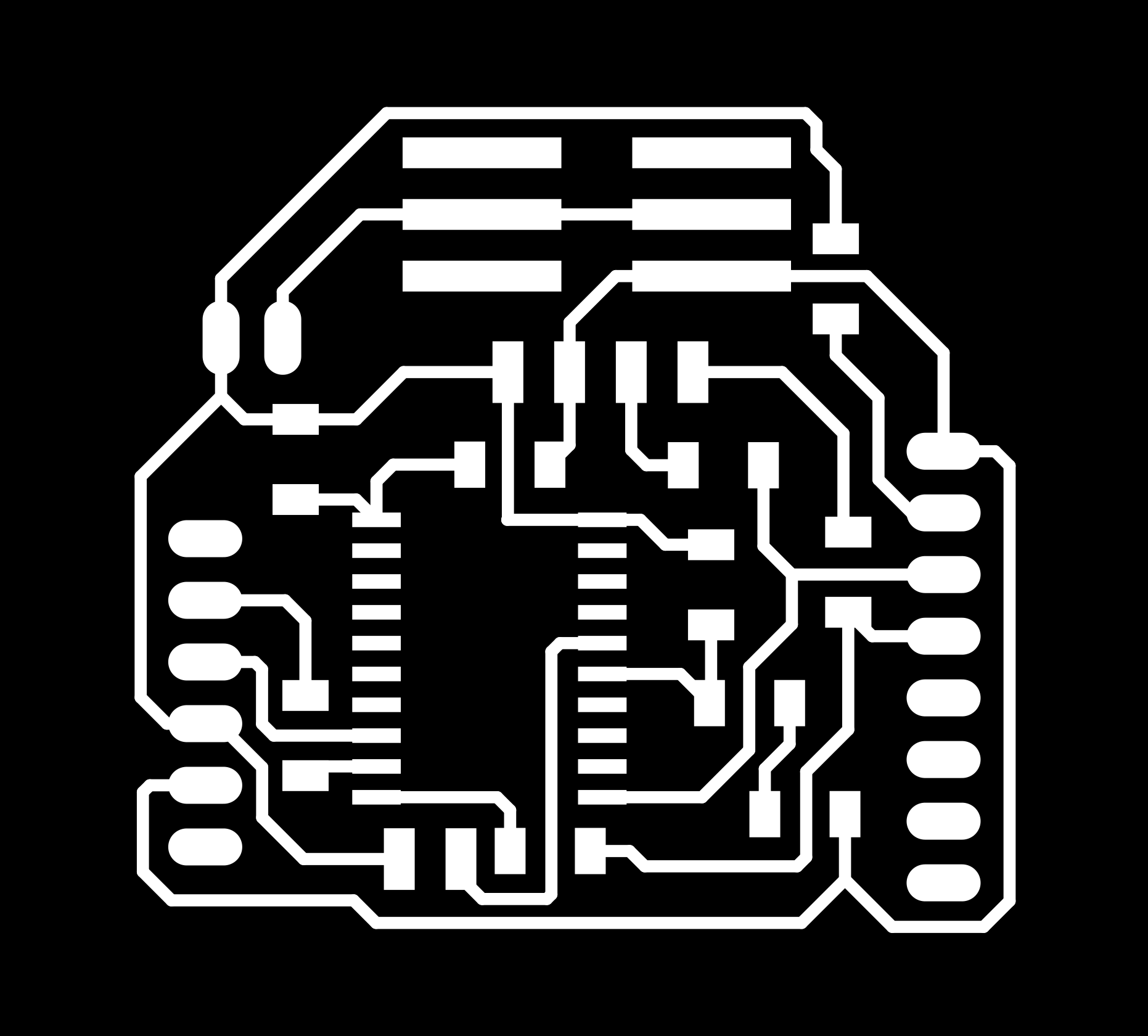
Design and Milling
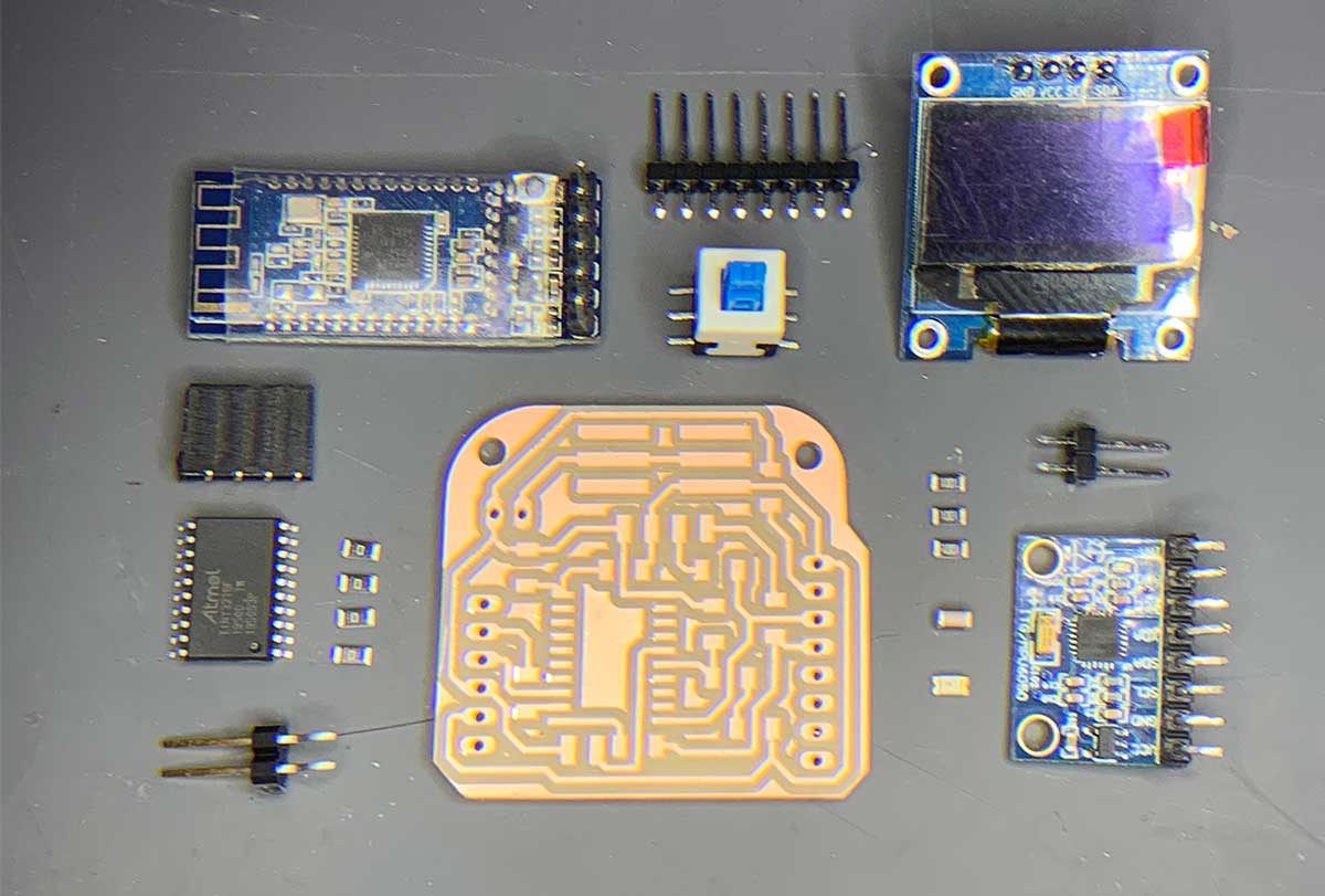
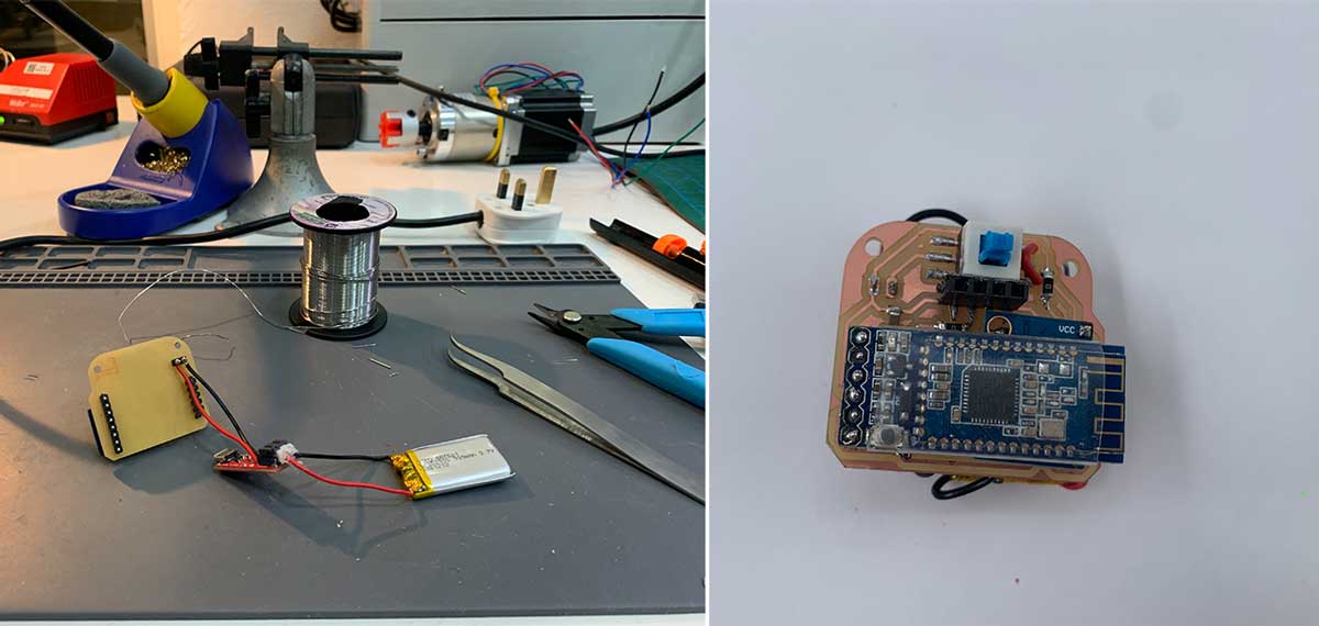
For the board, I used an ATtiny3216 and added various pin headers to accommodate the assembly of components. The OLED screen is detachable and secured in the housing with screws. I created three different files to manage the holes before milling the interior of the board.
Design Files and Components
- ATtiny3216: Microcontroller used for the board.
- Pin Headers: For component assembly.
- 0 Ohm Resistors: Made circuit design easier.
- Button Type Switch: For simple on/off functionality.
- 3.7V 300mAh Battery: Based on an approximate calculation of circuit requirements.
Final Files
You can find the final design files and associated resources here:
- Final Board SVG
- Final Board Holes PNG
- Final Board Holes RML
- Final Board Interior PNG
- Final Board Interior RML
- Final Board Traces PNG
- Final Board Traces RML
- KiCad Schematic Final Board
- KiCad PCB Final Board
Last update: September 16, 2024